Herunterladen Inhalt Inhalt Diese Seite drucken
Inhaltsverzeichnis

Werbung

Verfügbare Sprachen

Verfügbare Sprachen

All manuals and user guides at all-guides.com
Quick Start
Thank you for purchasing the MSI
B350M BAZOOKA/ A320M
®
BAZOOKA
motherboard. This Quick Start section provides
demonstration diagrams about how to install your computer. Some
of the installations also provide video demonstrations. Please link
to the URL to watch it with the web browser on your phone or tablet.
You may have even link to the URL by scanning the QR code.
Kurzanleitung
Danke, dass Sie das MSI
B350M BAZOOKA/ A320M BAZOOKA
®
Motherboard gewählt haben. Dieser Abschnitt der Kurzanleitung
bietet eine Demo zur Installation Ihres Computers. Manche
Installationen bieten auch die Videodemonstrationen. Klicken Sie
auf die URL, um diese Videoanleitung mit Ihrem Browser auf Ihrem
Handy oder Table anzusehen. Oder scannen Sie auch den QR Code
mit Ihrem Handy, um die URL zu öffnen.
Présentation rapide
Merci d' avoir choisi la carte mère MSI
B350M BAZOOKA/ A320M
®
BAZOOKA. Ce manuel fournit une rapide présentation avec des
illustrations explicatives qui vous aideront à assembler votre
ordinateur. Des tutoriels vidéo sont disponibles pour certaines
étapes. Cliquez sur le lien fourni pour regarder la vidéo sur votre
téléphone ou votre tablette. Vous pouvez également accéder au lien
en scannant le QR code qui lui est associé.
Быстрый старт
Благодарим вас за покупку материнской платы MSI
B350M
®
BAZOOKA. В этом разделе представлена
BAZOOKA/ A320M
информация, которая поможет вам при сборке комьютера.
Для некоторых этапов сборки имеются видеоинструкции.
Для просмотра видео, необходимо открыть
соответствующую ссылку в веб-браузере на вашем телефоне
или планшете. Вы также можете выполнить переход по
ссылке, путем сканирования QR-кода.
I
Quick Start

Werbung

Inhaltsverzeichnis
loading

Inhaltszusammenfassung für MSI B350M BAZOOKA

  • Seite 1 Handy oder Table anzusehen. Oder scannen Sie auch den QR Code mit Ihrem Handy, um die URL zu öffnen. Présentation rapide Merci d’ avoir choisi la carte mère MSI B350M BAZOOKA/ A320M ® BAZOOKA. Ce manuel fournit une rapide présentation avec des illustrations explicatives qui vous aideront à...
  • Seite 2 All manuals and user guides at all-guides.com Installing a Processor/ Installation des Prozessors/ Installer un processeur/ Установка процессора https://youtu.be/Xv89nhFk1vc Quick Start...
  • Seite 3 All manuals and user guides at all-guides.com Installing DDR4 memory/ Installation des DDR4-Speichers/ Installer une mémoire DDR4/ Установка памяти DDR4 http://youtu.be/T03aDrJPyQs DIMMB2 DIMMB2 DIMMB1 DIMMA2 DIMMA2 DIMMA2 DIMMA1 Quick Start...
  • Seite 4 All manuals and user guides at all-guides.com Connecting the Front Panel Header/ Anschließen der Frontpanel-Stiftleiste/ Connecter un connecteur du panneau avant/ Подключение разъемов передней панели http://youtu.be/DPELIdVNZUI HDD LED + Power LED + HDD LED - Power LED - Reset Switch Power Switch Reset Switch Power Switch...
  • Seite 5 All manuals and user guides at all-guides.com Installing the Motherboard/ Installation des Motherboards/ Installer la carte mère/ Установка материнской платы Quick Start...
  • Seite 6 All manuals and user guides at all-guides.com Installing SATA Drives/ Installation der SATA-Laufwerke/ Installer le disque dur SATA/ Установка дисков SATA http://youtu.be/RZsMpqxythc Quick Start...
  • Seite 7 All manuals and user guides at all-guides.com Installing a Graphics Card/ Einbau der Grafikkarte/ Installer une carte graphique/ Установка дискретной видеокарты http://youtu.be/mG0GZpr9w_A Quick Start...
  • Seite 8 All manuals and user guides at all-guides.com Connecting Peripheral Devices/ Peripheriegeräte/ Connecter un périphérique anschliessen/ Подключение периферийных устройств VIII Quick Start...
  • Seite 9 All manuals and user guides at all-guides.com Connecting the Power Connectors/ Stromanschlüsse anschliessen/ Connecter les câbles du module d’ alimentation/ Подключение разъемов питания http://youtu.be/gkDYyR_83I4 ATX_PWR1 CPU_PWR1 Quick Start...
  • Seite 10: Power On/ Einschalten/ Mettre Sous-Tension/ Включение Питания

    All manuals and user guides at all-guides.com Power On/ Einschalten/ Mettre sous-tension/ Включение питания Quick Start...
  • Seite 11: Inhaltsverzeichnis

    All manuals and user guides at all-guides.com Contents Safety Information ....................2 Specifications ......................3 Rear I/O Panel ....................... 7 LAN Port LED Status Table..................7 Realtek HD Audio Manager ..................7 Overview of Components ..................9 CPU Socket ......................10 DIMM Slots ......................
  • Seite 12: Safety Information

    All manuals and user guides at all-guides.com Safety Information The components included in this package are prone to damage from electrostatic discharge (ESD). Please adhere to the following instructions to ensure successful computer assembly. Ensure that all components are securely connected. Loose connections may cause the computer to not recognize a component or fail to start.
  • Seite 13: Specifications

    Support ECC UDIMM memory (non-ECC mode) Support non-ECC UDIMM memory * 7th Gen A-series/ Athlon processors support a maximum of DDR4 2400 Mhz. Please refer www.msi.com for more information on compatible memory. 1x PCIe 3.0 x16 slot RYZEN series processors support x16 mode ƒ...
  • Seite 14 4x USB 3.1 Gen1 (SuperSpeed USB) Type-A ports on the ƒ back panel 1x PS/2 keyboard/ mouse combo port 4x USB 2.0 Type-A ports (B350M BAZOOKA) 2x USB 2.0 Type-A ports (A320M BAZOOKA) 1x VGA port Back Panel 1x DVI-D port Connectors 1x HDMI™...
  • Seite 15 All manuals and user guides at all-guides.com Continued from previous page 1x 24-pin ATX main power connector 1x 8-pin ATX 12V power connector 4x SATA 6Gb/s connectors 2x USB 2.0 connectors (supports additional 4 USB 2.0 ports) 1x USB 3.1 Gen1 connector (supports additional 2 USB 3.1 Gen1 ports) 1x 4-pin CPU fan connector 2x 4-pin system fan connectors...
  • Seite 16 All manuals and user guides at all-guides.com Continued from previous page Drivers SUPER CHARGER COMMAND CENTER LIVE UPDATE 6 MSI SMART TOOL DRAGON EYE GAMING APP Software X-BOOST RAMDISK GAMING LAN MANAGER SteelSeries Engine 3 CPU-Z MSI GAMING Google Chrome ,Google Toolbar, Google Drive ™...
  • Seite 17: Rear I/O Panel

    All manuals and user guides at all-guides.com Rear I/O Panel (only for B350M BAZOOKA) Line-in USB 2.0 PS/2 USB 3.1 Gen1 Line-out Mic-in USB 2.0 DVI-D USB 3.1 Gen1 LAN Port LED Status Table Link/ Activity LED Speed LED Status...
  • Seite 18 All manuals and user guides at all-guides.com Device Selection - allows you to select a audio output source to change the related options. The check sign indicates the devices as default. Application Enhancement - the array of options will provide you a complete guidance of anticipated sound effect for both output and input device.
  • Seite 19: Overview Of Components

    All manuals and user guides at all-guides.com Overview of Components SYS_FAN1 DIMMA1 DIMMA2 CPU_FAN1 DIMMB1 DIMMB2 CPU Socket CPU_PWR1 ATX_PWR1 SATA1 SATA2 PCI_E1 M2_1 SATA▼3▲4 PCI_E2 PCI_E3 JCI1 JBAT1 JFP2 JFP1 JAUD1 JUSB3 JUSB2 SYS_FAN2 JUSB1 JLED1 JLPT1 JCOM1 JTPM1 Overview of Components...
  • Seite 20: Cpu Socket

    This motherboard is designed to support overclocking. Before attempting to overclock, please make sure that all other system components can tolerate overclocking. Any attempt to operate beyond product specifications is not recommended. MSI does not guarantee the damages or risks caused by ®...
  • Seite 21: Dimm Slots

    Due to AM4 CPU/memory controller official specification limitation, the frequency of memory modules may operate lower than the marked value under the default state. Please refer www.msi.com for more information on compatible memory. Overview of Components...
  • Seite 22: Pci_E1~3: Pcie Expansion Slots

    PCI_E2: PCIe 2.0 x1 PCI_E3: PCIe 2.0 x1 Important If you install a large and heavy graphics card, you need to use a tool such as MSI Gaming Series Graphics Card Bolster to support its weight to prevent deformation of the slot.
  • Seite 23: M2_1: M.2 Slot (Key M)

    All manuals and user guides at all-guides.com M2_1: M.2 Slot (Key M) Video Demonstration Watch the video to learn how to Install M.2 module. http://youtu.be/JCTFABytrYA Installing M.2 module Remove the screw from the base screw. Remove the base screw. Tighten the base screw into the hole of the distance to the M.2 slot as the length your M.2...
  • Seite 24: Jaud1: Front Audio Connector

    All manuals and user guides at all-guides.com JAUD1: Front Audio Connector This connector allows you to connect audio jacks on the front panel. MIC L Ground MIC R Head Phone R MIC Detection SENSE_SEND No Pin Head Phone L Head Phone Detection JFP1, JFP2: Front Panel Connectors These connectors connect to the switches and LEDs on the front panel.
  • Seite 25: Cpu_Pwr1, Atx_Pwr1: Power Connectors

    All manuals and user guides at all-guides.com CPU_PWR1, ATX_PWR1: Power Connectors These connectors allow you to connect an ATX power supply. CPU_PWR1 Ground +12V Ground +12V Ground +12V Ground +12V +3.3V +3.3V +3.3V -12V Ground Ground PS-ON# Ground Ground Ground ATX_PWR1 Ground Ground...
  • Seite 26: Jusb1~2: Usb 2.0 Connectors

    All manuals and user guides at all-guides.com JUSB1~2: USB 2.0 Connectors These connectors allow you to connect USB 2.0 ports on the front panel. USB0- USB1- USB0+ USB1+ Ground Ground No Pin Important Note that the VCC and Ground pins must be connected correctly to avoid possible damage.
  • Seite 27: Cpu_Fan1, Sys_Fan1~2: Fan Connectors

    All manuals and user guides at all-guides.com CPU_FAN1, SYS_FAN1~2: Fan Connectors Fan connectors can be classified as PWM (Pulse Width Modulation) Mode or DC Mode. PWM Mode fan connectors provide constant 12V output and adjust fan speed with speed control signal. DC Mode fan connectors control fan speed by changing voltage. When you plug a 3-pin (Non-PWM) fan to a fan connector in PWM mode, the fan speed will always maintain at 100%, which might create a lot of noise.
  • Seite 28: Jci1: Chassis Intrusion Connector

    All manuals and user guides at all-guides.com JCI1: Chassis Intrusion Connector This connector allows you to connect the chassis intrusion switch cable. Normal Trigger the chassis intrusion event (default) Using chassis intrusion detector Connect the JCI1 connector to the chassis intrusion switch/ sensor on the chassis. Close the chassis cover.
  • Seite 29: Jled1: Rgb Led Strip Connector

    All manuals and user guides at all-guides.com JLED1: RGB LED strip connector This connector allows you to connect the extended 5050 RGB LED strips. +12V 5050 LED strip JLED1 Video Demonstration Watch the video to learn how to install 5050 RGB LED strips to RGB LED connector.
  • Seite 30: Jbat1: Clear Cmos (Reset Bios) Jumper

    All manuals and user guides at all-guides.com JBAT1: Clear CMOS (Reset BIOS) Jumper There is CMOS memory onboard that is external powered from a battery located on the motherboard to save system configuration data. If you want to clear the system configuration, set the jumpers to clear the CMOS memory.
  • Seite 31: Bios Setup

    All manuals and user guides at all-guides.com BIOS Setup The default settings offer the optimal performance for system stability in normal conditions. You should always keep the default settings to avoid possible system damage or failure booting unless you are familiar with BIOS. Important BIOS items are continuously update for better system performance.
  • Seite 32: Resetting Bios

    Updating BIOS Updating BIOS with M-FLASH Before updating: Please download the latest BIOS file that matches your motherboard model from MSI website. And then save the BIOS file into the USB flash drive. Updating BIOS: Press Del key to enter the BIOS Setup during POST.
  • Seite 33: Ez Mode

    All manuals and user guides at all-guides.com EZ Mode At EZ mode, it provides the basic system information and allows you to configure the basic setting. To configure the advanced BIOS settings, please enter the Advanced Mode by pressing the Setup Mode switch or F7 function key. Screenshot A-XMP switch Setup Mode switch...
  • Seite 34 All manuals and user guides at all-guides.com Information display - click on the CPU, Memory, Storage, Fan Info and Help buttons on left side to display related information. Function buttons - enable or disable the LAN Option ROM, HD audio controller, AHCI, RAID, CPU Fan Fail Warning Control and BIOS Log Review by clicking on their respective button.
  • Seite 35: Advanced Mode

    All manuals and user guides at all-guides.com Advanced Mode Press Setup Mode switch or F7 function key can switch between EZ Mode and Advanced Mode in BIOS setup. Screenshot A-XMP switch Setup Mode switch Search Language System information GAME BOOST switch Boot device priority bar...
  • Seite 36: Oc Menu

    All manuals and user guides at all-guides.com OC Menu This menu is for advanced users who want to overclock the motherboard. Important Overclocking your PC manually is only recommended for advanced users. Overclocking is not guaranteed, and if done improperly, it could void your warranty or severely damage your hardware.
  • Seite 37 All manuals and user guides at all-guides.com Advanced DRAM Configuration Press Enter to enter the sub-menu. User can set the memory timing for each/ all memory channel. The system may become unstable or unbootable after changing memory timing. If it occurs, please clear the CMOS data and restore the default settings.
  • Seite 38 All manuals and user guides at all-guides.com CPU Memory Changed Detect [Enabled]* Enables or disables the system to issue a warning message during boot when the CPU or memory has been replaced. [Enabled] The system will issue a warning message during boot and then you have to load the default settings for new devices.
  • Seite 39: Software Description

    7/ 10 disc into your optical drive. ® Note: Due to chipset limitation, during the Windows 7 installation process, USB optical drives or USB flash drives are not supported. You can use MSI Smart Tool to install Windows ® Press the Restart button on the computer case.
  • Seite 40: Installing Utilities

    All manuals and user guides at all-guides.com Installing Utilities Before you install utilities, you must complete drivers installation. Insert MSI Driver Disc into your optical drive. ® The installer will automatically appear. Click Utilities tab. Select the utilities you want to install.
  • Seite 41 All manuals and user guides at all-guides.com Inhalt Sicherheitshinweis ....................2 Spezifikationen ...................... 3 Rückseite E/A ......................7 LAN Port LED Zustandstabelle ................7 Realtek HD Audio Manager ..................7 Übersicht der Komponenten ................. 9 CPU Sockel ......................10 DIMM Steckplätze ....................11 PCI_E1~3: PCIe Erweiterungssteckplätze ............
  • Seite 42: Sicherheitshinweis

    All manuals and user guides at all-guides.com Sicherheitshinweis Die im Paket enthaltene Komponenten sind der Beschädigung durch elektrostatischen Entladung (ESD). Beachten Sie bitte die folgenden Hinweise, um die erfolgreichen Computermontage sicherzustellen. Stellen Sie sicher, dass alle Komponenten fest angeschlossen sind. Lockere Steckverbindungen können Probleme verursachen, zum Beispiel: Der Computer erkennt eine Komponente nicht oder startet nicht.
  • Seite 43: Spezifikationen

    Chipsatz A320 Chipsatz (A320M BAZOOKA) ® 4x DDR4 Speicherplätze, aufrüstbar bis 64GB Unterstützen DDR4 1866/ 2133/ 2400/ 2667(OC)/ ƒ 2933(OC)/ 3200(OC)+ Mhz* (B350M BAZOOKA) Unterstützen DDR4 1866/ 2133/ 2400/ 2667(OC) Mhz* ƒ (A320M BAZOOKA) Speicher Dual-Kanal-Speicherarchitektur Unterstützen ECC UDIMM-Speicher (non-ECC Modus) Unterstützen non-ECC UDIMM-Speicher...
  • Seite 44 4x USB 3.1 Gen1 (SuperSpeed USB) Typ-A Anschlüsse an ƒ der rückseitigen Anschlussleiste PS/2 Tastatur/ Maus-Combo-Anschluss x1 USB 2.0 Typ-A Anschlüsse x4 (B350M BAZOOKA) USB 2.0 Typ-A Anschlüsse x2 (A320M BAZOOKA) VGA Anschluss x1 Hintere Ein-/ und DVI-D Anschluss x1 Ausgänge...
  • Seite 45 All manuals and user guides at all-guides.com Fortsetzung der vorherigen Seite 24-poliger ATX Stromanschluss x1 8-poliger ATX12V Stromanschluss x1 SATA 6Gb/s Anschlüsse x4 USB 2.0 Anschlüsse x2 (unterstützt zusätzliche 4 USB 2.0 Anschlüsse) USB 3.1 Gen1 Anschluss x1 (unterstützt zusätzliche 2 USB 3.1 Gen1 Anschlüsse) 4-poliger CPU-Lüfter-Anschluss x1 4-polige System-Lüfter-Anschlüsse x2...
  • Seite 46 VR Ready GAMING HOTKEY GAMING MAUS Steuerung Click BIOS 5 AMD FreeSync Ready ™ AMD OverDriver Ready ™ GAMING Certified SteelSeries Certified WTFast* * Dieses Angebot steht nur für begrenzte Zeit zur Verfügung, weitere Informationen finden Sie unter www.msi.com Spezifikationen...
  • Seite 47: Rückseite E/A

    All manuals and user guides at all-guides.com Rückseite E/A (Nur für B350M BAZOOKA) Line-In USB 2.0 PS/2 USB 3.1 Gen1 Line-Out Mic-In USB 2.0 DVI-D USB 3.1 Gen1 LAN Port LED Zustandstabelle Verbindung/ Aktivität LED Geschwindigkeit LED Zustand Bezeichnung Zustand...
  • Seite 48 All manuals and user guides at all-guides.com Geräteauswahl - Ermöglicht die Auswahl der Audio-Ausgangs Quelle. Das aktuell aktivierte Gerät ist mit einem Haken gekennzeichnet. Optimierungen - Die Vielfalt an Optionen bietet eine komplette Anleitung von erwarteten Sound-Effekt für beide Ausgangs- und Eingangsvorrichtung. Lautstärke - Steuert die Lautstärke und die Balance-Einstellung der Lautsprecher, die im Front-Panel oder auf der Rückseite des PCs eingesteckt sind.
  • Seite 49: Übersicht Der Komponenten

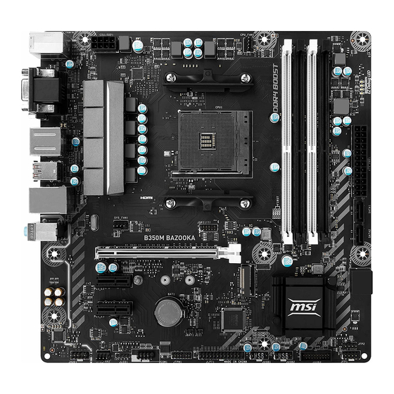
    All manuals and user guides at all-guides.com Übersicht der Komponenten SYS_FAN1 DIMMA1 DIMMA2 CPU_FAN1 DIMMB1 DIMMB2 CPU Sockel CPU_PWR1 ATX_PWR1 SATA1 SATA2 PCI_E1 M2_1 SATA▼3▲4 PCI_E2 PCI_E3 JCI1 JBAT1 JFP2 JFP1 JAUD1 JUSB3 JUSB2 SYS_FAN2 JUSB1 JLED1 JLPT1 JCOM1 JTPM1 Übersicht der Komponenten...
  • Seite 50: Cpu Sockel

    Sie jedoch bitte sicher, dass die betroffenen Komponenten mit den abweichenden Einstellungen während des Übertaktens zurecht kommen. Von jedem Versuch des Betriebes außerhalb der Produktspezifikationen kann nur abgeraten werden. MSI übernehmt keinerlei Garantie für die Schäden und Risiken, die aus einem unzulässigem Betrieb oder einem Betrieb außerhalb der Produktspezifikation resultieren.
  • Seite 51: Dimm Steckplätze

    CPU und den installierten Geräten. Speichermodule können auf Basis der offizielle Spezifikation der AM4 CPU/ des Speicher-Controllers mit einer niedrigeren Frequenz unter dem Standardzustand arbeiten. Weitere Informationen zu kompatiblen Speichermodulen finden Sie unter: http://www.msi.com. Übersicht der Komponenten...
  • Seite 52: Pci_E1~3: Pcie Erweiterungssteckplätze

    All manuals and user guides at all-guides.com PCI_E1~3: PCIe Erweiterungssteckplätze PCI_E1: PCIe 3.0 x16 (RYZEN Serie Prozessoren) PCIe 3.0 x8 (A-Serie/ Athlon der 7. Genera- ™ tion Prozessoren) PCI_E2: PCIe 2.0 x1 PCI_E3: PCIe 2.0 x1 Wichtig Wenn Sie eine große und schwere Grafikkarte einbauen, benötigen Sie einen Grafikkarten-Stabilisator (Graphics Card Bolster) der das Gewicht trägt und eine Verformung des Steckplatzes vermeidet.
  • Seite 53: M2_1: M.2 Steckplatz (Key M)

    All manuals and user guides at all-guides.com M2_1: M.2 Steckplatz (Key M) Video-Demonstration Eine anschauliche Darstellung zur Installation eines M.2 Moduls finden Sie im Video. http://youtu.be/JCTFABytrYA Installation eines M.2 Moduls Entfernen Sie die Schraube aus dem Schraubsockel. Entfernen Sie den Schraubsockel.
  • Seite 54: Jaud1: Audioanschluss Des Frontpanels

    All manuals and user guides at all-guides.com JAUD1: Audioanschluss des Frontpanels Dieser Anschluss ermöglicht den Anschluss von Audiobuchsen eines Frontpanels. MIC L Ground MIC R Head Phone R MIC Detection SENSE_SEND No Pin Head Phone L Head Phone Detection JFP1, JFP2: Frontpanel-Anschlüsse Diese Anschlüsse verbinden die Schalter und LEDs des Frontpanels.
  • Seite 55: Cpu_Pwr1, Atx_Pwr1: Stromanschlüsse

    All manuals and user guides at all-guides.com CPU_PWR1, ATX_PWR1: Stromanschlüsse Mit diesen Anschlüssen verbinden Sie die ATX Stromstecker. CPU_PWR1 Ground +12V Ground +12V Ground +12V Ground +12V +3.3V +3.3V +3.3V -12V Ground Ground PS-ON# Ground Ground Ground ATX_PWR1 Ground Ground PWR OK 5VSB +12V...
  • Seite 56: Jusb1~2: Usb 2.0 Anschlüsse

    Bitte beachten Sie, dass Sie die mit VCC (Stromführende Leitung) und Ground (Erdleitung) bezeichneten Pins korrekt verbinden müssen, ansonsten kann es zu Schäden kommen. Um das iPad, iPhone und den iPod über USB-Anschlüsse aufzuladen, installieren Sie bitte die MSI SUPER CHARGER Software.. ® JUSB3: USB 3.1 Gen1 Anschluss Mit diesem Anschluss können Sie den USB 3.1 Gen1 Anschluss auf dem Frontpanel...
  • Seite 57: Cpu_Fan1, Sys_Fan1~2: Stromanschlüsse Für Lüfter

    All manuals and user guides at all-guides.com CPU_FAN1, SYS_FAN1~2: Stromanschlüsse für Lüfter Diese Anschlüsse können im PWM (Pulse Width Modulation) Modus oder DC-Modus betrieben werden. Im PWM-Modus bieten die Lüfteranschlüsse konstante 12V Ausgang und regeln die Lüftergeschwindigkeit per Drehzahlsteuersignal. Im DC- Modus bestimmen die Lüfteranschlüsse die Lüftergeschwindigkeit durch Ändern der Spannung.
  • Seite 58: Jci1: Gehäusekontaktanschluss

    All manuals and user guides at all-guides.com JCI1: Gehäusekontaktanschluss Dieser Anschluss wird mit einem Kontaktschalter verbunden. Normal Löse den Gehäuseeingriff aus (Standardwert) Gehäusekontakt-Detektor verwenden Schließen Sie den JCI1-Anschluss am Gehäusekontakt-Schalter/ Sensor am Gehäuse an. Schließen Sie die Gehäuseabdeckung. Gehen Sie zu BIOS > SETTING > Security > Chassis Intrusion Configuration. Stellen Sie Chassis Intrusion auf Enabled.
  • Seite 59: Jled1: Rgb Led-Streifen Anschluss

    All manuals and user guides at all-guides.com JLED1: RGB LED-Streifen Anschluss Mit diesem Anschluss können Sie den 5050 RGB-LED-Streifen anschließen. +12V 5050 LED Streifen JLED1 Video-Demonstration In diesem Video erfahren Sie, wie Sie die 5050 RGB LED Streifen am RGB-LED-Anschluss anschließen können. https://youtu.be/CqNHyADzd2Q Wichtig Dieser Anschluss unterstützt die 5050 RGB Mehr-Farb-LED-Streifen (12V/R/G/B)
  • Seite 60: Jbat1: Clear Cmos Steckbrücke (Reset Des Bios)

    All manuals and user guides at all-guides.com JBAT1: Clear CMOS Steckbrücke (Reset des BIOS) Der Onboard CMOS Speicher (RAM) wird durch eine externe Spannungsversorgung durch eine Batterie auf dem Motherboard versorgt, um die Daten der Systemkonfiguration zu speichern. Wenn Sie die Systemkonfiguration löschen wollen, müssen Sie die Steckbrücke für kurze Zeit umsetzen.
  • Seite 61: Bios-Setup

    All manuals and user guides at all-guides.com BIOS-Setup Die Standardeinstellungen bieten die optimale Leistung für die Systemstabilität unter Normalbedingungen. Sie sollten immer die Standardeinstellungen behalten, um mögliche Schäden des Systems oder Boot-Fehler zu vermeiden, außer Sie besitzen ausreichende BIOS Kenntnisse. Wichtig BIOS Funktionen werden für eine bessere Systemleistung kontinuierlich aktualisiert.
  • Seite 62: Reset Des Bios

    Aktualisierung des BIOS mit dem M-FLASH-Programm Vorbereitung: Laden Sie bitte die neueste BIOS Version, die dem Motherboard-Modell entspricht, von der offiziellen MSI Website herunter und speichern Sie die BIOS-Datei auf USB-Flash- Laufwerk. BIOS-Aktualisierungsschritte: Drücken Sie während des POST-Vorgangs die Taste (Entf), um das BIOS zu öffnen.
  • Seite 63: Ez Modus

    All manuals and user guides at all-guides.com EZ Modus Im EZ-Modus können Sie die Grundinformationen des Systems einsehen und grundlegende Einstellungen konfigurieren. Um sich die erweiterten BIOS- Einstellungen anzeigen zu lassen, aktivieren Sie bitte den Erweiterten Modus durch Drücken des Setup Modus Schalter oder der Funktionstaste F7. Screenshot A-XMP Schalter Setup Modus Schalter...
  • Seite 64 All manuals and user guides at all-guides.com Systeminformationen - Diese zeigt CPU/ DDR-Frequenz, CPU/ MB-Temperatur, MB/ CPU-Typ, Speicherkapazität, CPU/ DDR-Spannung, BIOS-Version und Erstellungs-Datum. Boot-Geräte Prioritätsleiste - Sie können die Gerätesymbole verschieben, um die Startreihenfolge zu ändern. Die Bootreihenfolge sind mit “hoch” (links) bis “niedrig” (rechts) bezeichnet.
  • Seite 65: Erweiterter Modus

    All manuals and user guides at all-guides.com Erweiterter Modus Drücken Sie den Setup Modus Schalter oder die Funkionstaste F7, um zwischen dem EZ-Modus und Erweiterten-Modus im BIOS-Setup zu wechseln. Screenshot A-XMP Schalter Setup Modus Schalter Suchen Sprache System- information GAME BOOST Schalter Bootgeräte- Prioritätsleiste...
  • Seite 66: Oc Menü

    All manuals and user guides at all-guides.com OC Menü In diesem Menü können Benutzer das BIOS anpassen und das Mainboard übertakten. Bitte führen Sie nur Änderungen durch, wenn Sie sich über das Ergebnis im Klaren sind. Sie sollten Erfahrung beim Übertakten haben, da Sie sonst das Motherboard oder Komponenten des Systems beschädigen können.
  • Seite 67 All manuals and user guides at all-guides.com Adjusted DRAM Frequency Zeigt die Speicherfrequenz an. Nur Anzeige – keine Änderung möglich. Advanced DRAM Configuration Drücken Sie die Eingabetaste <Enter>, um das Untermenü aufzurufen. Der Anwender kann die Speicher-Timing für jeden Kanal des Speichers einstellen. Das System könnte nach dem Ändern der Speicher-Timings instabil werden oder nicht mehr booten.
  • Seite 68 All manuals and user guides at all-guides.com passen Sie deshalb den Strom sorgfältig an, um Beschädigungen des CPU/ VR MOS zu vermeiden. Wenn die Einstellung auf [Auto] gesetzt ist, wird das BIOS diese Einstellungen automatisch konfigurieren. CPU Voltages control [Auto] Erlaubt das Einstellen der CPU-Spannungen.
  • Seite 69: Softwarebeschreibung

    All manuals and user guides at all-guides.com Softwarebeschreibung Laden Sie die neuesten Treiber und Dienstprogramme von www.msi.com herunter und aktualisieren Sie sie. Installation von Windows 7 64-Bit/ Windows 10 64-Bit ® ® Schalten Sie den Computer ein. Legen Sie die Windows 7/ 10 Disk in das optisches Laufwerk.
  • Seite 70: Installation Von Utilities

    All manuals and user guides at all-guides.com Installation von Utilities Bevor Sie Anwendungen installieren, müssen Sie die Treiber-Installation vollständig beendet haben. Legen Sie die MSI Treiber Disk in das optisches Laufwerk. ® Der Installer wird automatisch erscheint. Klicken Sie auf Utilities.
  • Seite 71 All manuals and user guides at all-guides.com Table des matières Informations de sécurité ..................2 Spécifications ......................3 Panneau arrière Entrée/ Sortie ................7 Tableau explicatif de l’ état de la LED du port LAN ..........7 Realtek HD Audio Manager ..................7 Vue d’...
  • Seite 72: Informations De Sécurité

    All manuals and user guides at all-guides.com Informations de sécurité Les composants dans l’ emballage peuvent être endommagés par des décharges électrostatiques (ESD). Pour vous assurer de correctement monter votre ordinateur, veuillez vous référer aux instructions ci-dessous. Assurez-vous de bien connecter tous les composants. En cas de mauvaise connexion, il se peut que l’...
  • Seite 73: Spécifications

    * Les processeurs de série A ou Athlon ™ de 7ème génération supportent au maximum un taux de transfert de DDR4 2400 Mhz.Veuillez vous référer au site www.msi.com pour plus d’ informations sur la mémoire compatible. 1 x slot PCIe 3.0 x16 Les processeurs des séries RYZEN supportent mode x16...
  • Seite 74 4 x ports USB 3.1 Gen1 SuperSpeed USB Type-A sur le ƒ panneau arrière 1 x port clavier/ souris PS/2 4 x ports USB 2.0 Type-A (B350M BAZOOKA) 2 x ports USB 2.0 Type-A (A320M BAZOOKA) 1 x port VGA Connecteurs sur le 1 x port DVI-D panneau arrière...
  • Seite 75 All manuals and user guides at all-guides.com Suite du tableau de la page précédente 1 x connecteur d’ alimentation principal ATX 24 broches 1 x connecteur d’ alimentation ATX 12V 8 broches 4 x connecteurs SATA 6 Gb/s 2 x connecteurs USB 2.0 (support de 4 autres ports USB 2.0) 1 x connecteur USB 3.1 Gen1 (support de 2 autres ports USB 3.1 Gen1)
  • Seite 76 Contrôle de la souris GAMING Click BIOS 5 AMD FreeSync™ Ready AMD OverDriver™ Ready GAMING Certifié SteelSeries Certifié WTFast* * Cette fonctionnalité dépend d’ une offre limitée dans le temps. Veuillez vous référer au site www.msi.com pour plus d’ informations. Spécifications...
  • Seite 77: Panneau Arrière Entrée/ Sortie

    All manuals and user guides at all-guides.com Panneau arrière Entrée/ Sortie (seulement pour B350M BAZOOKA) Ligne-entrée USB 2.0 PS/2 USB 3.1 Gen1 Ligne- sortie Microphone USB 2.0 DVI-D entrée USB 3.1 Gen1 Tableau explicatif de l’ état de la LED du port LAN...
  • Seite 78 All manuals and user guides at all-guides.com Sélection du périphérique - vous permet de sélectionner une source de sortie audio pour en modifier les paramètres. Le symbole de coche indique le périphérique sélectionné par défaut. Amélioration d’ application - les diverses options vous fournissent un guide complet des effets acoustiques proposés pour les périphériques de sortie et d’...
  • Seite 79: Vue D' Ensemble Des Composants

    All manuals and user guides at all-guides.com Vue d’ ensemble des composants SYS_FAN1 DIMMA1 DIMMA2 CPU_FAN1 DIMMB1 Socket DIMMB2 CPU_PWR1 processeur ATX_PWR1 SATA1 SATA2 PCI_E1 M2_1 SATA▼3▲4 PCI_E2 PCI_E3 JCI1 JBAT1 JFP2 JFP1 JAUD1 JUSB3 JUSB2 SYS_FAN2 JUSB1 JLED1 JLPT1 JCOM1 JTPM1 Vue d’...
  • Seite 80: Socket Processeur

    All manuals and user guides at all-guides.com Socket processeur Présentation du socket AM4 Sur le socket AM4, vous remarquerez un triangle jaune servant d’ indicateur pour placer le processeur dans la bonne position sur la carte mère. Le triangle jaune correspond à la broche 1 du processeur.
  • Seite 81: Slots Dimm

    Du fait des limites officiels des spécifications du contrôleur CPU/ mémoire AM4, les modules de mémoire peuvent fonctionner à une fréquence réduite par rapport à la valeur indiquée en mode défaut. Veuillez vous référer au site www.msi.com pour plus d’ informations sur la mémoire compatible.
  • Seite 82: Pci_E1~3: Slots D' Extension Pcie

    Important Si vous installez une carte graphique lourde, il vous faut utiliser un outil comme la barre de support MSI Gaming Series pour supporter son poids et pour éviter la déformation du slot. Veuillez à toujours mettre l’ ordinateur hors tension et à débrancher le cordon d’...
  • Seite 83: M2_1: Slot M.2 (Touche M)

    All manuals and user guides at all-guides.com M2_1: Slot M.2 (Touche M) Vidéo de démonstration Référez-vous à la vidéo d’ instruction sur l’ installation du module M.2. http://youtu.be/JCTFABytrYA Installation du module M.2 Enlevez la vis de la vis de base. Enlevez la vis de base.
  • Seite 84: Jaud1: Connecteur Audio Avant

    All manuals and user guides at all-guides.com JAUD1: Connecteur audio avant Ce connecteur se lie aux jacks audio du panneau avant. MIC L Ground MIC R Head Phone R MIC Detection SENSE_SEND No Pin Head Phone L Head Phone Detection JFP1, JFP2: Connecteurs de panneau avant Ces connecteurs se lient aux interrupteurs et indicateurs LED du panneau avant.
  • Seite 85: Cpu_Pwr1, Atx_Pwr1: Connecteurs D' Alimentation

    All manuals and user guides at all-guides.com CPU_PWR1, ATX_PWR1: Connecteurs d’ alimentation Ces connecteurs vous permettent de relier une alimentation ATX. CPU_PWR1 Ground +12V Ground +12V Ground +12V Ground +12V +3.3V +3.3V +3.3V -12V Ground Ground PS-ON# Ground Ground Ground ATX_PWR1 Ground Ground...
  • Seite 86: Jusb1~2: Connecteurs Usb 2.0

    Notez que les broches VCC et Terre doivent être branchées correctement afin d’ éviter tout dommage sur la carte mère. Pour recharger votre tablette, smartphone ou autre périphérique par l’ intermédiaire d’ un port USB, veuillez installer l’ utilitaire MSI SUPER CHARGER. ®...
  • Seite 87: Cpu_Fan1, Sys_Fan1~2: Connecteurs Pour Ventilateurs

    All manuals and user guides at all-guides.com CPU_FAN1, SYS_FAN1~2: Connecteurs pour ventilateurs Les connecteurs pour ventilateurs peuvent être utilisés en mode PWM (Pulse Width Modulation) et en mode DC. En mode PWM, les connecteurs fournissent une sortie de 12V constante et ajustent la vitesse des ventilateurs avec un signal de contrôle de vitesse.
  • Seite 88: Jci1: Connecteur Intrusion Châssis

    All manuals and user guides at all-guides.com JCI1: Connecteur intrusion châssis Ce connecteur est relié à un câble d’ interrupteur intrusion châssis. Normal Commencer l’ activité intrusion châssis (défaut) Utilisation du détecteur d’ intrusion châssis Reliez le connecteur JCI1 à l’ interrupteur ou au capteur d’ intrusion châssis situé sur le boîtier du PC.
  • Seite 89: Jled1: Connecteur De Ruban Led Rgb

    All manuals and user guides at all-guides.com JLED1: Connecteur de ruban LED RGB Ce connecteur vous permet de connecter des rubans LED RGB étendus de type 5050. +12V ruban LED de type 5050 JLED1 Vidéo de démonstration Référez-vous à la vidéo d’ instruction sur l’ installation des rubans LED RGB de type 5050 au connecteur LED RGB.
  • Seite 90: Jbat1: Cavalier Clear Cmos (Réinitialisation Bios)

    All manuals and user guides at all-guides.com JBAT1: Cavalier Clear CMOS (Réinitialisation BIOS) Une mémoire CMOS est intégrée et est alimentée en externe par une batterie située sur la carte mère afin de conserver les données de configuration système. Si vous souhaitez nettoyer la configuration système, placez le cavalier sur Effacer CMOS de manière à...
  • Seite 91: Configuration Du Bios

    All manuals and user guides at all-guides.com Configuration du BIOS Les réglages par défaut fournissent une performance optimale pour la stabilité du système en conditions normales. Veuillez à toujours garder les réglages par défaut pour éviter d’ endommager le système ou tout problème au démarrage, sauf si vous êtes familier avec le BIOS.
  • Seite 92: Réinitialiser Le Bios

    Avant la mise à jour : Veuillez télécharger la dernière version de BIOS compatible à votre carte mère sur le site MSI. Ensuite, veuillez sauvegarder le nouveau BIOS sur le lecteur flash USB. Mettre le BIOS à jour : Appuyez sur la touche Suppr pour entrer dans l’ interface Setup du BIOS pendant le processus de POST.
  • Seite 93: Ez Mode (Mode Simplifié)

    All manuals and user guides at all-guides.com EZ Mode (mode simplifié) Le mode EZ vous fournit les informations basiques du système et vous permet de configurer les réglages de base. Si vous souhaitez configurer les réglages du BIOS, veuillez utiliser le mode Advanced en appuyant sur le switch Setup Mode (Interrupteur de modes de réglages) ou la touche de fonction F7.
  • Seite 94 All manuals and user guides at all-guides.com Langue - vous permet de choisir la langue du BIOS. Informations du système - montre la vitesse et la tension du processeur et de la mémoire, la température du processeur et de la carte mère, le type de carte mère et de processeur, la capacité...
  • Seite 95: Advanced Mode (Mode Avancé)

    All manuals and user guides at all-guides.com Advanced Mode (mode avancé) Appuyez sur le Setup Mode switch (interrupteur de modes de réglages) ou sur la touche de fonction F7 pour commuter entre le mode simplifié et le mode avancé. Interrupteur de Capture d’...
  • Seite 96: Oc Menu (Menu Overclocking)

    All manuals and user guides at all-guides.com OC Menu (menu overclocking) Ce menu est destiné aux utilisateurs avancés souhaitant overclocker leur carte mère. Important L’ overclocking manuel du PC n’ est recommandé que pour les utilisateurs avancés. L’ overclocking n’ est pas garanti et une mauvaise manipulation peut rendre nulle votre garantie et sévèrement endommager votre matériel.
  • Seite 97 All manuals and user guides at all-guides.com Advanced DRAM Configuration Appuyez sur la touche Entrée pour entrer dans le sous-menu. L’ utilisateur peut régler la synchronisation de mémoire de chaque barrette de mémoire. Le système peut être instable ou peut ne plus redémarrer après le changement de la synchronisation de la mémoire.
  • Seite 98 All manuals and user guides at all-guides.com CPU Voltages control [Auto] Permet de définir les tensions relatives au processeur. En mode Auto, le BIOS configure ces tensions automatiquement. Vous pouvez également les paramétrer manuellement. DRAM Voltages control [Auto] Permet de définir les tensions relatives à la mémoire. En mode Auto, le BIOS configure ces tensions automatiquement.
  • Seite 99: Informations Sur Les Logiciels

    All manuals and user guides at all-guides.com Informations sur les logiciels Veuillez vous référer au site www.msi.com pour télécharger et mettre à jour les derniers utilitaires et pilotes. Installer Windows 7 64-bit/ Windows 10 64-bit ® ® Allumez l’ ordinateur.
  • Seite 100: Installer Les Utilitaires

    All manuals and user guides at all-guides.com Installer les utilitaires Avant d’ installer les utilitaires, il faut compléter l’ installation des pilotes. Insérez le disque MSI Driver Disc dans le lecteur optique. ® L’ outil d’ installation apparaît automatiquement. Cliquez sur l’ onglet Utilities.
  • Seite 101 All manuals and user guides at all-guides.com Содержание Безопасное использование продукции ............2 Технические характеристики ................ 3 Задняя панель портов ввода/ вывода ............7 Таблица состояний индикатора порта LAN ........... 7 Менеджер Realtek HD Audio ................7 Компоненты материнской платы ..............9 Процессорный...
  • Seite 102: Безопасное Использование Продукции

    All manuals and user guides at all-guides.com Безопасное использование продукции Компоненты, входящие в комплект поставки могут быть повреждены статическим электричеством. Для успешной сборки компьютера, пожалуйста, следуйте указаниям ниже. Убедитесь, что все компоненты компьютера подключены должным образом. Ослабленные соединения компонентов могут привести как к сбоям...
  • Seite 103: Технические Характеристики

    Поддержка памяти ECC UDIMM (в режиме non-ECC) Поддержка памяти non-ECC UDIMM * Процессоры A-серии 7-ого поколения/ Athlon максимально ™ поддерживают DDR4 2400 МГц. Пожалуйста, обратитесь www.msi. com для получения дополнительной информации о совместимых памяти. 1x слот PCIe 3.0 x16 Процессоры RYZEN серии поддерживают режим...
  • Seite 104 4x порта USB 3.1 Gen1 (SuperSpeed USB) Type-A на ƒ задней панели 1x комбинированный порт PS/2 клавиатуры/ мыши 4x порта USB 2.0 Type-A (B350M BAZOOKA) 2x порта USB 2.0 Type-A (A320M BAZOOKA) 1x порт VGA Разъемы задней 1x порт DVI-D панели...
  • Seite 105 All manuals and user guides at all-guides.com Продолжение с предыдущей страницы 1x 24-контактный разъем питания ATX 1x 8-контактный разъем питания ATX 12В 4x разъема SATA 6 Гб/с 2x разъема USB 2.0 (Поддержка 4-х дополнительных портов USB 2.0) 1x разъем USB 3.1 Gen1 (Поддержка 2-х дополнительных...
  • Seite 106 All manuals and user guides at all-guides.com Продолжение с предыдущей страницы Драйверы SUPER CHARGER COMMAND CENTER LIVE UPDATE 6 MSI SMART TOOL DRAGON EYE Программное GAMING APP обеспечение X-BOOST RAMDISK GAMING LAN MANAGER SteelSeries Engine 3 CPU-Z MSI GAMING Google Chrome , Google Toolbar, Google Drive ™...
  • Seite 107: Задняя Панель Портов Ввода/ Вывода

    All manuals and user guides at all-guides.com Задняя панель портов ввода/ вывода (только для чипсета B350M BAZOOKA) Линейный вход USB 2.0 PS/2 USB 3.1 Gen1 Линейный выход Микрофонный USB 2.0 DVI-D вход USB 3.1 Gen1 Таблица состояний индикатора порта LAN Подключение/ Работа...
  • Seite 108 All manuals and user guides at all-guides.com Выбор устройства - позволяет выбрать источник аудио выхода и изменить соответствующие параметры. Отмеченное устройство будет использоваться по умолчанию. Дополнительные эффекты - это список опций по настройке звуковых эффектов для входного и выходного сигнала аудио устройства. Мастер-громкость...
  • Seite 109: Компоненты Материнской Платы

    All manuals and user guides at all-guides.com Компоненты материнской платы DIMMA1 SYS_FAN1 DIMMA2 CPU_FAN1 DIMMB1 Процессорный сокет DIMMB2 CPU_PWR1 ATX_PWR1 SATA1 SATA2 PCI_E1 M2_1 SATA▼3▲4 PCI_E2 PCI_E3 JCI1 JBAT1 JFP2 JFP1 JAUD1 JUSB3 JUSB2 SYS_FAN2 JUSB1 JLED1 JLPT1 JCOM1 JTPM1 Компоненты...
  • Seite 110: Процессорный Сокет

    Данная системная плата разработана с учетом возможности ее «разгона». Перед выполнением разгона системы убедитесь в том, что все компоненты системы смогут его выдержать. Производитель не рекомендует использовать параметры, выходящие за пределы технических характеристик устройств. Гарантия MSI не распространяется ® на повреждения и другие возможные последствия ненадлежащей...
  • Seite 111: Слоты Dimm

    при разгоне зависит от установленного процессора и других устройств. Из-за ограничений процессора AM4/контроллера памяти, модули памяти могут работать на частотах ниже заявленной производителем в состоянии по умолчанию. Дополнительную информацию о совместимых модулях памяти можно найти на веб-сайте www.msi.com. Компоненты материнской платы...
  • Seite 112: Pci_E1~3: Слоты Расширения Pcie

    PCI_E3: PCIe 2.0 x1 Внимание! При установке массивной видеокарты, необходимо использовать такой инструмент, как MSI Gaming Series Graphics Card Bolster для поддержки веса графической карты и во избежание деформации слота. Перед установкой или извлечением плат расширения убедитесь, что кабель питания отключен от электрической сети. Прочтите документацию...
  • Seite 113: M2_1: Разъем M.2 (Ключ M)

    All manuals and user guides at all-guides.com M2_1: Разъем M.2 (Ключ M) Видео Инструкция Смотрите видео, чтобы узнать как установить модуль M.2. http://youtu.be/JCTFABytrYA Установка модуля M.2 Выкрутите винт из стойки. Выкрутите стойку. Закрутите стойку в отверстие, на расстоянии, соответствующем длине вашего модуля М.2.
  • Seite 114: Jaud1: Разъем Аудио Передней Панели

    All manuals and user guides at all-guides.com JAUD1: Разъем аудио передней панели Данный разъем предназначен для подключения аудиоразъемов передней панели. MIC L Ground MIC R Head Phone R MIC Detection SENSE_SEND No Pin Head Phone L Head Phone Detection JFP1, JFP2: Разъемы передней панели Эти...
  • Seite 115: Cpu_Pwr1, Atx_Pwr1: Разъемы Питания

    All manuals and user guides at all-guides.com CPU_PWR1, ATX_PWR1: Разъемы питания Данные разъемы предназначены для подключения блока питания ATX. CPU_PWR1 Ground +12V Ground +12V Ground +12V Ground +12V +3.3V +3.3V +3.3V -12V Ground Ground PS-ON# Ground Ground Ground ATX_PWR1 Ground Ground PWR OK 5VSB...
  • Seite 116: Jusb1~2: Разъемы Usb 2.0

    Внимание! Помните, что во избежание повреждений, необходимо правильно подключать контакты VCC и земли. Для того, чтобы зарядить ваш iPad, iPhone и iPod через порты USB, пожалуйста, установите утилиту MSI SUPER CHARGER. ® JUSB3: Разъем USB 3.1 Gen1 Данный разъем предназначен для подключения портов USB 3.1 Gen1 на...
  • Seite 117: Cpu_Fan1, Sys_Fan1~2: Разъемы Вентиляторов

    All manuals and user guides at all-guides.com CPU_FAN1, SYS_FAN1~2: Разъемы вентиляторов Разъемы вентиляторов можно разделить на два типа: с PWM (PulseWidth Modulation) управлением и управлением постоянным током. Разъемы вентиляторов с PWM управлением имеют контакт с постоянным напряжением 12В, а также контакт с сигналом управления скоростью вращения. Управление скоростью...
  • Seite 118: Jci1: Разъем Датчика Открытия Корпуса

    All manuals and user guides at all-guides.com JCI1: Разъем датчика открытия корпуса К этому разъему подключается кабель от датчика открытия корпуса. Нормально Разрешить запись по событию (По умолчанию) открытия корпуса Использование датчика открытия корпуса Подключите датчик открытия корпуса к разъему JCI1. Закройте...
  • Seite 119: Jled1: Разъем Ленты Rgb Led

    All manuals and user guides at all-guides.com JLED1: Разъем ленты RGB LED Данный разъем предназначен для подключения светодиодных лент 5050 RGB. +12V 5050 LED лента JLED1 Видео Инструкция Смотрите видео, чтобы узнать как установить светодиодных лент 5050 RGB к разъему RGB LED. https://youtu.be/CqNHyADzd2Q Внимание! Данный...
  • Seite 120: Jbat1: Джампер Очистки Данных Cmos (Сброс Bios)

    All manuals and user guides at all-guides.com JBAT1: Джампер очистки данных CMOS (Сброс BIOS) На плате установлена CMOS память с питанием от батарейки для хранения данных о конфигурации системы. Для сброса конфигурации системы (очистки данных CMOS памяти), воспользуйтесь этим джампером. Сохранение...
  • Seite 121: Настройка Bios

    All manuals and user guides at all-guides.com Настройка BIOS Настройки по умолчанию обеспечивают оптимальную производительность и стабильность системы при нормальных условиях. Если вы недостаточно хорошо знакомы с BIOS, всегда устанавливайте настройки по умолчанию. Это позволит избежать возможных повреждений системы, а также проблем с...
  • Seite 122: Сброс Bios

    обратитесь к разделу Джампер очистки данных CMOS. Обновление BIOS Обновление BIOS при помощи M-FLASH Подготовительные операции: Пожалуйста, скачайте последнюю версию файла BIOS с сайта MSI, который соответствует вашей модели материнской платы. Сохраните файл BIOS на флэш-диске USB. Обновление BIOS: Нажмите клавишу Del для входа в настройки BIOS во время процедуры...
  • Seite 123: Режим Ez

    All manuals and user guides at all-guides.com Режим EZ Режим EZ предоставляет основную информацию о системе и позволяет выполнить основные операции по настройке. Для настройки расширенных функций BIOS, пожалуйста, войдите в Расширенный режим, путем нажатия Переключатель режимов установки или при помощи функциональной клавиши...
  • Seite 124 All manuals and user guides at all-guides.com Язык - позволяет выбрать язык интерфейса настроек BIOS. Информация о системе - показывает частоту процессора/ памяти, температуру процессора/ материнской платы, информацию о материнской плате/процессоре, размер памяти, напряжение на процессоре/ памяти, версию BIOS и дату создания. Приоритет...
  • Seite 125: Режим Разгона

    All manuals and user guides at all-guides.com Режим разгона Нажмите переключатель режимов установки или функциональную клавишу F7 для переключения между режимами EZ и разгона в настройках BIOS. Переключатель Скриншот режимов установки Переключатель Поиск Язык A-XMP Информация о системе Переключатель Приоритет GAME BOOST загрузочных...
  • Seite 126: Меню Oc

    All manuals and user guides at all-guides.com Меню OC Данное меню предназначено для опытных пользователей и предоставляет возможности для «разгона» системы. Внимание! Разгонять ПК вручную рекомендуется только опытным пользователям. Производитель не гарантирует успешность разгона. Неправильное выполнение разгона может привести к аннулированию гарантии и серьезному...
  • Seite 127 All manuals and user guides at all-guides.com Advanced DRAM Configuration Нажмите Enter для входа в подменю. Пользователь может настроить тайминги для каждого канала памяти. Система может работать нестабильно или не загружаться после изменения тамингов памяти. Если система работает нестабильно, пожалуйста, очистите данные CMOS и восстановите настройки...
  • Seite 128 All manuals and user guides at all-guides.com CPU Voltages control [Auto] Эти параметры позволяют вам задать напряжения, связанные с процессором. При установке в Auto, BIOS установит напряжения автоматически. Вы также можете настроить напряжения вручную. DRAM Voltages control [Auto] Эти параметры позволяют вам задать напряжения, связанные с памятью. При...
  • Seite 129: Описание Программного Обеспечения

    All manuals and user guides at all-guides.com Описание программного обеспечения Cкачайте и обновите последние утилиты и драйвера с сайта: www.msi.com Установка Windows 7 64-бит/ Windows 10 64-бит ® ® Включите компьютер. Вставьте диск Windows 7/ 10 в привод для оптических дисков.
  • Seite 130: Установка Утилит

    All manuals and user guides at all-guides.com Установка утилит Перед установкой утилиты необходимо выполнить установку драйверов. Вставьте диск с драйверами MSI Driver Disc в привод для оптических ® дисков. Автоматически отобразится окно установщика. Нажмите вкладку Utilities. Выберите необходимые для установки утилиты.
  • Seite 131: Regulatory Notices

    EU REACH Regulation (Regulation EC No. 1907/2006 of the European Parliament and the This device complies with part 15 of the FCC Rules. Council), MSI provides the information of chemical Operation is subject to the following two conditions: substances in products at: (1) This device may not cause harmful interference, and http://www.msi.com/html/popup/csr/evmtprtt_pcm.
  • Seite 132 MSI will comply with the product take entregar a una empresa autorizada para la recogida de back requirements at the end of life of MSI-branded estos residuos.
  • Seite 133: Environmental Policy

    MSI si adeguerà a tale Direttiva ritirando tutti i prodotti marchiati MSI che sono stati venduti all’interno dell’Unione Europea alla fine del loro ciclo di vita.
  • Seite 134 Alternatively, please try the following help resources for further guidance. y Visit the MSI website for technical guide, BIOS updates, driver updates, and other information: http://www.msi.com y Register your product at: http://register.msi.com...

Diese Anleitung auch für:

A320m bazooka

Inhaltsverzeichnis