Herunterladen Inhalt Inhalt Diese Seite drucken

perma-trade PT-DA1000 Bedienungsanleitung

Digitale heizungsbefüllstationen
Vorschau ausblenden Andere Handbücher für PT-DA1000:

Werbung

Verfügbare Sprachen
  • DE

Verfügbare Sprachen

  • DEUTSCH, seite 1
Bedienungsanleitung Digitale Heizungsbefüllstationen
Handleiding Digitale installaties voor het vullen van cv-installatie
Mode d'emploi Stations de remplissage de chauffage
Istruzioni per l'uso Gruppi di rabbocco per impianti di riscaldamento
Instruction manual digital heating filling station
PT-DA1000 / 5000
PT-DA-CH5000
PT-DB1000 / 5000
PT-DBP1000 / 5000
PT-FCS5000
PT-FCSD5000
1

Werbung

Inhaltsverzeichnis
loading

Inhaltszusammenfassung für perma-trade PT-DA1000

  • Seite 1 Handleiding Digitale installaties voor het vullen van cv-installatie Mode d’emploi Stations de remplissage de chauffage Istruzioni per l’uso Gruppi di rabbocco per impianti di riscaldamento Instruction manual digital heating filling station PT-DA1000 / 5000 PT-DA-CH5000 PT-DB1000 / 5000 PT-DBP1000 / 5000...
  • Seite 2: Verwendungszweck

    Rohwassers hat keinen Einfluss auf die Qualität des Füllwassers. Eine Leitfähigkeitsmessung an der Nachfüllstation erfolgt nicht, da die Entmineralisierung im PT-DA1000/5000 sind für Objekte vorgesehen, in denen bereits ein Systemtrenner nach Teilstromverfahren mit permaLine integral und permasoft PT-PS28000E erfolgt.
  • Seite 3: Lieferumfang

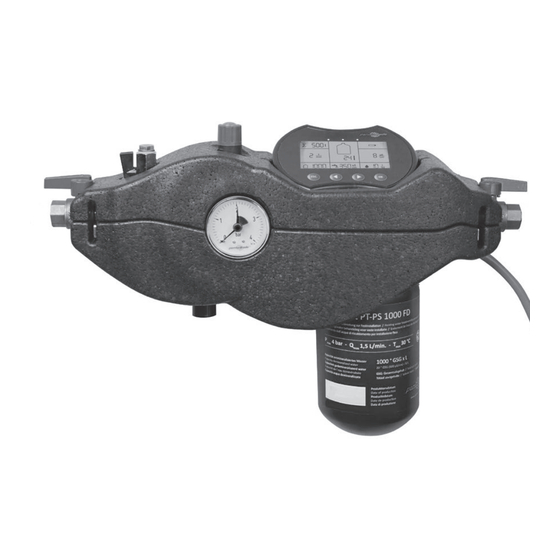
    3. LIEFERUMFANG PT-DA1000 / 5000 bzw. PT-DA-CH5000 PT-DB1000 / 5000 und PT-DBP1000 / 5000 * Bestehend aus: Bestehend aus: Entmineralisierungseinheit permasoft PT-PS1000FD / 5000FD Entmineralisierungseinheit permasoft PT-PS1000FD / 5000FD ① ① Separate ein- und ausgangsseitige Absperrventile Separate ein- und ausgangsseitige Absperrventile ②...
  • Seite 4: Einbaubedingungen

    4. EINBAUBEDINGUNGEN PT-FCS5000 und PT-FCSD5000 • Installation im Zulauf der Heizungsanlage dabei mind. 0,3 m Abstand zu Pumpen einhalten Bestehend aus: • Einbau in die waagrechte Rohrleitung mit Ablaufanschluss nach unten • Einbauort muss frostsicher und gut belüftet sein Entmineralisierungseinheit permasoft PT-PS5000FD ①...
  • Seite 5 6. GERÄTEMONTAGE Montage Digitale Heizungsbefüllstationen PT-DA und PT-DA-CH Durchflussrichtung beachten (Pfeil auf Befüllstation) 1. Haltebügel mittels beigefügtem Schraubenset ⑤ an der Wand befestigen (Abb.1) Abb. 1 Abb. 2 2. Kugelhähne mit Digitaler Heizungsbefüllstation verschrauben (Abb.2) ② 3. permasoft PT-PS1000 / 5000FD von unten ①...
  • Seite 6 ③ ⑤ ⑥ ② ④ Montage Digitale Heizungsbefüllstationen PT-DB(P) ② Durchflussrichtung beachten (Pfeil auf Befüllstation) ① 1. Haltebügel mittels beigefügtem Schraubenset ⑤ an der Wand befestigen (Abb.1) Abb. 1 Abb. 2 2. Manometer und gegenüberliegenden Blindstopfen auf Systemtrenner montieren ⑥ 3.
  • Seite 7 Montage Digitale Heizungsbefüllstationen PT-FCS(D)5000 Durchflussrichtung beachten (Pfeil auf Befüllstation) 1. Haltebügel mittels beigefügtem Schraubenset an der Wand befestigen und ⑤ rückwärtige Isolierschale auf den Haltbügel aufschieben (Abb.1) ⑤ 2. Manometer und gegenüberliegenden Blindstopfen auf Systemtrenner montieren ⑥ Abb. 1 Abb. 2 3.
  • Seite 8: Anschlüsse Für Signal- Und Impulsausgang

    ANSCHLÜSSE FÜR SIGNAL- UND IMPULSAUSGANG ANSCHLÜSSE FÜR SIGNAL- UND IMPULSAUSGANG Über den Signal-Ausgang (R wie Relais) kann die Digitale Heizungsbefüllstation in ein Über den Impuls-Ausgang kann die Durchflussmenge der Digitalen Heizungsbefüllstation Gebäudeleitsystem eingebunden werden. an eine externe Elektronik übermittelt werden. Bei Ausführungen mit Batterie PT-DA und PT-DB: 3 V / 0,1 A (VBAT) Bei allen Ausführungen: 3 V / 0,1 A (VBAT) Bei Ausführungen mit 24 V Netzteil PT-DBP und PT-FCS(D): 24 V / 0,1 A (VBAT)
  • Seite 9 7. INBETRIEBNAHME Bedienfeld PT-DA / PT-DB / PT-DBP Optische Leitfähigkeitsanzeige Inbetriebnahme PT-DA1000/5000, PT-DA-CH5000, PT-DB1000/5000, LF< 20 µS/cm: grün / 20 µS/cm< LF< 40 µS/cm: gelb / LF> 40 µS/cm: rot PT-DBP1000/5000 Elektronischer Wasserzähler Restkapazität Leitfähigkeit Rohwasser Batteriezustand / bei Heizungswasserbefüllstation auf ordnungsgemäße Installation überprüfen: kumulierte Nachfüllmenge...
  • Seite 10 Inbetriebnahme PT-FCS5000 * Bei der permasoft Version PT-PS1000FD darf der Volumenstrom bei der Nachspeisung maximal 2 l/ min betragen, da sonst zunehmend Salze aus dem Trinkwasser durchbrechen. Heizungswasserbefüllstation auf ordnungsgemäße Installation überprüfen: ** Bei einer Erstbefüllung mit PT-PS18000 bzw. PT-PS18000Alu muss die Nachspeiseüber wachung vor- 1.
  • Seite 11 Bedienfeld PT-FCS / PT-FCSD Inbetriebnahme PT-FCSD5000 Heizungswasserbefüllstation auf ordnungsgemäße Installation in Verbindung mit einem Optische Leitfähigkeitsanzeige LF< 20 µS/cm: grün / 20 µS/cm< LF< 40 µS/cm: gelb / LF> 40 µS/cm: rot Druckhaltsystem überprüfen: Leitfähigkeit Rohwasser Nachspeiseintervall / 1. Kugelhähne beidseitig schließen. Elektronischer Wasserzähler Restkapazität kumulierte Nachfüllmenge...
  • Seite 12: Instandhaltung

    8. INSTANDHALTUNG Anzeige und Tasten Alle relevanten Daten und Parameter sind gleichzeitig in der Anzeige sichtbar. Mit den Pfeiltasten wird der Wert der Einstellparameter vergrößert (rechte Pfeiltaste) bzw. Auswechseln von permasoft PT-PS1000FD / 5000FD / 18000 / 18000Alu/ 28000E verkleinert (linke Pfeiltaste). Wird eine Taste länger als 1 Sek. gedrückt gehalten, verändert 1.
  • Seite 13: Funktionskontrolle / Wartung Systemtrenner

    Funktionskontrolle / Wartung Systemtrenner Nachfüllwasserüberwachung/ -begrenzung Diese Einstellung definiert die maximal erlaubte Menge an Nachfüllwasser pro Woche. Wird Einbau- und Wartungsanweisung für Nachfüllkombination der eingestellte Wert erreicht, aktiviert sich bei PT-FCS / PT-FCSD das akustische Signal und Die Instandhaltung von Systemtrennern darf nur durch autorisiertes Fachpersonal erfolgen der Relaisausgang.
  • Seite 14: Technische Daten

    10. TECHNISCHE DATEN 11. STÖRUNGEN STÖRUNG URSACHE BEHEBUNG PT-DA PT-DA PT-DA-CH PT-DB PT-DB PT-DBP PT-DBP PT-FCS PT-FCSD 1000 5000 5000 1000 5000 1000 5000 5000 5000 kein oder zu wenig Systemtrenner nicht in Systemtrenner in Durchfluss Durchflussrichtung Durchflussrichtung Versorgungsspannung in V DC / Batterie montiert montieren (Pfeilrichtung auf 2 x AA...
  • Seite 15: Eg-Konformitätserklärung

    Bauteile. werbebereich sowie die Einhaltung der im Folgenden aufgelisteten Normen und Richtlinien wird hiermit bestätigt (CE Konformität). EN 60335-1 WEEE-Reg.-Nr. DE 91509671 Die permasoft Entmineralisierungseinheit kann an den Hersteller perma-trade EG-Richtlinie: Beschränkung der Verwendung bestimmter 2011/65/EU Wassertechnik zurückgesandt werden und wird dort anschließend recycelt.
  • Seite 16: Productomschrijving

    Voor het overige zijn beide versies identiek. PT-DA1000 / PT-DA5000 / PT-DA-CH5000 Digitaal verwarmingsvularmatuur PT-DA1000 / 5000 en PT-DA-CH5000 bestaande uit aparte PT-FCS-IT / PT-FCSD-IT afsluitkleppen aan in- en uitgangszijde, elektronica (Batterij 3 V) met 4-inch-display, water- De twee versies PT-FCS-IT en PT-FCSD-IT zijn alleen verkrijgbaar als onderdeel van de per- meter en geleidingsmeting, isolatieschalen en permasoft.
  • Seite 17 3. LEVERINGSOMVANG PT-DA1000 / 5000 en PT-DA-CH5000 PT-DB1000 / 5000 en PT-DBP1000 / 5000* Bestaande uit: Bestaande uit: Demineraliseringseenheid permasoft PT-PS1000FD / 5000FD Demineraliseringseenheid permasoft PT-PS1000FD / 5000FD ① ① Aparte afsluitkleppen aan in- en uitgangszijde Aparte afsluitkleppen aan in- en uitgangszijde ②...
  • Seite 18 4. MONTAGEVOORWAARDEN PT-FCS5000 en PT-FCSD5000 • Installatie in de toevoer van de verwarmingsinstallatie daarbij min. 0,3 m afstand tot pompen Bestaande uit: behouden • Montage in de horizontale buisleiding met afloopaansluiting naar beneden Demineraliseringseenheid permasoft PT-PS5000FD ① • Montagelocatie moet vorstbestendig en goed verlucht zijn Aparte afsluitkleppen aan in- en uitgangszijde ②...
  • Seite 19 6. TOESTELMONTAGE Montage Digitaal verwarmingsvularmatuur PT-DA en PT-DA-CH Let op de stroomrichting (pijl op het vulstation). 1. Bevestig de beugel aan de muur met de bijgeleverde schroefset aan de muur (Afb.1) ⑤ Afb. 1 Afb. 2 2. Schroefkogelkranen naar digitaal verwarmings vulstation (Afb.2) ②...
  • Seite 20 ③ ⑤ ⑥ ② ④ Montage Digitaal verwarmingsvulstation PT-DB(P) ② Let op de stroomrichting (pijl op het vulstation). 1. Bevestig de beugel aan de muur met de bijgeleverde ⑤ ① schroefset aan de muur (Afb.1) Afb. 1 Afb. 2 2. Plaats de manometer en de tegenoverliggende afsluitdop op de systeemscheider ⑥...
  • Seite 21 Montage Digitaal verwarmingsvulstation PT-FCS(D)5000 ⑦ ③ ⑥ ⑤ ② Let op de stroomrichting (pijl op het vulstation). ④ ② 1. Bevestig de bevestigingsbeugel aan de muur met ⑤ de bijgeleverde tegen de muur en duw de achterste isolatieschaal op de bevestigingsbeugel (Afb.1) Afb.
  • Seite 22 AANSLUITINGEN VOOR SIGNAAL EN PULS UITGANG AANSLUITINGEN VOOR SIGNAAL EN PULS UITGANG Het digitale verwarmingsvulstation kan via de signaaluitgang (R voor relais) in een gebou- Het debiet van het digitale verwarmingsvulstation kan via de pulsuitgang worden doorge- wbeheersysteem worden geïntegreerd. geven aan externe elektronica.
  • Seite 23: Ingebruikname

    Bedieningsveld PT-DA / PT-DB / PT-DBP 7. INGEBRUIKNAME Optische weergave geleidbaarheid LF< 20 µS/cm: groen / 20 µS/cm< LF< 40 µS/cm: geel / LF> 40 µS/cm: rood Ingebruikname PT-DA1000/5000, PT-DB1000/5000, PT-DBP1000/5000 Verwarmingswatervulstation op reglementaire installatie controleren: Elektronische watermeter Restcapaciteit Geleidbaarheid niet...
  • Seite 24 Ingebruikname PT-FCS5000 * Bij de permasoft versie PT-PS1000FD mag het debiet bij de latere toevoer maximaal 2 l/min bedragen aangezien anders toenemend zouten uit het tapwater doorbreken. Verwarmingswatervulstation op reglementaire installatie controleren: ** Bij een eerste vulling met PT-PS18000 resp. PT-PS18000Alu moet de latere toevoercontrole tijdelijk 1.
  • Seite 25 Bedieningsveld PT-FCS / PT-FCSD Ingebruikname PT-FCSD5000 Optische weergave geleidbaarheid LF< 20 µS/cm: groen / 20 µS/cm< LF< 40 µS/cm: geel / LF> 40 µS/cm: rood Verwarmingswatervulstation op reglementaire installatie in combinatie met drukbe- houdsysteem controleren. Elektronische watermeter Restcapaciteit Geleidbaarheid niet Interval latere toevoer / gecumuleerde navulhoeveelheid permasoft...
  • Seite 26: Technische Instructies

    8. ONDERHOUD Indicatie en toetsen Alle relevante gegevens en parameters zijn tegelijk in de indicatie zichtbaar. Uitwisselen van permasoft PT-PS1000FD / 5000FD / 18000 / 18000Alu/ 28000E Met de pijltjestoetsen wordt de waarde van de instelparameter vergroot (rechtse pijltjes- toets) resp. verkleind (linkse pijltjestoets). Wordt een toets langer dan 1 sec. ingedrukt ge- 1.
  • Seite 27 Functiecontrole / onderhoud systeemscheider Navulwatercontrole/ -begrenzing Deze instelling bepaalt de maximaal toegestane hoeveelheid navulwater per week. Wanneer Inbouw- en onderhoudsaanwijzing voor navulcombinatie de ingestelde waarde wordt bereikt, activeert de PT-FCS / PT-FCSD het akoestische signaal en Het onderhoud van systeemscheiders mag enkel door geautoriseerd vakpersoneel gebeuren de relaisuitgang.
  • Seite 28: Technische Gegevens

    10. TECHNISCHE GEGEVENS 11. STORINGEN STORING OORZAAK OPLOSSING PT-DA PT-DA PT-DA-CH PT-DB PT-DB PT-DBP PT-DBP PT-FCS PT-FCSD TYPE 1000 5000 5000 1000 5000 1000 5000 5000 5000 geen of te weinig debiet Systeemscheider niet in Systeemscheider in doorstroomrichting doorstroomrichting Toevoerspanning in V DC / batterij gemonteerd monteren (pijlrichting op behui-...
  • Seite 29: Instructies Voor Afvoer

    (CE conformiteit). EN 60335-1 WEEE-Reg.-nr. NL / B 91509671 EG-richtlijn: Beperking van het gebruik van bepaalde 2011/65/EU De permasoft demineraliseringseenheid kan aan de fabrikant perma-trade gevaarlijke stoffen in elektro- en elektronische Wassertechnik worden teruggestuurd en wordt daar vervolgens gerecycled. apparaten (RoHS) Rechtsbindende handtekening: ______________________________ Dr.
  • Seite 30: Consigne De Sécurité

    PT-PS28000E. Les PT-DA1000/5000 sont prévus pour les objets dans lesquels un séparateur de système Ligne de signalisation sans potentiel (open collector) pour l’intégration dans la gestion tech- conforme à...
  • Seite 31: Contenu De La Livraison

    3. CONTENU DE LA LIVRAISON PT-DA1000 / PT-DA5000 / PT-DACH5000 PT-DB1000 / 5000 et PT-DBP1000 / 5000* Composé de : Composé de : PT-DB1000 Unité de déminéralisation permasoft PT-PS1000FD / 5000FD ① Unité de déminéralisation permasoft PT-PS1000FD / 5000FD ①...
  • Seite 32: Conditions De Montage

    4. CONDITIONS DE MONTAGE PT-FCS5000 et PT-FCSD5000 • Installation au niveau de l'alimentation du système de chauffage respecter une distance d'au Composé de : moins 0,3 m des pompes. • Montage dans la conduite horizontale avec raccord d’évacuation vers le bas Unité...
  • Seite 33: Montage De L'appareil

    6. MONTAGE DE L’APPAREIL Montage de station de remplissage de chauffage numérique PT-DA und PT-DA-CH Prendre en compte la direction d’écoulement (flèche sur la station de remplissage) 1. Fixer l’étrier de blocage au mur à l’aide du jeu de vis joint ⑤...
  • Seite 34 Montage de station de remplissage de chauffage numérique PT-DB(P) Prendre en compte la direction d’écoulement (flèche sur la station de remplissage) 1. Fixer l’étrier de blocage au mur à l’aide du jeu de vis joint (Fig.1) ⑤ 2. Monter le manomètre et les bouchons obturateurs opposés sur le séparateur de système Fig.
  • Seite 35 Montage de station de remplissage de chauffage numérique PT-FCS(D)5000 Prendre en compte la direction d’écoulement (flèche sur la station de remplissage) 1. Fixer l’étrier de blocage au mur à l’aide du jeu de vis joint (Fig.1) et la coque isolante ⑤...
  • Seite 36 CONNEXIONS POUR LA SORTIE DE SIGNAL ET CONNEXIONS POUR LA SORTIE DE SIGNAL ET D‘IMPULSION D‘IMPULSION La sortie d‘impulsion permet de transmettre le débit de la station numérique de remplis- Grâce à la sortie de signal (R comme relais), la station numérique de remplissage de chauf- sage de chauffage à...
  • Seite 37: Mise En Service

    Affichage optique de la conductivité LF< 20 µS/cm : vert / 20 µS/cm< LF< 40 µS/cm : jaune / LF> 40 µS/cm : rouge Mise en service PT-DA1000/5000, PT-DB1000/5000, PT-DBP1000/5000 Vérifier que la station de remplissage de chauffage est correctement installée : État de la batterie...
  • Seite 38 Mise en service PT-FCS5000 * Avec la version permasoft PT-PS1000FD, le débit volumétrique lors de la réalimentation ne doit pas dépasser 2 l/min, sinon les sels de l'eau potable passeront de plus en plus au travers. Vérifier que la station de remplissage de chauffage est correctement installée : ** Lors du premier remplissage avec le PT-PS18000 ou le PT-PS18000Alu, la surveillance de réalimen- 1.
  • Seite 39 Panneau de commande PT-FCS / PT-FCSD Mise en service PT-FCSD5000 Affichage optique de la conductivité Vérifier que la station de remplissage de chauffage associée à un système de maintien en LF< 20 µS/cm : vert / 20 µS/cm< LF< 40 µS/cm : jaune / LF> 40 µS/cm : rouge pression soit correctement installée : Intervalle d’appoint / pour...
  • Seite 40: Indications Techniques

    8. MAINTENANCE Affichage et touches Toutes les données et paramètres importants sont visibles simultanément sur l’affichage. Avec les touches fléchées, la valeur du paramètre de réglage est grossie (touche fléchée droite) Remplacement du permasoft PT-PS1000FD / 5000FD / 18000 / 18000Alu/ 28000E ou réduite (touche fléchée gauche) Si la pression sur une touche dure plus d’1 seconde, la va- 1.
  • Seite 41 Contrôle fonctionnel / maintenance séparateur de système Surveillance/ Limitation de l’eau d’appoint Ce réglage définit la quantité maximale d’eau d’appoint autorisée par semaine. Instruction de montage et d’entretien pour la combinaison d’appoint Si la valeur paramétrée est atteinte, le signal acoustique et la sortie relais s’activent pour les La maintenance de séparateurs doit être uniquement réalisée par du personnel spécialisé...
  • Seite 42: Caractéristiques Techniques

    10. CARACTÉRISTIQUES TECHNIQUES 11. DYSFONCTIONNEMENTS DYSFONCTIONNEMENT CAUSE ÉLIMINATION PT-DA PT-DA PT-DA-CH PT-DB PT-DB PT-DBP PT-DBP PT-FCS PT-FCSD TYPE 1000 5000 5000 1000 5000 1000 5000 5000 5000 aucun débit ou débit le séparateur n'est pas monter le séparateur dans le insuffisant monté...
  • Seite 43: Déclaration Ce De Conformité

    : tances dangereuses dans les appareils élec- triques et électroniques (RoHS) L'unité de déminéralisation permasoft peut être retournée au fabricant perma-Trade Wassertechnik pour y être recyclée. Signature juridiquement obligatoire : ______________________________ Dr. D.Ende, Head of Research and Development Cette déclaration certifie la conformité avec les directives citées, ne contient toutefois aucune garantie de propriétés.
  • Seite 44: Scopo Di Utilizzo

    Linea di segnale a potenziale zero (collettore aperto) per l’integrazione nel sistema di gestione I PT-DA1000/5000 sono progettati per oggetti in cui è già installato un separatore di sistema degli edifici. conforme alla norma EN1717. I PT-DA-CH5000 sono progettati per un collegamento tempo- Uscita a impulsi (collettore aperto) per la trasmissione del volume d’acqua da reintegrare.
  • Seite 45 3. FORNITURA PT-DA1000 / 5000 e PT-DA-CH5000 PT-DB1000 / 5000 e PT-DBP1000 / 5000 * Costituita da: Costituita da: Gruppo di demineralizzazione permasoft PT-PS1000FD / 5000FD Gruppo di demineralizzazione permasoft PT-PS1000FD / 5000FD ① ① Valvole di chiusura separate sul lato d’ingresso e d’uscita Valvole di chiusura separate sul lato d’ingresso e d’uscita...
  • Seite 46: Condizioni Di Installazione

    4. CONDIZIONI DI INSTALLAZIONE PT-FCS5000 / PT-FCSD5000 • Installazione nella mandata dell’impianto di riscaldamento mantenendo almeno 0,3m di Costituita da: distanza dalle pompe • Installazione nella tubazione orizzontale con collegamento di scarico verso il basso Gruppo di demineralizzazione permasoft PT-PS1000FD / 5000FD ①...
  • Seite 47: Montaggio Del Dispositivo

    ③ ⑤ ④ 6. MONTAGGIO DEL DISPOSITIVO ② ② Montaggio PT-DA e PT-DA-CH5000 Rispettare la direzione del flusso (freccia sul gruppo di riempimento) ① IT IT IT IT 1. Fissare la staffa alla parete tramite il kit di ⑤ ill. 1 ill.
  • Seite 48 Montaggio PT-DB(P) Rispettare la direzione del flusso (freccia sul gruppo di riempimento) 1. Fissare la staffa alla parete tramite il kit di viti fornite (ill.1) ⑤ 2. Montare il manometro e il tappo di chiusura opposto sul separatore del sistema. ⑥...
  • Seite 49 Montaggio PT-FCS(D)5000 Rispettare la direzione del flusso (freccia sul gruppo di riempimento) 1. Fissare la staffa alla parete tramite il kit di viti fornite (ill.1) e spingere il guscio ⑤ isolante posteriore sulla staffa di fissaggio ⑤ 2. Montare il manometro e il tappo di chiusura opposto sul separatore del sistema.
  • Seite 50 CONNESSIONI PER L‘USCITA DEL SEGNALE E DEGLI IMPULSI CONNESSIONI PER L‘USCITA DEL SEGNALE E DEGLI IMPULSI Gruppo di rabbocco digitale dell’impianto di riscaldamento può essere integrata in un siste- La portata della gruppo di rabbocco digitale dell’impianto di riscaldamento può essere tras- ma di gestione dell‘edificio tramite l‘uscita di segnale (R per relè).
  • Seite 51: Messa In Servizio

    7. MESSA IN SERVIZIO Pannello di comando PT-DA / PT-DB / PT-DBP Indicazione ottica della conducibilità Messa in servizio PT-DA1000/5000, PT-DA-CH5000, PT-DB1000/5000, < 20 µS/cm verde / < 40 µS/cm giallo / > 40 µS/cm rosso PT-DBP1000/5000 Stato della batteria / Controllare la corretta installazione del gruppo di rabbocco dell’impianto di riscaldamento:...
  • Seite 52: Messa In Servizio Pt-Fcs5000

    Messa in servizio PT-FCS5000 Pannello di comando PT-FCS / PT-FCSD Controllare la corretta installazione del gruppo di rabbocco dell’impianto di riscaldamento: Indicazione ottica della conducibilità < 20 µS/cm verde / < 40 µS/cm giallo / > 40 µS/cm rosso 1. Chiudere le valvole a sfera su entrambi i lati. Contatore dell’acqua elettronico 2.
  • Seite 53: Messa In Servizio Pt-Fcsd 5000

    8. MANUTENZIONE Messa in servizio PT-FCSD 5000 Controllare la corretta installazione del gruppo di rabbocco dell’impianto di riscaldamento con un sistema di mantenimento pressione: Sostituzione di permasoft PT-PS 1000 / 5000 /18000 /18000 ALU / 28000 1. Chiudere le valvole a sfera su entrambi i lati 1.
  • Seite 54 Display e tasti Controllo/ limitazione dell’acqua di riempimento Tutti i dati e parametri rilevanti sono visibili contemporaneamente sul display. L’impostazione definisce la quantità massima consentita settimanale dell’acqua di riempi- Con i tasti freccia vengono aumentati (tasto destro) o diminuiti (tasto freccia sinistra) i valori mento.
  • Seite 55 10. TECHNISCHE DATEN Controllo di funzionamento / Manutenzione del disconnettore d‘impianto Indicazioni di installazione e manutenzione per gruppi di riempimento con disconnettore PT-DA PT-DA PT-DA-CH PT-DB PT-DB PT-DBP PT-DBP PT-FCS PT-FCSD TIPO 1000 5000 5000 1000 5000 1000 5000 5000 5000 La manutenzione dei disconnettori del sistema può...
  • Seite 56: Indicazioni Per Lo Smaltimento

    Smontare e pulire o sostituire (nessuna oscillazione d’ingresso o la valvola di al produttore perma-trade. l’inserto della cartuccia della pressione di scarico imbrattate La tecnologia dell'acqua verrà restituita e quindi riciclata lì.
  • Seite 57: Dichiarazione Di Conformità Ce

    DICHIARAZIONE DI CONFORMITÀ CE Produttore: perma-trade Wassertechnik GmbH Indirizzo: Röntgenstraße 2 71229 Leonberg Descrizione del prodotto • PT-DA Dispositivo di riempimento del riscaldamento digitale (3 V) senza disconnetore di sistema • PT-DB Gruppo di rabbocco di riscaldamento digitale (3 V) con disconnettore di sistema •...
  • Seite 58: Purpose Of Use

    Here, the built-in solenoid valve is always open and closes only in case of demand/signaling. Otherwise, both versions are identical. PT-DA1000 / PT-DA5000 PT-DA-CH5000 PT-DA1000 / 5000 and PT-DA-CH5000 digital heating filling fitting, consisting of separate PT-FCS-IT / PT-FCSD-IT shut-off valves on the inlet and outlet sides, battery-operated electronics with 4-inch display, The two versions PT-FCS-IT and PT-FCSD-IT are only available as part of the permaLine inte- water meter and conductance measurement, insulating shells and permasoft.
  • Seite 59: Scope Of Delivery

    3. SCOPE OF DELIVERY PT-DA1000 / 5000 and PT-DA-CH5000 PT-DB1000 / 5000 and PT-DBP1000 / 5000 * Consisting of: Consisting of: PT-PS1000FD / 5000FD permasoft demineralisation unit PT-PS1000FD / 5000FD permasoft demineralisation unit ① ① Separate shut-off valves on the inlet and outlet sides Separate shut-off valves on the inlet and outlet sides ②...
  • Seite 60: Installation Conditions

    4. INSTALLATION CONDITIONS PT-FCS5000 and PT-FCSD5000 • Installation in the inlet of the heating system, maintaining a minimum distance of 0.3 m Consisting of: to pumps • Installation in the horizontal pipe with the drain connection facing downwards PT-PS5000FD permasoft demineralisation unit ①...
  • Seite 61: Device Installation

    6. DEVICE INSTALLATION Installation of digital heating filling stations PT-DA and PT-DA-CH Observe the flow direction (arrow on filling station) 1. Fasten the holding bracket to the wall with the screw set provided (fig.1) ⑤ Fig. 1 Fig. 2 2 Screw the ball valves on (fig.2) ②...
  • Seite 62 Installation of digital heating filling stations PT-DB(P) Observe the flow direction (arrow on filling station) 1. Fasten the holding bracket to the wall with the screw set provided (fig.1) ⑤ 2. Mount pressure gauge and opposite blanking plug on system separator ⑥...
  • Seite 63 Installation of digital heating filling stations PT-FCS(D)5000 Observe the flow direction (arrow on filling station) 1. Fasten the holding bracket to the wall with the screw set provided (fig.1) and push rear ⑤ insulating shell onto the retaining bracket 2. Mount pressure gauge and opposite blanking plug on system separator ⑥...
  • Seite 64 CONNECTIONS FOR SIGNAL AND PULSE OUTPUT CONNECTIONS FOR SIGNAL AND PULSE OUTPUT The digital heating filling station can be integrated into a building control system via the The pulse output can be used to transmit the flow rate of the Digital Heater Filling Station signal output (R for relay).
  • Seite 65 7.COMMISSIONING PT-DA / PT-DB / PT-DBP control panel Optical conductance display Commissioning of PT-DA1000/5000, PT-DA-CH5000, PT-DB1000/5000, conductance < 20 µS/cm: green / 20 µS/cm < conductance < 40 µS/cm: yellow / conductance > 40 µS/cm: red PT-DBP1000/5000 Raw water conductance...
  • Seite 66 Commissioning the PT-FCS5000 * With the permasoft version PT-PS1000FD, the flow rate for the refilling must not exceed 2 l/min, as otherwise salts will increasingly break through from the drinking water. Check that the heating water filling station has been installed properly: ** When filling for the first time in the case of the PT-PS18000 or PT-PS18000Alu, the refill monitoring 1.
  • Seite 67 PT-FCS / PT-FCSD control panel Commissioning the PT-FCSD5000 Check that the heating water filling station has been installed properly in conjunction with a Optical conductance display conductance < 20 µS/cm: green / 20 µS/cm < conductance < 40 µS/cm: yellow / conductance > 40 µS/cm: red pressure holding system: Raw water conductance Refilling interval /...
  • Seite 68: Technical Notes

    8. MAINTENANCE Display and keys All relevant data and parameters are visible simultaneously on the display. Using the arrow keys, the values of the setting parameters are increased (right arrow key) Exchange of permasoft with PT-PS1000FD / 5000FD / 18000 / 18000Alu/ 28000E or decreased (left arrow key).
  • Seite 69 Refilling water monitoring/limitation Function check/maintenance of the system separator This setting defines the maximum permitted quantity of refilling water per week. In the case Installation and maintenance instructions for refilling combination of the PT-FCS / PT-FCSD, the acoustic signal and relay output are activated if the set value is The maintenance of system separators may only be done by authorised technical personnel reached.
  • Seite 70: Technical Data

    10. TECHNICAL DATA 11. FAULTS FAULT CAUSE REMEDIAL MEASURE PT-DA PT-DA PT-DA-CH PT-DB PT-DB PT-DBP PT-DBP PT-FCS PT-FCSD TYPE 1000 5000 5000 1000 5000 1000 5000 5000 5000 Flow rate too low or no System separator not Install the system separator flow at all mounted in the flow direc- in the flow direction (observe...
  • Seite 71: Ec Conformity Declaration

    (CE conformity). EN 60335-1 The permasoft demineralisation unit can be returned to the manufacturer, perma-trade Wassertechnik GmbH, where it will subsequently be recycled. EC directive: Limitation of the use of certain hazardous...
  • Seite 73 Aqua-Partner · 5, rue Brûlée · 67620 Soufflenheim Tél. 06.75.38.69.55 aqua.partner@outlook.fr · www.aquapartner.fr perma-trade Italia S.r.l. · Via C. Maffei, 3 · 38089 Darzo (TN) Tel. + 39 04 65 68 47 01 · Fax:+ 39 04 65 68 40 66 www.perma-trade.it · info@perma-tradeitalia.it...

Inhaltsverzeichnis