
Verwandte Anleitungen für Wohler VIS 36/42

Inhaltszusammenfassung für Wohler VIS 36/42
- Seite 1 Bedienungsanleitung Kamerahaspel 36/42 Operation Manual Camera Viper 36/42 Mode d‘emploi Dévidoir 36/42 Istruzioni d‘uso Aspo telecamera Wöhler VIS...
-
Seite 2: Inhaltsverzeichnis
Inhalt Inhalt Allgemeines ........... 3 Informationen zur Bedienungsanleitung ..3 Hinweise in der Bedienungsanleitung ... 3 Bestimmungsgemäße Verwendung ....3 Herstelleranschrift ......... 3 Technische Daten ......... 4 Aufbau ............ 5 Anschlüsse ..........7 Anschluss des Kamerakopfes ....... 7 Anschluss der Monitore ......... 7 Einstellen der Freilaufbremse ..... -
Seite 3: Allgemeines
Allgemeines Allgemeines Informationen zur Diese Bedienungsanleitung ermöglicht Ihnen die sichere Bedienung der Kamerahaspel 36/42. Be- Bedienungsanleitung wahren Sie diese Bedienungsanleitung dauerhaft auf. Die Kamerahaspel darf grundsätzlich nur von fachkundigem Personal für den bestimmungsge- mäßen Gebrauch eingesetzt werden. Für Schä- den, die aufgrund der Nichtbeachtung dieser Be- dienungsanleitung entstehen, übernehmen wir keine Haftung. -
Seite 4: Technische Daten
Technische Daten Technische Daten Korb Durchmesser Kamerahaspel 42 42 cm Kamerahaspel 36 36 cm Breite 10 cm Drehübertragung Bis 30 m Gewicht ohne Stange 2 kg Verbindungskabel 2,5 m lang zum Monitor Integrierte Meterzählung Funktionsprinzip digital Auflösung 0,05 m Messbereich 0 –... -
Seite 5: Aufbau
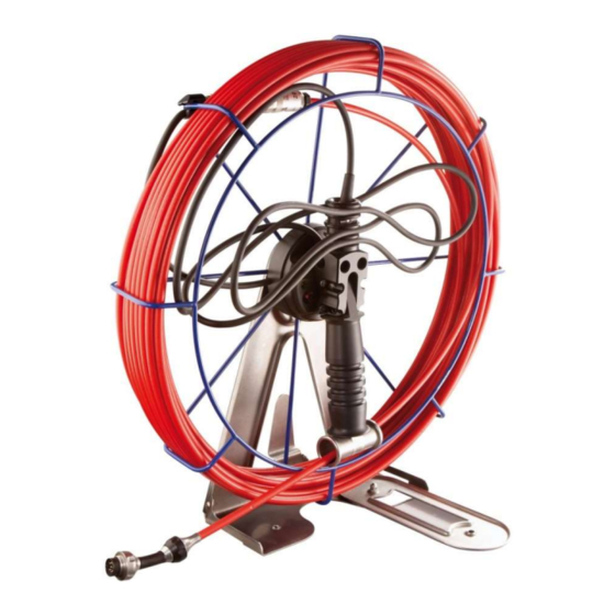
Aufbau Aufbau Abb. 1: Kamerahaspel, Ansicht von vorne Legende Bedientaste (Nullstellung, Parameterein- gabe) Kabelhalterung Steckerschutz Klappfuß Klappgriff Stangendurchführung Monitor-Anschluss (nicht sichtbar, da zum Transport in den Steckerschutz einge- steckt) Anschluss Kamerakopf... - Seite 6 Aufbau Abb. 2: Kamerahaspel, Ansicht von hinten Legende Einstellschraube Freilaufbremse 10 Koppelhalterung...
-
Seite 7: Anschlüsse
Anschlüsse Anschlüsse Anschluss des Alle Wöhler Kameraköpfe verfügen über eine 8- polige Kupplungs-Buchse, über die sie mit der Kamerakopfes Haspel verbunden werden (8-poligen Kabelste- cker). Stecken Sie die Kupplungs-Buchse des Ka- merakopfes auf den Kamerakopf-Anschluss des Kamerakabels (Abb. 1, Teil 8) und drehen Sie anschließend das Gewindestück an der Haspel zum Verschließen im Uhrzeigersinn. -
Seite 8: Einstellen Der Freilaufbremse
Einstellen der Freilaufbremse Einstellen der Die Kamerahaspel ist mit einer Freilaufbremse ausgestattet. Dadurch wird die GFK-Stange beim Freilaufbremse Auf- und Abwickeln kontrolliert und läuft nicht selb- ständig aus der Haspel. Die Bremse ist mit folgen- der Funktionalität ausgestattet: Rechtslauf leicht (ohne Bremswirkung) > Stangen- einlauf Linkslauf schwer oder leicht (mit Bremswirkung je nach Einstellung) >... - Seite 9 Inspektion Die Haspel wird während der Inspektion mittels Koppelhalterung am Koppelgürtel getragen. So bleiben beide Hände frei für die Bedienung des Monitors und die Füh- rung der Stange. Abb. 5: Haspel am Koppelgürtel getragen Die Haspel kann auf den Boden gestellt werden, sobald der Haspelfuß...
-
Seite 10: Nach Der Inspektion
Nach der Inspektion Nach der Nach der Inspektion lösen Sie das Monitoran- schlusskabel vom Monitor und klemmen Sie Inspektion es in Schlaufen in die Kabelhalterung. Stecken Sie den Monitor-Anschluss in den Steckerschutz. Dort wird er bei Transport und Lagerung vor Verschmutzung oder Mechani- schen Schäden geschützt. - Seite 11 Stangenwechsel sichtig zurück. Führen Sie die Kupplungsbuchse der neuen Stange durch die Öse zur Steckeraufnahme und verbinden Sie sie mit dem Stecker der Haspel. Wickeln Sie die Stange linksherum auf. ACHTUNG! Achten Sie beim Hereinschieben der Stange da- rauf, dass sie sich gleichmäßig über die Breite des Haspelkorbes aufwickelt.
-
Seite 12: Wartung Und Pflege
Wartung und Pflege Wartung und Pflege Reinigen Sie die Haspel mit einem feuchten Tuch und ggf. einem milden Reinigungsmittel. Achten Sie dabei unbedingt darauf, dass kein Wasser in den Bereich der Meterzählung dringt. WARNUNG! Das Gerät ist vor dem Öffnen von jeglicher Span- nungsquelle (Monitoreinheit etc.) zu trennen. -
Seite 13: Gewährleistung Und Service
Gewährleistung und Service Gewährleistung und Service 11.1 Gewährleistung Jede Kamerahaspel 36/42 wird im Werk in allen Funktionen geprüft und verlässt unser Werk erst nach einer ausführlichen Qualitätskontrolle. Bei sachgemäßem Gebrauch beträgt die Gewähr- leistungszeit auf die Kamerahaspel 12 Monate ab Verkaufsdatum., Diese Gewährleistung erlischt, wenn Reparaturen und Abänderungen von dritter, nicht autorisierter... - Seite 14 Contents Contents General Information ......15 Operation Manual Information ..... 15 Notes ............15 Proper use ........... 15 Manufacturer ..........15 Technical Data ........16 Component explanation ..... 17 Belt support ......... 19 Connecting the camera head ...... 19 Connecting the monitor ....... 19 Adjusting the freewheel brake ...
-
Seite 15: General Information
General Information General Information Operation Manual This operation manual allows you to work safely with the Camera Viper 36/42. Please keep this Information manual for your information. The Wöhler Camera Viper is to be used by pro- fessionally trained personnel exclusively for the purpose for which it was designed. -
Seite 16: Technical Data
Technical Data Technical Data Basket Diameter Camera Viper 42 42 cm Camera Viper 36 36 cm Width: 10 cm Transmittance up to 30 m Weight (without rod) 2 kg Connection cable to 2.5 m the monitor Integrated metric marking Functional principle digital Resolution 0.05 m... -
Seite 17: Component Explanation
Component explanation Component explanation Fig. 10: Camera Viper, front view Explanation Button (Reset to zero and input of param- eters) Cable support Jacket protection Retractable viper stand Grip Rod duct Connection to monitor (not visible here) Connection to the camera head... - Seite 18 Component explanation Fig. 11: Camera Viper, back view Explanation Adjusting screw for free-wheel bracket 10 Belt clip...
-
Seite 19: Belt Support
Belt support Belt support Connecting the camera All Wöhler camera-heads are connected via a clutch socket with 8 poles to the camera viper head (cable jack with 8 poles). Plug camera head and camera cable together and then turn the thread clockwise for closing the screw connection tightly. -
Seite 20: Inspection
Inspection Inspection WARNING! Guide the rod with due care and attention. As the rod is made of flexible material, it can make whip- ping movements if it slips. Protect your eyes in particular. With the Camera Viper a vertical and a horizontal inspection of the ducts is possible. - Seite 21 Inspection You can carry the viper in your hand dur- ing the inspection. In this case you will have to pull out the grip. After the inspection, push the grip back, so that rod and camera head will be protected by the grip. The viper is smaller now and may easily be transported.
-
Seite 22: After The Inspection
After the inspection After the inspection After the inspection and after the connector cable has been pulled off, the connector cable can be clamped into the straps of the cable support. Put the jacket into the cable support for pro- tecting it against dust or mechanical defects. - Seite 23 Changing the rod CAUTION! When winding the rod, pay attention that it ex- tends the whole width of the cage. A winding on one side only, may provoke that the rod jumps out of the cage. Fix the free-wheel-bracket as described in point 5.
-
Seite 24: Care And Maintenance
Care and maintenance Care and Clean the viper with a damp cloth only, but never with water and cleaning agent. Clean maintenance the device with a wet cloth and a smooth cleanser. Pay attention that no water will enter the metric marking. -
Seite 25: Warranty And Service
Warranty and Service Warranty and Service 11.1 Warranty Each Wöhler Camera Viper 36/42 will be tested in all functions and will leave our factory only after extensive quality control testing. If used properly, the warranty period for the Wöh- ler Camera Viper will be twelve month from the date of sale. - Seite 26 Contenue Informations Générales ...... 27 Informations relatives au mode d'emploi ..27 Remarques ..........27 Utilisation conforme ........27 Fabricant ............. 27 Données techniques ......28 Déscription .......... 29 Raccords ..........31 Raccord de la tête de caméra ..... 31 Raccordement de l’écran ......
-
Seite 27: Informations Générales
Informations Générales Informations Générales Informations relatives Ce mode d'emploi vous permet de travailler en toute sécurité avec votre Dévidoir. Il doit être con- au mode d'emploi servé à titre d'information. Le Dévidoir ne peut être utilisé que par un per- sonnel dûment qualifié... -
Seite 28: Données Techniques
Données techniques Panier Diamètre Dévidoir pour câble de 42 cm caméra 42 Dévidoir pour câble de 36 cm caméra 36 Largeur 10 cm Transmission tournan- jusque‘à 30 m Poids (sans câble) 2 kg Câble de jonction á 2,5 m l’écran Compte-Mètres intégré... -
Seite 29: Déscription
Déscription Déscription Fig. 19: Dévidoir, vue de face Description 11 Touche de commande (position zéro, sai- sie des paramètres) 12 Fixation de câble 13 Protection de connecteur 14 Pied pliant 15 Poignée pliante 16 Passage du câble 17 Raccordement du câble au moniteur (pas visible sur la photo, car inséré... - Seite 30 Fig. 20: Dévidoir, vue de face Description 19 Vis de réglage du frein de roue libre 20 Clip pour ceinture...
-
Seite 31: Raccords
Raccords Raccords Raccord de la tête de Toutes les têtes de caméra Wöhler disposent d’une prise de connexion 8 pôles permettant de caméra les relier avec le dévidoir par un connecteur de câble 8 pôles. Raccordez la prise de la tête caméra avec le branchement du câble (voir fig. -
Seite 32: Inspection
Le fait de tourner la vis de réglage dans le sens horaire hausse le freinage. En sens inverse, le freinage diminue et la tige sort plus facilement du panier. L’utilisateur peut sortir le câble du panier plus facilement. Fig. - Seite 33 Inspection Il est possible de poser le dévidoir sur le sol dès que son pied a été déplié. Posez maintenant un pied sur celui du dé- vidoir pour garantir un bon maintien en équilibre pendant l‘utilisation. Fig. 24: Dévidoir posé sur le sol Pendant l‘utilisation, vous tenez le dévidoir en main.
-
Seite 34: Après L'inspection
Après l'inspection Après l‘inspection et après avoir défait le câble de raccordement du moniteur, il est possible de le loger en boucles dans la fixation à cet ef- fet. Pour protéger le connecteur contre les salis- sures ou tout endommagement mécanique, il est possible de l‘enfoncer en haut dans la fixa- tion de câble. - Seite 35 Remplacer le câble jusque‘à la butée. Faites passer la prise d‘accouplement du câble neuf par l‘œillet en direction du loge- ment de la fiche mâle puis reliez cette prise avec la fiche mâle du dévidoir. Maintenant, vous pouvez enrouler la tige en tournant dans le sens antihoraire.
- Seite 36 Si vous devez enrouler un câble d‘une autre lon- gueur, il faudra programmer ses paramètres. Pro- cédez de la manière suivante: Pendant l‘enclenchement du moniteur, ap- puyez pendant environ 3 secondes sur la touche de l‘enroulement puis relâchez-la en- suite.
-
Seite 37: Maintenance Et Soins D'entretien
Maintenance et soins d'entretien Maintenance et Nettoyer le dévidoir avec un chiffon légère- ment humide et un détergent doux. Veillez à soins d'entretien ce qu‘il ne pénètre jamais d‘eau dans la zone du compte-mètres. Danger! Avant d‘ouvrir l‘appareil, débranchez-le de toute source d‘alimentation électrique (ceci concerne l‘unité... -
Seite 38: Garantie Et Service
Garantie et service 11.1 Garantie TLe dévidoir a été testée et ne quitte notre usine qu'après avoir été soumis à un contrôle de qualité approfondi. En cas d'utilisation correcte, la période de garan- tie pour le dévidoir est de 12 moins à compter de la date de vente. -
Seite 39: Déclaration De Conformité
Déclaration de conformité Déclaration de conformité Le fabricant Wöhler Technik GmbH Schützenstr. 41 Bad Wünnenberg déclare que le produit suivant: Dévidoir pour câble de caméra 36/42 est conforme aux exigences de protection essentielles fixées dans les directives du Conseil portant sur l'alignement des prescriptions juridiques, dans les Etats membres, sur la compatibilité... - Seite 40 Inhalt Indice Informazioni generali ......41 Istruzioni sulle istruzioni ......41 Indicazioni nelle istruzioni ......41 Impiego previsto .......... 41 Produttore ........... 41 Dati tecnici ........... 42 Istruzioni d’uso ........42 Informazioni utili ......... 43 Garanzia ............44 Certificato di conformità ....45...
-
Seite 41: Informazioni Generali
Informazioni generali Informazioni generali Istruzioni sulle istru- Queste istruzioni permettono il corretto uso del locatore Wöhler VE 200. Conservare le istruzioni zioni sempre insieme allo strumento . Il Wöhler VE 200 locatore deve essere usato esclusivamente da personale qualificato per gli impiaghi previsti. -
Seite 42: Dati Tecnici
Dati tecnici Dati tecnici cestello metallico con maniglia, gancio per cintura e piede adatto per cavo rigido 6 o 7 mm e per lunghezze fino 30 m cavo di collegamento unità monitor contametri brevettato senza contatti a trascinamento ... -
Seite 43: Informazioni Utili
Informazioni utili 16. inserire una spazzola con foro 28 mm e di misure adatte sul cavo rigido 17. staccare il cestello della guida a rotelle (opzione consigliata) girando di 1/4 di giro reinserilo sul cavo rigido 18. collegare il cavo rigido sulla presa della testata VIS 19. -
Seite 44: Garanzia
Informazioni utili Sollte ein Kabel anderer Länge eingesetzt werden, ist eine Programmierung der Parameter notwendig. Gehen Sie dazu vor wie folgt: Während des Einschaltens des Monitors die Taste halten Sie die Bedientaste gedrückt und lassen Sie sie nach ca. 3 Sekunden los. Im Monitor erscheint ein Einstellmenü. -
Seite 45: Certificato Di Conformità
Certificato di conformità Certificato di conformità El aspo telecamera VIS è conforme le disposizioni legislative italiane ed in particolare è impiegabile per le videoispezione di canne fumarie come richiesto dalle norme UNI 10845 e UNI 1443. El telecamera VIS è inoltre adatta per la videoispezione nei canali di ventilazione e con le microtestate anche per la videoispezione delle tubazioni dell’acqua, dello scarico ecc. - Seite 46 Gneisenaustr.12 www.woehler.de 80992 München Tel.: +49 89 1589223-0 Fax: +49 89 1589223-99 sued@woehler.de Czech Republic Wohler USA Inc. Wöhler Bohemia s.r.o. 208 S Main Street Za Naspern 1993 Middleton, MA 01949 393 01 Pelhrimov Tel.: +1 978 750 9876 Tel.: +420 565 323 076 www.wohlerusa.com...