Renson Healthbox II Gebrauchsanweisung

Inhaltszusammenfassung für Renson Healthbox II
- Seite 1 ® Bitte lesen Sie diese Gebrauchsanweisung bevor die Sie die Installation beginnen. Please consult this manual before installation. Dieses Dokument bitte vor der (De-)Montage entfernen. Remove this document before removing cover.
-
Seite 2: Inhaltsverzeichnis
Herzlichen Glückwunsch zum Erwerb Ihres Healthbox II Lüftungssystems! ® Folgen Sie Renson auf Internet und entdecken Sie alle Neuigkeiten über mechanische Lüftung! Inhalt Seite. 1 • Professionelles Produkt ................3 2 • Elektrischer Schaltplan ..............4 - 5 3 • Dipswitch-Einstellungen ..............6 - 9 4 •... -
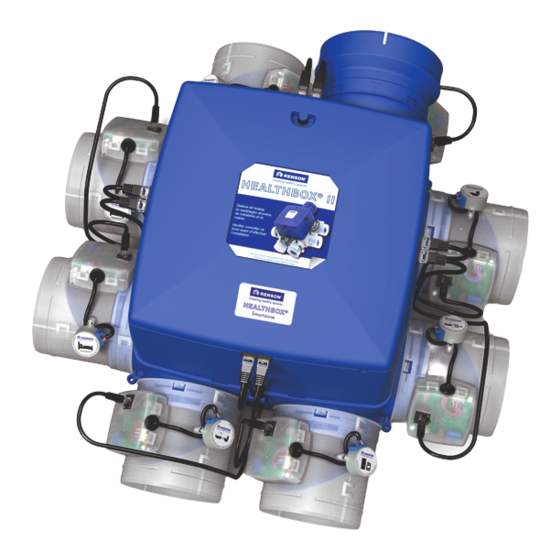
Seite 3: Professionelles Produkt
Der Privatkunde darf sein Inbetriebnahmeprotokoll nicht selbst ausfüllen! Wenn die Healthbox ® als bloßer Kauf an den Endkunden ohne gründliche Beratung des Privatkunden und damit ohne fachliche Einjustierung verkauft wird, kann Renson Ventilation nv nicht für falsch einjustierte ® Systeme oder falsch angeschlossene Leitungen haftbar gemacht werden. Damit kann auf sämtliche... -
Seite 4: Elektrischer Schaltplan
2 • Elektrischer Schaltplan 2.1 • Healthbox II (Compact) ® ➊ ➋ Aufstellungsraum Healthbox ® Anschlusskabel XVK4 Netzkabel Min. 10x0.34 mm 3G1.5 mm ➊ ➋ Max. 10x0.8 mm Max. 30 m Max. 30 m ACHTUNG: zum Beispiel Vorverkabeltes Rohr LIYY, SVV 3G2.5 mm Die Installation und der elektrische 3G1.5 mm... - Seite 5 2.2 • Healthbox II (Compact) TouchDisplay ® ➊ ➊ ACHTUNG: Die Installation und der elektrische Anschluss der verschiedenen Bauteile dürfen ausschließlich durch autorisiertes Personal und gemäß vorgeschriebener Sicherheitsmaßnahmen erfolgen. Min. 2 x 0,75 mm = 1 A Rückansicht ➊ 50Hz 230V AC ±10% Spannungsversorgung...
-
Seite 6: Dipswitch-Einstellungen
3 • Dipswitch Einstellungen Die Healthbox II hat eine feste Anzahl Regelventile, die nachfolgend beschrieben sind. ® Diese sind allesamt auf die korrekte Mindestleistung und auf die korrekte Regelwerte (RW) vorjustiert. Wenn die Situation dies erfordert, darf ausschließlich der Installateur die Leistung oder Regelwerte ändern (siehe nachfolgend in dieser Rubrik). - Seite 7 1 2 3 4 5 6 7 8 1 2 3 4 5 6 7 8 Smartzone Smartzones Anlage Schlafzimmer - 30 m Anlage Schlafzimmern - 105 m RW: CO = 900ppm RW: CO = 800ppm * Nur in Kombination mit dem TouchDisplay 1 2 3 4 5 6 7 8 Anlage kochen 75 m...
-
Seite 8: Regelventil Anlage Kochen
3 • Dipswitch-Einstellungen 3.1 • Einstellen der Regelwerte (in Verantwortung des Installateurs*) Regelventil mit Sensor Regelventil mit CO Sensor dynamische VOC und/ Damit wird das CO Threshold-Niveau bestimmt oder H 1 2 3 4 5 6 7 8 1 2 3 4 5 6 7 8 1 2 3 4 5 6 7 8... -
Seite 9: Einstellung Der Leistung
3.2 • Einstellung der Leistung (Änderung in Verantwortung des Installateurs*) 1 2 3 4 5 6 7 8 1 2 3 4 5 6 7 8 1 2 3 4 5 6 7 8 1 2 3 4 5 6 7 8 1 2 3 4 5 6 7 8 15 m... -
Seite 10: Verfahren Zum Einjustieren
4 • Verfahren zum Einjustieren • Bei der Einjustierung ist es wichtig 1. Alle Zuluftöffnungen (Lüftungsgitter, Fensterlüfter) sind vollständig zu öffnen 2. Alle Innentüren sind vollständig zu öffnen 3. Die Türspalte an den Innentüren sind nach DIN 1946-6 ausreichend zu dimensionieren oder es sind passende Überströmöffnungen an den Innentüren vorzusehen 4. -
Seite 11: Einjustieren Über Den Schalter
4.1 • Einjustieren über den Schalter • Folgen Sie zuerst die Schritte wie in Rubrik 4 beschrieben. ➀ • LEDs ➀ und ➃ des Schalters werden dauerhaft blinken. • Verfahren zum Einjustieren: ➃ Drücken Sie beide Taster ➀ und ➃ gleichzeitig längere Zeit (> 5 sec.). •... -
Seite 12: Einjustieren Über Die Hauptplatine
4.2 • Einjustieren über die Hauptplatine • Folgen Sie zuerst die Schritte wie in Rubrik 4 beschrieben. • Die Status-LED wird rot blinken. • Verfahren zum Justieren: INIT-Taster länger gedrückt halten (> 5 sec.), bis die Status-LED dauerhaft rot leuchtet. •... -
Seite 13: Einjustierung
4.3 • Einjustierung über TouchDisplay • Folgen Sie zuerst die Schritte wie in Rubrik 4 beschrieben. • Beim Start erscheint das Fenster, auf dem Tag und Tageszeit eingestellt werden müssen: - Die Tagesangabe leuchtet auf. Mit ▲ oder ▼ kann der gewünschte Tag eingestellt werden. - Seite 14 • Nach einer erfolgreichen Verlinkung erscheint das Fenster “Fan Not Ready”: (dies dauert ±1 Minute). • Wenn der Link nicht zu Stande gekommen ist, erscheint folgendes Fenster: Wiederholen Sie das Verfahren. • Wenn die Healthbox II bereit ist zur Einjustierung, erscheint das Kalibrierungsfenster. ®...
-
Seite 15: Sicherheitsvorschriften
• Warten Sie immer mindestens 30 Sekunden bevor Sie erneut Spannung anschließen. Sicherheitsanweisungen: A. Die gesamte Verkabelung ist von einer autorisierten Fachkraft durchzuführen. B. Achten Sie darauf, dass die Stromversorgung 230V, 1 Phase, 50Hz entspricht ! C. Die Lüftereinheit darf nur mit passender RENSON Zubehörteilen, Leitungen und Schaltereinheit ® verwendet werden. -
Seite 16: Allgemeine Sicherheitsvorschriften
Lösungsmittel, Mängel infolge unsachgemäßer oder unnormaler Nutzung, kleine Verarbeitungsmängel, die die Tauglichkeit nicht beeinträchtigen, Schäden infolge von Farbe, Schäden infolge von Durchbohren, Mängel infolge unsachgemäßer Reparaturen durch Dritte, Spannungsspitzen des Stromnetzes, Blitzeinschlag, Gewalt, Krieg. Für die detaillierten Garantiebedingungen konsultieren Sie bitte unsere Website www.renson.eu. - Seite 32 RENSON reserves the right to make technical changes to the ® products shown. The most recent versions of our brochures can be downloaded from www.renson.eu VE N TI L AT I ON S UN PROTE C T ION ® NV RENSON Ventilation SA •...