Seltron CMP25-2 Bedienungsanleitung
Witterungsgeführte heizungsregler des mischerheizkreises

Verwandte Anleitungen für Seltron CMP25-2


Inhaltszusammenfassung für Seltron CMP25-2
- Seite 1 Weather compensated controller for mixing heating circuits Witterungsgeführte Heizungsregler des Mischerheizkreises Regolatore climatico per circuiti di riscaldamento miscelati Régulateur de vanne mélangeuse pour circuits de chauffage CMP25-2...
-
Seite 53: Einleitung
Die Regulierung erfolgt durch den Mischerheizkreis. Die Vorprogrammierung der Raumheizung erfolgt mittels einer eingebauten digitalen Mehrkanaluhr. Die Regler CMP25-2 können ins Netz verbunden werden und fungieren als ein einheitliches Regelungssystem mit mehreren Heizkreisen. Für die erste Inbetriebnahme des Reglers, siehe REGLEREINSTELLUNG BEI... - Seite 54 INHALT BEDIENUNGS- UND EINSTELLUNGSANLEITUNGEN BESCHREIBUNG DES REGLERS ......................56 Aussehen des Reglers CMP25-2 ......................56 Betriebsartsignalisierung ......................... 56 REGLEREINSTELLUNG BEI DER ERSTEN INBETRIEBNAHME ..........57 Verlauf der Einstellung ..........................57 GRAPHISCHER LCD DISPLAY ......................59 Aussehen des Displays ..........................59 Beschreibung der Symbole am Display .....................
- Seite 55 INHALT MONTAGEANLEITUNGEN MONTAGE DES REGLERS ........................89 Montage auf das Mischventil ........................89 Elektrisches Anschluss des Reglers ...................... 91 Anschlusse für die Stromversorgung ..................91 Anschlusse für Fühler und BUS Verbindungen ............... 91 Anschluss der Raumeinheit DD2+ ......................92 Anschluss des Raumfühlers ........................93 Montagebeschreibung und Temperaturfühlerbezeichnung ............
-
Seite 56: Bedienungs- Und Einstellungsanleitungen
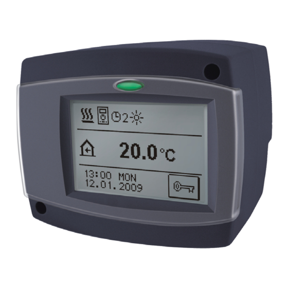
BESCHREIBUNG DES REGLERS AUSSEHEN DES REGLERS CMP25-2 1. Graphischer Touch-Screen. 2. Taste - Esc. 3. Schutzabdeckung. BETRIEBSARTSIGNALISIERUNG LED Licht leuchtet: Grün - das Mischventil schließt Rot - das Mischventil öffnet 56 | Bedienungs- und Einstellungsanleitungen... -
Seite 57: Reglereinstellung Bei Der Ersten Inbetriebnahme
REGLEREINSTELLUNG BEI DER ERSTEN INBETRIEBNAHME Die Heizungsregler CMP25-2 beinhalten eine innovative Lösung “EASY START”, die eine einfache Einstellung mit Hilfe eines Assistenten ermöglicht. VERLAUF DER EINSTELLUNG Bei der Ersteinschaltung des Reglers ans Netz oder nach dem Reset des Reglers wird, nach der Angabe der Programmversion der Assistent zum Einstellen des Reglers aktiviert. -
Seite 58: Schritt - Sprachenauswahl
REGLEREINSTELLUNG BEI DER ERSTEN INBETRIEBNAHME 3. SCHRITT - SPRACHENAUSWAHL Mit dem Drücken auf das entsprechende Symbol wählt man die Soll-Sprache aus. Nachdem Sie die Sprache angewählt haben, bestätigen Sie die mit drücken der Taste 4. SCHRITT - HYDRAULIKSCHEMAAUSWAHL ODER Das Hydraulikschema des Reglerbetriebs auswählen. Die Wahl mit Drücken der Taste bestätigen. -
Seite 59: Graphischer Lcd Display
GRAPHISCHER LCD DISPLAY Das graphische Display hat ein berührungsempfindliches Display, welches neben der Daten über die Leistung auch zur Einstellung der Reglerfunktion dient. Am LCD Display können Informationen über die Leistung des Reglers durchgeblättert werden und die Betriebseinstellungen geändert werden. AUSSEHEN DES DISPLAYS Betriebssignalisierung der Pumpen... -
Seite 60: Symbole Zur Darstellung Der Benutzerfunktionen
GRAPHISCHER LCD DISPLAY SYMBOLE ZUR DARSTELLUNG DER BENUTZERFUNKTIONEN Symbol Beschreibung Party Urlaub - aktueller Tag Estrichtrocknung - dauer Sommerbetrieb Konstantere Vorlauftemperaturbetrieb Fernschaltung Boost Heizung SYMBOLE ZUR DARSTELLUNG DER TEMPERATUR UND ANDERE DATEN Symbol Beschreibung Die Ist-Temperatur Die ausgerechnete oder Soll-Temperatur Raumtemperatur Außentemperatur Vorlauftemperatur... -
Seite 61: Symbole Zur Darstellung Der Schutzfunktionen
GRAPHISCHER LCD DISPLAY Symbol Beschreibung Umwälzpumpe aktiv T1, T2, T3, T4 Temperatur des Fühlers T1, T2, T3 oder T4. Temperatur der Raumeinheit DD2+. Außentemperatur, die durch der Bus-Verbindung erhalten wurde. Kesseltemperatur, die durch der Bus-Verbindung erhalten wurde. SYMBOLE ZUR DARSTELLUNG DER SCHÜTZFUNKTIONEN Symbol Beschreibung Kesselüberhitzungsschutz... -
Seite 62: Warnsymbole
GRAPHISCHER LCD DISPLAY WARNSYMBOLE Symbol Beschreibung Meldung Im Falle einer Überschreitung der maximalen Temperatur oder des Einschaltens der Schutzfunktion blinkt auf der Anzeige ein entsprechendes Symbol. Wenn die maximale Temperatur nicht mehr überschritten ist oder sich die Schutzfunktion wieder abgeschaltet hat, wird auf der Anzeige ein entsprechendes Symbol angezeigt. -
Seite 63: Display Ent- Und Zusperren
GRAPHISCHER LCD DISPLAY DISPLAY ENT- UND ZUSPERREN Wenn man die Reglereinstellungen verändern möchte oder die Betriebsdaten d urchblättern möchte, muss das Display erst mit dem Drücken auf die Taste entsperrt werden. Das Display wird 15 min nach dem letzten Drücken einer beliebigen Taste automatisch zugesperrt. -
Seite 64: Offnen Des Menüs Und Der Navigation
ÖFFNEN DES MENÜS UND DER NAVIGATION Das Display wird mit dem Drücken der Taste entspärrt. Ins Einstellmenü gelangt man mit Drücken der Taste T1= 21°C T3= 45°C T2= 5°C T4= 65°C Innerhalb des Menüs bewegt man sich durch Drücken der Ikonen, die am Display angezeigt werden. -
Seite 65: Menüstruktur Und Menübeschreibung
MENÜSTRUKTUR UND MENÜBESCHREIBUNG TEMPERATUREINSTELLUNGEN Tagestemperatur Nachttemperatur BENUTZERFUNKTIONEN Party Urlaub Funktion abschalten BETRIEBSART Automatikbetrieb Tagestemperaturbetrieb Nachttemperaturbetrieb Regler abschalten Heizung / Kühlung Umschaltung Manueller Betrieb Bedienungs- und Einstellungsanleitungen | 65... - Seite 66 MENÜSTRUKTUR UND MENÜBESCHREIBUNG ZEITPROGRAMME Zeitprogramm 1 Zeitprogramm 2 Zeitprogramm 3 Zeitprogramm 4 GRUNDEINSTELLUNGEN Sprachenauswahl Zeit und Datum DISPLAY EINSTELLUNG Dauer der aktiven Displaybeleuchtung und Menu Autoausgang Intensität der aktive Displaybeleuchtung Intensität der inaktiven Displaybeleuchtung Kontrast DATEN KONTROLLE Graphische Darstellungen der gemessenen Temperaturen für die vergangene Woche Graphische Darstellungen der Temperaturen des aktuellen Tages...
- Seite 67 MENÜSTRUKTUR UND MENÜBESCHREIBUNG GRUNDPARAMETER Grundeinstellungen Mischerheizkreiseinstellungen Wärmequelleneinstellungen WARTUNGSPARAMETER Grundeinstellungen Mischerheizkreiseinstellungen Wärmequelleneinstellungen DIE PARAMETER DER ESTRICH TROCKNUNG WERKSEINSTELLUNGEN Reset der Regler Parameter Reset der Zeitprogramme Reset des Reglers und erneuter Start der Ersteinstellung Benutzereinstellungen speichern Benutzereinstellungen laden Bedienungs- und Einstellungsanleitungen | 67...
-
Seite 68: Temperatureinstellung
TEMPERATUREINSTELLUNG TAGESTEMPERATUR Mit den Tasten wird der Soll-Wert der Temperatur eingestellt. Die Einstellung bestätigt man mit der Taste und blättert auf das vorige Display zurück. NACHTTEMPERATUR Mit den Tasten wird der Soll-Wert der Temperatur eingestellt. Die Einstellung bestätigt man mit der Taste und blättert auf das vorige Display zurück. - Seite 69 BENUTZERFUNKTIONEN Temperatureinstellung Zeit der Abschaltung Mit drücken der ECO Taste schalten wir die Raumheizung auf sparsame Temperatur. Zur Einstellung der Eco-Funktion, drücken sie noch einmal das Eco-Symbol. Mit den Tasten wählt man die Soll-Temperatur und die Zeit der Abschaltung der Funktion aus. Temperatureinstellung Zeit der Abschaltung URLAUB...
-
Seite 70: Betriebsartenwahl
BETRIEBSARTENWAHL Man kann zwischen sechs Arten des Reglerbetriebs auswählen. Betrieb nach Zeitprogramm Der Betrieb erfolgt nach Ablauf der gewählten Zeit-Programm. Wenn die Raumeinheit angeschlossen ist, wird das Symbol angezeigt (Die Zahl sagt uns, welche Raumeinheit Auswirkungen auf den Heizkreis hat). Wenn der Regler ohne die Raumeinheit funktioniert zeigt er die Ikone Betrieb nach Tagestemperatur Der Regler arbeitet in Hinsicht auf die Einstellung der Soll-Tagestemperatur. -
Seite 71: Zeitprogramme
ZEITPROGRAMME ZEITPROGRAMM AUSWÄHLEN Zur Auswahl stehen Ihnen Vier, von einander unabhängige Zeitprogramme zur Verfügung. Nachdem man das gewünschte Zeitprogramm angewählt hat, bestätigt man es mit der Taste und blättert auf das vorige Display zurück. Änderungen im Zeitprogramm Um das Zeitprogramm zu ändern, muss man die Ikone zwei Mal drücken. Eine neue Anzeige erscheint: Der jeweilige Tag und die... -
Seite 72: Zeitprogramm Einstellen
ZEITPROGRAMME ZEITPROGRAMM EINSTELLEN Die Bedeutung der Displaytaste ist wie folgt: Freie Bewegung entlang der Zeitlinie Darstellung des Heizintervalls auf der Bewegung Nachttemperatur / Tagesintervall löschen nach links Bewegung Darstellung des Heizintervalls auf der nach rechts Tagestemperatur / Nachtintervall löschen Auf das vorige Display zurückblättern und die Änderungen im Zeitprogramm speichern Mit Hilfe der genannten Tasten wird der Verlauf des Zeitprogramms für den jeweiligen Tag dargestellt. -
Seite 73: Werkseinstellungen Der Zeitprogramme
ZEITPROGRAMME WERKSEINSTELLUNGEN DER ZEITPROGRAMME Raumheizung in Betrieb MO.-FR. 06:00 - 22:00 SA.-SO. 07:00 - 22:00 Raumheizung in Betrieb 05:00 - 7:30 MO.-FR. 13:30 - 22:00 SA.-SO. 07:00 - 22:00 Raumheizung in Betrieb 06:00 - 08:30 MO.-FR. 11:00 - 13:30 16:00 - 22:00 SA.-SO. -
Seite 74: Grundeinstellungen
GRUNDEINSTELLUNGEN Das Menü dient zur Einstellung der Sprache, der Zeit und des Datums sowie der Ein- stellung des Displays. SPRACHE Die Soll- Sprache wird wie folgt eingestellt: Mit den Tasten oder bewegt man sich durch die Displays mit den Sprachen. Mit dem Drücken der Ikone wählt man die Soll-Sprache aus. -
Seite 75: Daten Kontrolle
GRUNDEINSTELLUNGEN DATEN KONTROLLE Im Menü befinden sich Ikonen, die Ihnen einen Zugang zu den folgenden Betriebsarten des Reglers ermöglichen: GRAPHISCHE DARSTELLUNGEN DER GEMESSENEN TEMPERATUREN FÜR DIE VERGANGENE WOCHE - Detaillierte grafische Übersicht von Tages Fühlertemperaturen gemessen in der vergangenen Woche. GRAPHISCHE DARSTELLUNGEN DER TEMPERATUREN DES AKTUELLEN TAGES - Detaillierte grafische Übersicht der einzelnen Temperaturen in einen Tag für alle Fühler. - Seite 76 REGLERPARAMETER BASIC PARAMETERS The basic parameters are listed in groups P1 - basic settings, P2 - settings for heating circuit, P3 - settings for heat sources. Content of basic parameters is displayed as follows: Parameterbezeichnung Parameterwert Einstellbereich Werkseinstellung des Parameters Beschreibung des Parameters Die gewünschte Parameteränderung wird am unteren Beispiel am Parameter P1.1...
- Seite 77 REGLERPARAMETER GRUNDEINSTELLUNGEN: Para- Parameterbezeichnung Beschreibung des Parameters Einstellungs- Über- meter bereich nomme- ner Wert P1.1 AUTOMATISCHER Der Regler schaltet Heizung 0- NEIN SOMMER/WINTER automatisch aus, wenn die 1- JA UMSCHALTUNG durchschnittliche Eintagestempe- ratur höher ist als die eingestellte Umschalttemperatur. P1.2 DURCHSCHNITTS- Einstellung der durchschnittlichen 10 ÷...
-
Seite 78: Mischerheizkreiseinstellungen
REGLERPARAMETER MISCHERHEIZKREISEINSTELLUNGEN: Para- Parameterbez- Beschreibung des Parameters Einstel- Übernomme- meter eichnung lungs- ner Wert bereich P2.1 HEIZKURVES- Die Steilheit der heizkurve bestimmt, 0,2 ÷ 2,2 0,7 - TEILHEIT wie hoch an Hand der Fußboden Außentemperatur die Temperatur 1,0 - der Heizkörper sein soll. Der Wert der Radiatoren Heizkurvensteilheit ist vor allem von der Art des Heizsystems abhängig... -
Seite 79: Heizkurve
HEIZKURVE Die Steilheit der heizkurve bestimmt, wie hoch an Hand der Außentemperatur die Temperatur der Heizkörper sein soll. Der Wert der Heizkurvensteilheit ist vor allem von der Art des Heizsystems abhängig (Fußboden-, Wand- , Radiator-, und Konvektorheizung) und von der Wärmedehnung des Gebäudes. Bestimmung der Heizkurvensteilheit Wenn genügend Daten zur Verfügung stehen, wird die Heizkurvensteilheit rechnerisch bestimmt, am sonsten auf der Grundlage der Bemessungen des Heizsystems und der... - Seite 80 HEIZKURVE HEIZKURVENDIAGRAM S=2,2 S=2,0 S=1,8 Tvmax S=1,6 S=1,4 S=1,2 S=1,0 S=0,8 Tkmin S=0,6 Tvmin S=0,4 S=0,2 Außentemperatur [°C] 80 | Wartungsanleitungen...
-
Seite 81: Wartungsparameter
WARTUNGSPARAMETER In Wartungsparameter befinden sich in den Gruppen P1 - Grundeinstellungen, P2 - Mischerheizkreiseinstellungen, P3 - Wärmequelleneinstellungen. Der Inhalt der Wartungsparameter wird wie folgt ausgeschrieben: - Verriegelte Parameter Parameterbezeichnung Parameterwert Einstellbereich Werkseinstellung des Parameters Beschreibung des Parameters Navigationstasten Die gewünschten Parametern werden Geändert in der gleichen Weise wie die Grundeinstellung (P). - Seite 82 WARTUNGSPARAMETER GRUNDEINSTELLUNGEN: Para- Parameter- Beschreibung des Parameters Einstellungs- Übernom- meter bezeichnung bereich mener Wert S1.1 HYDRAULIK- Auswahl des gewünschten 360 ÷ 360b SCHEMA Hydraulikschemas. S1.2 ENTSPERR- Die Einstellung ermöglicht eine 0000 ÷ 9999 0001 KODE FÜR Veränderung des Kodes, not- AUFSCHLIES- wendig für die Aufschließung der SUNG DER...
- Seite 83 WARTUNGSPARAMETER Para- Parameter- Beschreibung des Parameters Einstellungs- Übernom- meter bezeichnung bereich mener Wert S1.8 FERNSCHAL- Hier wählt man an, ob bei der 1- LOKAL TUNG BEI Fernschaltung nur die lokale 2- MIT BUS BUS-VERBIN- Fernschaltung berücksichtigt DUNGEN wird oder ob auch die Fernschal- tung des Hauptreglers berück- sichtigt wird.
- Seite 84 WARTUNGSPARAMETER MISCHERHEIZKREISEINSTELLUNGEN: Para- Parameter- Beschreibung des Parameters Einstellungs- Über- meter bezeichnung bereich nommen- er Wert S2.1 AUSWIRKUNG Einstellen der Auswirkung der 0,0 ÷ 3,0 DER RAUM- Raumtemperaturabweichung auf die TEMPERATUR errechnete Vorlauftemperatur. Niedrige Werte bedeuten eine Kleinere Auswirkungen und höhere Werte stärkere Auswirkungen auf den Regler.
- Seite 85 WARTUNGSPARAMETER Para- Parameter- Beschreibung des Parameters Einstellungs- Über- meter bezeichnung bereich nommen- er Wert S2.5 MINIMALE Das Einstellen der Begrenzung der 10 ÷ 90 °C VORLAUF- minimalen Vorlauftemperatur. TEMPERATUR S2.6 MAXIMALE Das Einstellen der Begrenzung der 20 ÷ 150 °C VORLAUF- maximalen Vorlauftemperatur.
-
Seite 86: Wärmequelleneinstellungen
WARTUNGSPARAMETER Para- Parameter- Beschreibung des Parameters Einstellungs- Über- meter bezeichnung bereich nommen- er Wert S2.13 DIFFERENZ- Das Einstellen der maximalen 3 ÷ 30 K BESCHRÄNK. erlaubten Differenz zwischen Vorlauf ZWISCHEN und Rücklaufleitung. Auf diese Weise VORLAUF wird die maximale Leistung des UND RÜCK- Heizkreises begrenzt. -
Seite 87: Die Parameter Der Estrichtrocknung
WARTUNGSPARAMETER DIE PARAMETER DER ESTRICHTROCKNUNG In der F1-Gruppe, sind die Parameter zur Einstellung der Estrichtrocknung. Das Verfahren zur Einstellung der Parameter, ist der gleiche wie für die Wartungsparameter (sehe Seite 76). TROCKNEN DES ESTRICHS: Parameter Parameterbezeichnung Einstel- Übernom- lungs-bereich mener Wert 0- NEIN F1.1 AKTIVIEREN DER ESTRICHTROCKNUNG... -
Seite 88: Trocknen Des Estrichs - Werkseinstellungen
WARTUNGSPARAMETER Trocknen des Estrichs - Werkseinstellungen: F1.2 F1.5 F1.8 F1.11 °C Nr. der Št. dni Tage WERKSEINSTELLUNGEN Im Menü befinden sich Softwarewerkzeuge, für leichteres Einstellen des Reglers. Ihnen stehen fünf Befehle zur Verfügung: RESET DER REGLER PARAMETER Stellt alle Parametereinstellungen P1, P2, P3, S1 (außer S1.1), S2, S3 und F auf Werkseinstellungen zurück. -
Seite 89: Montage Des Reglers
öffnen. MONTAGE AUF DAS MISCHERVENTIL Die Montageart, die unten dargestellt wird, gilt für Mischerventile der folgenden Hersteller: Esbe, Seltron, Somatherm, Acaso, Ivar, Wip, Paw, BRV, Imit, Hora, Barberi, Olymp, Hoval. 1a 1a Beispiel der Montage auf das Dreiwegventil. - Seite 90 MONTAGE DES REGLERS Beispiel: Montagebeispiel Beispiel: Montagebeispiel auf das Dreiwegventil. auf das Vierwegventil. 90 | Montageanleitungen...
-
Seite 91: Elektrisches Anschluss Des Reglers
ELEKTRISCHES ANSCHLUSS DES REGLERS Die Zeichnungen und die Texte in der vorliegenden Anleitung haben lediglich Beispielcharakter, für die der Herausgeber keine Verantwortung übernimmt. Benutzen Sie in diesen Anleitungen vermittelte Inhalte, geschieht dies auf das eigene Risiko und Sie tragen die Verantwortung. Der Herausgeber haftet nicht für unsachgemäße, unvollständige und falsche Angaben und die daraus resultierende Schäden werden grundsätzlich aus- geschlossen. -
Seite 92: Anschluss Der Raumeinheit Dd2
ANSCHLUSS DER RAUMEINHEIT DD2 + Mit der Raumeinheit messen wir die Raumtemperatur, stellen die Tag und Nacht Temperatur ein und wählen die Betriebsart aus. Auf ein Steuergerät können bis maximal zwei Raumeinheiten angeschlossen werden. Bevor Sie die Raumeinheit anschließen, ist eine Einstellung der Kodier Schalter auf der Rückseite der Raumeinheit notwendig. -
Seite 93: Anschluss Des Raumfühlers
ANSCHLUSS DES RAUMFÜHLERS Der Raumfühler wird für das Messen der Raumtemperatur verwendet genau wie der Fühler der digitalen Raumeinheit DD2+. Dies verbessert die Regelung der gewünschten Raumtemperatur. Für das Funktionieren des Reglers ist der Raumfühler nicht notwendig. Beim Anschluss des Raumfühlers müssen Sie den Parameter S1.6=0 einstellen. -
Seite 94: Elektrisches Anschluss Des Reglers
ELEKTRISCHES ANSCHLUSS DES REGLERS Raumfühler oder Raumeinheit Die Raumeinheit an die Innenwand des Wohnzimmers befestigen. Dazu suchen Sie sich die schattige Wand aus, die von jeglicher Wärmequelle oder Durchzug entfernt ist. Zuerst den Schutzdeckel abnehmen, dann den Sockel an die vorgesehene Stelle, ca. 1,5 Meter über Fußboden, montieren. -
Seite 95: Betriebsbeschreibung Bei Fühlerstörung
BETRIEBSBESCHREIBUNG BEI FÜHLERSTÖRUNG Wenn einer der Temperaturfühler ausfällt, dann justiert sich der Regler auf den verwendbarsten Betriebsmodus: Außentemperaturfühler ist Außerbetrieb oder Defekt Der Regler funktioniert in dem Fall als P-Regler in Hinsicht auf die Raumtemperaturabweichung. Wenn der Raumtemperaturfühler auch beschädigt ist, wird die Vorlauftemperatur mit konstanten Temperatur reguliert, die bei: - Radiatorheizung 25 °C mehr als eingestellte Tages bzw. -
Seite 96: Systemerweiterung Auf Mehrere Heizkreise
Wärmequelle BUS connection of controllers CMP25-2 and WDC10B, WDC10 or WDC20: Mit der Bus-Verbindung können Sie eine beliebige Anzahl von WDC und CMP25-2 Reglern miteinander verbinden. Der Hauptregler WDC steuert die Wärmequellen, wäh- rend die anderen nur die Heizkreise steuern. -
Seite 97: Bus-Verbindung Zwischen Cmp25-2 Und D10, D20 Reglern
MEHRERE HEIZKREISE BUS-Verbindung zwischen CMP25-2 und D10, D20 Reglern: Mit der Bus-Verbindung können Sie eine beliebige Anzahl von D10, D20 und CMP25-2 Reglern miteinander verbinden. Der Hauptregler D10 oder D20 steuert die Wärmequellen, während die anderen nur die Heizkreise steuern. -
Seite 98: Hydraulikschemen
HYDRAULIKSCHEMEN WICHTIG ACHTUNG: Die Installationsschemas verweisen auf den Betriebsprinzip und verfü-gen nicht über alle Hilfs- oder Sicherheitselemente. Bei der Montage die gültigen vorschriften beachten! Optional Fühler. Für das Funktionieren der Regelung nicht erforderlich. Anschließung eines Raumfühlers oder einer Raumeinheit ist für den Betrieb des Reglers nicht erforderlich. - Seite 99 HYDRAULIKSCHEMEN SCHEMA 360B MISCHERHEIZKREIS, (ERWEITERUNGSREGLER) BUS Verbindung der Regler ist auf den Seiten 96 und 97 beschrieben. Hydraulikschemen | 99...
-
Seite 100: Technische Daten
TECHNISCHE DATEN Allgemeine technische Daten Stromversorgung ......................230 V ~ , 50 Hz, Leistungsaufnahme ........................Max. 4 VA Pumpenausgang ......................230 V ~ / 4 (2) A Reglergehäuse ......................ABS -Thermoplast Dimensionen (B x H x T): ..................84 × 105 × 100 mm Gewicht .......................... -
Seite 101: Entsorgung Von Gebrauchten Elektrischen Und Elektronischen Geräten
Entsorgungsbetrieben, oder dem Geschäft, in dem Sie das Produkt gekauft haben. CE - KONFORMITÄTSERKLÄRUNG Der Kompaktregler PROMATIC CMP25-2 entsprecht folgenden Richtlinien und Normen: - EU-Niederspannungsrichtlinie (LVD) 2014/35/EC, - EU-Richtlinie für Elektromagnetische Verträglichkeit (EMC) 2014/30/EEC, - EU-Richtlinie Elektro- und Elektronikschrott, Stoffverbote 2011/65/EC (Rohs II) . - Seite 204 J5060439 CMP25-2 v3.2r2 ©2020 We reserve the rights for changes and improvements. Wir behalten uns das Recht auf Veränderungen und Verbesserungen vor. Ci si riserva la facoltà di apportare modifiche e migliorie senza preavviso. Nous réservons les droits pour des changements et des améliorations.