Anmelden
Hochladen
Anleitungen
Marken
flamco Anleitungen
Controller
meibes Logotherm MeiFlow M LFC
flamco meibes Logotherm MeiFlow M LFC Handbücher
Anleitungen und Benutzerhandbücher für flamco meibes Logotherm MeiFlow M LFC. Wir haben
1
flamco meibes Logotherm MeiFlow M LFC Anleitung zum kostenlosen PDF-Download zur Verfügung: Montage- Und Serviceanleitung
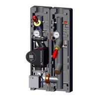
flamco meibes Logotherm MeiFlow M LFC Montage- Und Serviceanleitung (132 Seiten)
Marke:
flamco
| Kategorie:
Controller
| Dateigröße: 9.6 MB
Inhaltsverzeichnis
Deutsch
2
Inhaltsverzeichnis
2
1 Sicherheitshinweise
3
Vorschriften/Richtlinien
3
Bestimmungsgemäße Verwendung
4
Erstinbetriebnahme
4
Arbeiten an der Anlage
4
Haftung
4
2 Geräte und Funktionsbeschreibung
5
Funktionsbeschreibung
5
Temperaturdifferenzabhängige Pumpenleistungsberechnung
5
3 Aufbau der Pumpengruppen
6
Schematische Darstellung
6
Abmessungen und Komponenten V-PG, DN 32
7
Abmessungen und Komponenten FL-PG, DN 40, 50 und 65
8
4 Optionales Zubehör
9
Wandhalterungen für Pumpengruppen DN 32 - 65
9
Meitronic LFC - Elektrische Verschaltung und Verkabelungspläne
10
Klemmplan: Allgemeine Darstellung
11
Klemmplan für Ungemischte Pumpengruppen
12
Klemmplan für Gemischte Pumpengruppen, Stellmotor mit 230 V
13
Klemmplan für Gemischte Pumpengruppen, Stellmotor mit 24 V
14
English
15
1 Safety Instructions
16
Regulations/Guidelines
16
Intended Use
17
Commissioning
17
When Working on the System
17
Liability
17
2 Devices and Functional Description
18
Functional Description
18
Differential Temperature Dependent Calculation of Pump Output
18
3 Set-Up of the Pump Groups
19
Visual Representation
19
Dimensions and Components V-PG, DN 32
20
Dimensions and Components FL-PG, DN 40, 50 and 65
21
4 Optional Accessories
22
Wall Brackets for Pump Groups DN 32 - 65
22
Meitronic LFC - Electrical Switching and Cabling Plans
23
Block Plan: General Representation
24
Block Plan for Unmixed Pump Groups
25
Block Plan for Mixed Pump Groups, Servomotor at 230 V
26
Block Plan for Mixed Pump Groups, Servomotor at 24 V
27
Français
28
1 Consignes de Sécurité
29
Réglementations/Directives
29
Utilisation Conforme
30
Première Mise en Service
30
Interventions Sur L'installation
30
Responsabilité
30
2 Appareils et Description du Fonctionnement
31
Description du Fonctionnement
31
Calcul de la Puissance de Pompage en Fonction de la Différence de Température
31
3 Montage des Groupes de Pompe
32
Représentation Schématique
32
Mesures et Composants V-PG, DN 32
33
Mesures et Composants FL-PG, DN 40, 50 et 65
34
4 Accessoires en Option
35
Supports Muraux pour Groupes de Pompe DN 32 - 65
35
Meitronic LFC - Câblage Électrique et Plans de Câblage
36
Schéma des Bornes : Représentation Générale
37
Schéma des Bornes pour Groupes de Pompe Non-Mélangés
38
Schéma des Bornes pour Groupes de Pompe Mélangés, Servomoteurs Avec du 230 V
39
Schéma des Bornes pour Groupes de Pompe Mélangés, Servomoteurs Avec du
40
Dutch
41
1 Veiligheidsaanwijzingen
42
Voorschriften/Richtlijnen
42
Doelmatig Gebruik
43
Eerste Inbedrijfname
43
Werken Aan de Installatie
43
Aansprakelijkheid
43
2 Apparaten en Functiebeschrijving
44
Functiebeschrijving
44
Berekening Van de Pompcapaciteit Afhankelijk Van Het Temperatuurverschil
44
3 Opbouw Van de Pompgroepen
45
Schematische Weergave
45
Afmetingen en Componenten V-PG, DN 32
46
Afmetingen en Componenten FL-PG, DN 40, 50 en 65
47
4 Optionele Accessoires
48
Muurbeugels Voor Pompgroepen DN 32 - 65
48
Meitronic LFC - Elektrische Bedradings- en Bekabelingsplannen
49
Klemplan: Algemene Weergave
50
Klemplan Voor Ongemengde Pompgroepen
51
Klemplan Voor Gemengde Pompgroepen, Stelmotor Met 230 V
52
Klemplan Voor Gemengde Pompgroepen, Stelmotor Met 24 V
53
Čeština
54
1 Bezpečnostní Upozornění
55
Předpisy/Směrnice
55
PoužíVání Ke Stanovenému Účelu
56
První Uvedení Zařízení Do Provozu
56
Práce Na Zařízení
56
Ručení
56
2 Zařízení a Popis Funkce
57
Popis Funkce
57
Výpočet Výkonu Čerpadla V Závislosti Na Rozdílu Teplot
57
3 Konstrukce Čerpadlových Skupin
58
Schematické Zobrazení
58
Rozměry a Komponenty V-PG, DN 32
59
Rozměry a Komponenty FL-PG, DN 40, 50 a 65
60
4 Volitelné Příslušenství
61
Konzole Na Stěnu Pro Čerpadlové Skupiny
61
Meitronic LFC - Elektrické Zapojení a Schémata Kabelových Rozvodů
62
Schéma Svorek: Obecné Zobrazení
63
Schéma Zapojení Pro Čerpadlové Skupiny Bez Směšování
64
Schéma Zapojení Pro Čerpadlové Skupiny Se SměšováníM, Servomotor S 230 V
65
Schéma Zapojení Pro Skupiny Čerpadel Se SměšováníM, Servomotor S 24 V
66
Polski
67
1 Instrukcja Bezpieczeństwa
68
Przepisy / Wytyczne
68
Zastosowanie Zgodne Z Przeznaczeniem
69
Pierwsze Uruchomienie
69
Prace Przy Urządzeniu
69
Odpowiedzialność
69
2 Urządzenia I Opis Funkcjonalny
70
Opis Funkcjonalny
70
Obliczanie WydajnośCI Pompy Uzależnione Od Różnicy Temperatur
70
3 Budowa Grup Pompowych
71
Schematycznie Przedstawienie
71
Wymiary I Komponenty V-PG, DN 32
72
Wymiary I Komponenty FL-PG, DN 40, 50 I 65
73
4 Wyposażenie Opcjonalne
74
Uchwyty Ścienne Dla Grup Pompowych DN 32 - 65
74
Meitronic LFC - Podłączenie Elektryczne I Schematy Elektryczne
75
Schemat Zacisków: Prezentacja Ogólna
76
Schemat Zacisków Dla Grup Pompowych Bez Mieszania
77
Schemat Zacisków Dla Grup Pompowych Z Mieszaniem, Siłownik 230V
78
Schemat Zacisków Dla Grup Pompowych Z Mieszaniem, Siłownik 24 V
79
Italiano
80
1 Avvertenze DI Sicurezza
81
Regolamenti/Direttive
81
Destinazione D'uso Prevista
82
Prima Messa in Funzione
82
Interventi Sull'impianto
82
Responsabilità
82
2 Dispositivi E Descrizione Delle Funzioni
83
Descrizione Delle Funzioni
83
Calcolo Della Potenza Della Pompa in Funzione Della Differenza DI Temperatura
83
3 Montaggio Dei Gruppi Pompa
84
Rappresentazione Schematica
84
Dimensioni E Componenti V-PG, DN 32
85
Dimensioni E Componenti FL-PG, DN 40, 50 E 65
86
4 Accessorio Opzionale
87
Supporti da Parete Per Gruppi Pompa DN 32 - 65
87
Meitronic LFC - Cablaggi Elettrici E Schemi DI Cablaggio
88
Schema Morsetti: Rappresentazione Generale
89
Schema Morsetti Per Gruppi Pompa Non Miscelati
90
Schema Dei Morsetti Per Gruppi Pompa Miscelati, Motore DI Regolazione a 230 V
91
Schema Dei Morsetti Per Gruppi Pompa Miscelati, Motore DI Regolazione a 24 V
92
Español
93
1 Indicaciones de Seguridad
94
Disposiciones/Directivas
94
Uso Adecuado
95
Primera Puesta en Marcha
95
Trabajos en la Instalación
95
Responsabilidad
95
2 Equipos y Descripción del Funcionamiento
96
Descripción del Funcionamiento
96
Cálculo de Potencia de la Bomba en Función de la Temperatura Diferencial
96
3 Estructura de Los Grupos de Bombeo
97
Representación Esquemática
97
Dimensiones y Componentes GB V, DN 32
98
Dimensiones y Componentes GB FL, DN 40, 50 y 65
99
4 Accesorios Opcionales
100
Soportes de Pared para Grupos de Bombeo DN 32 - 65
100
Meitronic LFC - Conmutación Eléctrica y Esquemas de Cableado
101
Esquema de Bornes: Representación General
102
Esquema de Bornes para Grupos de Bombeo sin Mezcla
103
Esquema de Bornes para Grupos de Bombeo, Servomotor de 230 V
104
Esquema de Bornes para Grupos de Bombeo, Servomotor de 24 V
105
Português
106
1 Indicações de Segurança
107
Regulamentos/Prescrições
107
Utilização Correta
108
Primeira Colocação Em Funcionamento
108
Trabalhos no Sistema
108
Responsabilidade
108
2 Descrição Do Aparelho E das Funções
109
Descrição das Funções
109
Cálculo da Potência da Bomba Dependente da Diferença de Temperatura
109
3 Montagem Dos Grupos de Bombas
110
Representação Esquemática
110
Dimensões E Componentes GB V, DN 32
111
Dimensões E Componentes GB FL, DN 40, 50 E 65
112
4 Acessórios Opcionais
113
Suportes de Parede para Grupos de Bombas DN 32 - 65
113
Meitronic LFC - Conexão Elétrica E Esquemas de Cablagem
114
Esquema de Terminais: Representação Geral
115
Esquema de Terminais para Grupos de Bombas Não Misturadas
116
Esquema de Terminais para Grupos de Bombas Misturadas, Servomotor Com 230 V
117
Esquema de Terminais para Grupos de Bombas Misturadas, Servomotor Com
118
Русский
119
1 Указания По Технике Безопасности
120
Предписания/Директивы
120
Использование По Назначению
121
Первичный Ввод В Эксплуатацию
121
Проведение Работ На Установке
121
Ответственность
121
2 Устройства И Описание Принципа Действия
122
Описание Принципа Действия
122
Расчет Производительности Насоса В Зависимости От Разницы Температур
122
3 Конструкция Насосных Групп
123
Схематическое Изображение
123
Габаритные Размеры И Компоненты V-PG, DN 32
124
Габаритные Размеры И Компоненты FL-PG, DN 40, 50 И 65
125
4 Дополнительные Комплектующие
126
Настенные Крепления Для Насосных Групп DN 32 - 65
126
Meitronic LFC - Электрические Соединения И Схемы Кабельной Разводки
127
Схема Клеммной Разводки: Общее Представление
128
Схема Клеммной Разводки Для Насосных Групп Без Смесителя
129
Схема Клеммной Разводки Для Насосных Групп Со Смесителем, Серводвигатель На 230 В
130
Схема Клеммной Разводки Для Насосных Групп Со Смесителем, Серводвигатель На 24 В
131
Werbung
Werbung
Verwandte Produkte
flamco meibes MeiTronic LFC
flamco meibes Logotherm LogoMatic Comfort 600+
flamco meibes MeiFlow Top S MF
flamco Meibes MeiFlow TOP S
flamco meibes Rossweiner heatplus
flamco Flexcon M-K 800
flamco MVE Serie
flamco Flexcon MPR-S 1.5
flamco Flexcon MPR-S 1.7
flamco Flamcomat MK 2000
flamco Kategorien
Steuergeräte
Armaturen
Industrielle Ausrüstung
Warmwasserspeicher
Wassersysteme
Weitere flamco Anleitungen
Anmelden
Anmelden
ODER
Mit Facebook anmelden
Mit Google anmelden
Anleitung hochladen
Von PC hochladen
Von URL hochladen