Herunterladen Inhalt Inhalt Diese Seite drucken

Stahl 9172 Betriebsanleitung
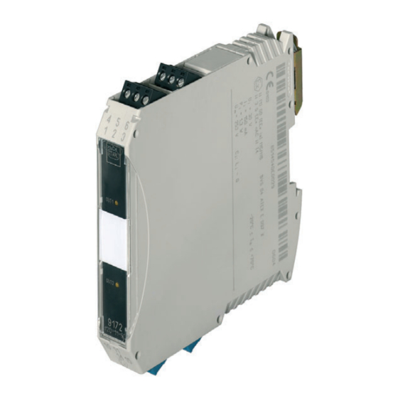
Ex i relais modul
Vorschau ausblenden Andere Handbücher für 9172:
Inhaltsverzeichnis

Werbung

Verfügbare Sprachen

Verfügbare Sprachen

Ex i Relais Modul
Reihe 9172
Betriebsanleitung
Additional languages r-stahl.com
DE
DE
DE
DE
DE
DE
DE
DE
DE
DE
DE
DE
DE
DE
DE
DE
DE
DE
DE
DE
DE
DE
DE
DE
DE
DE

Werbung

Kapitel

Inhaltsverzeichnis
loading

Inhaltszusammenfassung für Stahl 9172

  • Seite 1 Betriebsanleitung Additional languages r-stahl.com Ex i Relais Modul Reihe 9172...
  • Seite 2: Inhaltsverzeichnis

    Instandhaltung ....................11 Wartung ......................11 Reparatur ......................11 Rücksendung ....................12 Reinigung ......................12 Entsorgung ......................12 Zubehör und Ersatzteile ...................12 Anhang A ......................13 14.1 Technische Daten .....................13 Anhang B ......................16 15.1 Geräteaufbau ....................16 15.2 Maßangaben / Befestigungsmaße ..............16 Ex i Relais Modul Reihe 9172...
  • Seite 3: Allgemeine Angaben

     Betriebsanleitung während der Lebensdauer des Geräts aufbewahren.  Betriebsanleitung dem Bedien- und Wartungspersonal jederzeit zugänglich machen.  Betriebsanleitung an jeden folgenden Besitzer oder Benutzer des Geräts weitergeben.  Betriebsanleitung bei jeder von R. STAHL erhaltenen Ergänzung aktualisieren. ID-Nr.: 160372 / 9172601310 Publikationsnummer: 2021-02-25·BA00·III·de·08...
  • Seite 4: Erläuterung Der Symbole

    Symbol sind die entsprechenden Daten und / oder die sicherheitsrelevanten Hinweise der Betriebsanleitung zu 11048E00 beachten! Kennzeichnung gemäß WEEE-Richtlinie 2012/19/EU 20690E00 Schutzisolierung, alle Teile sind untereinander isoliert. Schutzleiter darf nicht angeschlossen werden. 18305E00 Ex i Relais Modul 160372 / 9172601310 Reihe 9172 2021-02-25·BA00·III·de·08...
  • Seite 5: Sicherheit

    Bereich zugelassen. Zur bestimmungsgemäßen Verwendung gehört die Beachtung dieser Betriebsanleitung, und der mitgeltenden Dokumente, z.B. des Datenblatts. Alle anderen Anwendungen sind nur nach Freigabe der Firma R. STAHL bestimmungsgemäß. Qualifikation des Personals Für die in dieser Betriebsanleitung beschriebenen Tätigkeiten ist eine entsprechend qualifizierte Fachkraft erforderlich.
  • Seite 6: Restrisiken

    Umgebungsbedingungen (siehe Kapitel "Technische Daten") berücksichtigen.  Gerät nicht belasten.  Verpackung und Gerät auf Beschädigung prüfen. Beschädigungen umgehend an R. STAHL melden. Beschädigtes Gerät nicht in Betrieb nehmen.  Gerät in Originalverpackung, trocken (keine Betauung), in stabiler Lage und sicher vor Erschütterungen lagern.
  • Seite 7: Beschädigung Des Geräts

    Geräte der Zonen 1, 0, 21 und 20 angeschlossen werden.  Sicherstellen, dass die an die Kontakte angeschlossenen Stromkreise der Überspannungskategorie I/II/ III gemäß IEC 60664-1 entsprechen.  Typ 9172/.1-11-00: Kurzschlussstrom der angeschlossenen Stromversorgung auf 80 A begrenzen.  Bei Zusammenschaltungen mehrerer aktiver Betriebsmittel in einem eigensicheren Stromkreis können sich andere sicherheitstechnische Werte ergeben.
  • Seite 8: Transport Und Lagerung

     Gerät an die Hutschiene ansetzen. Dabei die Aussparung des Gehäuses auf die Außenkante der Hutschiene setzen.  Gerät auf Hutschiene aufrasten.  Beim Aufschwenken des Geräts auf die Hutschiene darauf achten, dass es nicht verkantet. Ex i Relais Modul 160372 / 9172601310 Reihe 9172 2021-02-25·BA00·III·de·08...
  • Seite 9: Montage / Demontage Auf Pac-Träger

    6.1.4 Montage / Demontage steckbare Klemmen Alle Geräte sind mit steckbaren Klemmen ausgestattet. Montage  Klemme in Gerät stecken, bis Klemme einrastet. Demontage 10859E00  Schraubendreher hinter Klemme ansetzen.  Klemme herausdrücken. 160372 / 9172601310 Ex i Relais Modul 2021-02-25·BA00·III·de·08 Reihe 9172...
  • Seite 10: Installation

    (siehe auch Kapitel "Geräteaufbau"). Farbe LED "EIN" LED "AUS" LED "OUT1" gelb Ausgang Kanal 1 aktiviert Ausgang Kanal 1 ist deaktiviert LED "OUT2" gelb Ausgang Kanal 2 aktiviert Ausgang Kanal 2 ist deaktiviert Ex i Relais Modul 160372 / 9172601310 Reihe 9172 2021-02-25·BA00·III·de·08...
  • Seite 11: Fehlerbeseitigung

    Das Gerät benötigt keine regelmäßige Wartung.  Gerät gemäß den geltenden nationalen Bestimmungen und den Sicherheitshinweisen dieser Betriebsanleitung (Kapitel "Sicherheit") warten. Reparatur  Reparaturen am Gerät nur durch R. STAHL durchführen lassen. 160372 / 9172601310 Ex i Relais Modul 2021-02-25·BA00·III·de·08...
  • Seite 12: Rücksendung

    Rücksendung Rücksendung  Rücksendung bzw. Verpackung der Geräte nur in Absprache mit R. STAHL durchführen! Dazu mit der zuständigen Vertretung von R. STAHL Kontakt aufnehmen. Für die Rücksendung im Reparatur- bzw. Servicefall steht der Kundenservice von R. STAHL zur Verfügung.
  • Seite 13: 14.1 Technische Daten

    Anhang A Anhang A 14.1 Technische Daten Kennzeichnung Typbezeichnung 9172/ab-11-00 (a=1,2; b=0,1,2) CE-Kennzeichnung 0158 Explosionsschutz Global (IECEx) Gas und Staub IECEx BVS 09.0002X Ex ec nC [ia Ga] IIC T4 Gc [Ex ia Da] IIIC Europa (ATEX) Gas und Staub...
  • Seite 14 -20 ... +70 °C Gruppenmontage -20 ... +70 °C Einbaubedingungen beeinflussen die Umgebungstemperatur. "Installationsanleitung Schaltschrank" beachten Lagertemperatur -40 ... +80 °C Relative Feuchte 95 % (keine Betauung) Verwendung in Höhe < 2000 m Ex i Relais Modul 160372 / 9172601310 Reihe 9172 2021-02-25·BA00·III·de·08...
  • Seite 15 0,2 ... 1 mm – - flexibel 0,2 ... 1,5 mm – - flexibel mit Aderendhülsen 0,25 ... 1 mm 0,5 ... 1 mm Anschlussplan Siehe Geräteaufdruck Weitere technische Daten, siehe r-stahl.com. 160372 / 9172601310 Ex i Relais Modul 2021-02-25·BA00·III·de·08 Reihe 9172...
  • Seite 16: 15.1 Geräteaufbau

    08584E00 15.2 Maßangaben / Befestigungsmaße Maßzeichnungen (alle Maße in mm [Zoll]) – Änderungen vorbehalten Maß X 17,6 [0,69] 99 3 90 Schraub- 108 [4,25] klemmen Federzug- 128 [5,04] klemmen 09685E00 Ex i Relais Modul 160372 / 9172601310 Reihe 9172 2021-02-25·BA00·III·de·08...
  • Seite 17: Relay Module

    Operating instructions Additional languages r-stahl.com I.S. Relay Module Series 9172...
  • Seite 18 Repair .......................11 Returning the Device ..................12 Cleaning ......................12 Disposal ......................12 Accessories and Spare Parts ................12 Annex A ......................13 14.1 Technical Data ....................13 Annex B ......................16 15.1 Device Design ....................16 15.2 Dimensions / Fastening Dimensions ..............16 I.S. Relay Module Series 9172...
  • Seite 19: General Information

    • FMEDA SIL Report For documents in other languages, see r-stahl.com. Conformity with Standards and Regulations • Certificates and EU Declaration of Conformity: r-stahl.com. • The device has IECEx approval. See IECEx homepage: http://iecex.iec.ch/ to view the certificate. • Further national certificates can be downloaded via the following link: https://r-stahl.com/en/global/support/downloads/.
  • Seite 20: Explanation Of The Symbols

    11048E00 Marking according to the WEEE directive 2012/19/EU 20690E00 Protective insulation, all parts are insulated from one another. The protective conductor must not be connected. 18305E00 I.S. Relay Module 160372 / 9172601310 Series 9172 2021-02-25·BA00·III·en·08...
  • Seite 21: Safety

    "Intended use" includes complying with these operating instructions and the other applicable documents, e.g. the data sheet. All other uses are only intended after being approved by R. STAHL. Personnel Qualification Qualified specialist personnel are required to perform the activities described in these operating instructions.
  • Seite 22: Residual Risks

    (see the "Technical data" chapter).  Do not place any loads on the device.  Check the packaging and the device for damage. Report any damage to R. STAHL immediately. Do not commission a damaged device.  Store the device in its original packaging in a dry place (with no condensation), and make sure that it is stable and protected against the effects of vibrations and knocks.
  • Seite 23  Ensure that the electrical circuits connected to the contacts correspond to overvoltage category I/II/III according to IEC 60664-1.  Type 9172/.1-11-00: Limit the short-circuit current of the connected power supply to 80 A.  Interconnecting several devices in a single intrinsically safe circuit can result in different safety characteristic values.
  • Seite 24: Transport And Storage

    DIN rail.  Engage the device on the DIN rail.  When swivelling the device onto the DIN rail, make sure that it is not set at an angle. I.S. Relay Module 160372 / 9172601310 Series 9172 2021-02-25·BA00·III·en·08...
  • Seite 25 All devices are equipped with pluggable terminals. Mounting  Insert the terminal into the device until the terminal engages. Dismounting 10859E00  Position the screwdriver behind the terminal.  Push out the terminal. 160372 / 9172601310 I.S. Relay Module 2021-02-25·BA00·III·en·08 Series 9172...
  • Seite 26: Installation

    (see also the "Device design" chapter). Colour LED "ON" LED "OFF" "OUT1" LED Yellow Output channel 1 activated Channel 1 output is deactivated "OUT2" LED Yellow Output channel 2 activated Channel 2 output is deactivated I.S. Relay Module 160372 / 9172601310 Series 9172 2021-02-25·BA00·III·en·08...
  • Seite 27: Troubleshooting

     Perform maintenance on the device according to the applicable national regulations and the safety notes in these operating instructions ("Safety" chapter). Repair  Repair work on the device must be performed only by R. STAHL. 160372 / 9172601310 I.S. Relay Module 2021-02-25·BA00·III·en·08...
  • Seite 28: Returning The Device

     Only return or package the devices after consulting R. STAHL! Contact the responsible representative from R. STAHL. R. STAHL's customer service is available to handle returns if repair or service is required.  Contact customer service personally.  Go to the r-stahl.com website.
  • Seite 29: Annex A

    Annex A Annex A 14.1 Technical Data Marking Type designation 9172/ab-11-00 (a=1,2; b=0,1,2) CE marking 0158 Explosion Protection Global (IECEx) Gas and dust IECEx BVS 09.0002X Ex ec nC [ia Ga] IIC T4 Gc [Ex ia Da] IIIC Europe (ATEX)
  • Seite 30 The installation conditions affect the ambient temperature. Observe the "Cabinet installation guide" Storage temperature -40 to +80 °C Relative humidity 95 % (no condensation) Use at the height of < 2000 m I.S. Relay Module 160372 / 9172601310 Series 9172 2021-02-25·BA00·III·en·08...
  • Seite 31 - flexible 0.2 to 1.5 mm – - flexible with core end sleeve 0.25 to 1 mm 0.5 to 1 mm Connection diagram See device labelling For further technical data, see r-stahl.com. 160372 / 9172601310 I.S. Relay Module 2021-02-25·BA00·III·en·08 Series 9172...
  • Seite 32: Annex B

    15.2 Dimensions / Fastening Dimensions Dimensional drawings (all dimensions in mm [inches]) – Subject to change Dimension X 17,6 [0,69] 99 3 90 Screw 108 [4.25] terminals Spring clamp 128 [5.04] terminals 09685E00 I.S. Relay Module 160372 / 9172601310 Series 9172 2021-02-25·BA00·III·en·08...
  • Seite 34 Non-hazardous; Division 2 or Zone 2 Hazardous (Classified) Locations The Relay Module Type 9172 is an associated apparatus as well as a nonincendive apparatus for installation in non-hazardous or Class I, Division 2 or Zone 2 Hazardous (Classified) Locations and provides intrinsically safe connections for one (or two) field devices located in Class I, II, III, Division 1, Group A-G or Class I, Zone 0 [AEx ia] Group IIC, hazardous locations according to NEC Article 504/505 as listed below.

Inhaltsverzeichnis