Kapitel
Inhaltsverzeichnis
Fehlerbehebung

Verwandte Anleitungen für Stahl 9442/35-Serie


Inhaltszusammenfassung für Stahl 9442/35-Serie
- Seite 1 Betriebsanleitung Additional languages r-stahl.com IS1+ CPU Modul für Zone 2 / Division 2 Reihe 9442/35...
-
Seite 2: Inhaltsverzeichnis
Inhaltsverzeichnis Inhaltsverzeichnis Allgemeine Angaben....................3 Hersteller......................3 Zu dieser Betriebsanleitung .................3 Weitere Dokumente .....................3 Konformität zu Normen und Bestimmungen ............3 Erläuterung der Symbole ..................4 Symbole in der Betriebsanleitung ................4 Symbole am Gerät ....................4 Sicherheit ......................5 Bestimmungsgemäße Verwendung..............5 Qualifikation des Personals .................5 Restrisiken ......................6 Transport und Lagerung ..................8 Produktauswahl und Projektierung ..............8 Anschlussbelegung Sub-D-Buchse X1 ..............9... -
Seite 3: Allgemeine Angaben
▶ Betriebsanleitung dem Bedien- und Wartungspersonal jederzeit zugänglich machen. ▶ Betriebsanleitung an jeden folgenden Besitzer oder Benutzer des Geräts weitergeben. ▶ Betriebsanleitung bei jeder von R. STAHL erhaltenen Ergänzung aktualisieren. ID-Nr.: 264707 / 944260310010 Publikationsnummer: 2023-08-24·BA00·III·de·03 Die Originalbetriebsanleitung ist die deutsche Ausgabe. -
Seite 4: Erläuterung Der Symbole
Erläuterung der Symbole Erläuterung der Symbole Symbole in der Betriebsanleitung Symbol Bedeutung Hinweis zum leichteren Arbeiten Gefahrensituation, die bei Nichtbeachtung der GEFAHR! Sicherheitsmaßnahmen zum Tod oder zu schweren Verletzungen mit bleibenden Schäden führen kann. Gefahrensituation, die bei Nichtbeachtung der WARNUNG! Sicherheitsmaßnahmen zu schweren Verletzungen führen kann. -
Seite 5: Sicherheit
Normen und Bestimmungen umfasst. Für Tätigkeiten in explosionsgefährdeten Bereichen sind weitere Kenntnisse erforderlich! R. STAHL empfiehlt einen Kenntnisstand, der in folgenden Normen beschrieben wird: • IEC/EN 60079-14 (Projektierung, Auswahl und Errichtung elektrischer Anlagen) • IEC/EN 60079-17 (Prüfung und Instandhaltung elektrischer Anlagen) •... -
Seite 6: Restrisiken
Umgebungsbedingungen (siehe Kapitel "Technische Daten") berücksichtigen. ▶ Gerät nicht belasten. ▶ Verpackung und Gerät auf Beschädigung prüfen. Beschädigungen umgehend an R. STAHL melden. Beschädigtes Gerät nicht in Betrieb nehmen. ▶ Gerät in Originalverpackung, trocken (keine Betauung), in stabiler Lage und sicher vor Erschütterungen lagern. ▶... - Seite 7 Nur kompatible Komponenten anschließen (Remote I/O-System IS1+/IS1). Im Zweifelsfall Rücksprache mit R. STAHL halten. ▶ Reparaturen am Gerät nur durch R. STAHL durchführen lassen. ▶ Gerät nur mit feuchtem Tuch und ohne kratzende, scheuernde oder aggressive Reinigungsmittel oder Lösungen schonend reinigen.
-
Seite 8: Transport Und Lagerung
Transport und Lagerung 3.3.2 Beschädigung elektrischer Komponenten Empfindliche elektronische Bauteile können durch elektrostatische Entladung (ESD) beschädigt werden. ▶ Vor dem Kontakt mit dem Gerät an einem geerdeten metallischen Körper entladen. ▶ Direkte Berührung von Steckverbindern oder Kontakten der Modulsteckplätze vermeiden. ▶... -
Seite 9: Anschlussbelegung Sub-D-Buchse X1
Produktauswahl und Projektierung Projektierungsvorgaben in Abhängigkeit der Umgebungstemperatur Befestigung je nach maximaler Umgebungstemperatur ausrichten, siehe Kapitel "Technische Daten". Update/Austausch von Modulen Kapitel 6.2 beachten. Anschlussbelegung Sub-D-Buchse X1 Für den Anschluss des PROFIBUS DP: Pin-Nr. Funktion Beschreibung RxD/TxD (+) Daten B (+) Bezugspotential für Geräteschnittstelle PWR (+) -
Seite 10: Redundanz
Produktauswahl und Projektierung Redundanz Das IS1+ Remote I/O-System kann je nach Kommunikationsprotokoll auch redundant ausgeführt werden. Dabei wird zwischen CPU, Power und System / Voll Redundanz unterschieden. Auswahl des geeigneten Sockels 9496/35 und die maximale Bestückung der CPU Module 9442/35 und Power Module 9445/35 beachten! Folgende Tabelle zeigt die benötigten Komponenten für die jeweiligen Redundanzkonzepte: Sockel 9496/35 CPU Modul 9442/35... - Seite 11 Produktauswahl und Projektierung 5.4.1 Firmware-Version im Redundanz Betrieb Im Redundanz Betrieb wird generell empfohlen, dass beide CPU Module 9442 (Primär- und Sekundär-Modul) dieselbe Firmware-Version aufweisen. Aktuelle und ältere Firmware-Version abgleichen Ein neues CPU Modul wird immer mit der zu diesem Zeitpunkt aktuellen Firmware-Version ausgeliefert.
-
Seite 12: Montage Und Installation
Montage und Installation Montage und Installation GEFAHR! Explosionsgefahr durch falsche Montage! Nichtbeachten führt zu schweren oder tödlichen Verletzungen. ▶ Gerät nur auf saubere Kontaktflächen montieren. ▶ Gerät mit Sicherungsschrauben befestigen. ▶ Sicherungsschrauben mit Anzugsdrehmoment 1,5 ... 1,9 Nm anziehen. Montage / Demontage ▶... -
Seite 13: Austausch Und Upgrade Des Moduls
Montage und Installation Austausch und Upgrade des Moduls 6.2.1 Austausch des CPU Moduls 9442/35 ▶ Stromversorgung des IS1+ Remote I/O-System abschalten. ▶ Anschlussleitungen für Kommunikation (RJ45, Sub-D und USB) trennen. ▶ Sicherungsschraube (1) mit einem Schraubendreher (Torx T20) lösen, Modul nach vorne ausschwenken (2) und vom Sockel entnehmen (3). 19648E00 ▶... -
Seite 14: Installation
Montage und Installation 6.2.3 Upgrade der IS1 Ethernet CPU Reihe 9441/15 auf IS1+ CPU 9442/35 ▶ Stromversorgung der IS1 Remote I/O-Station abschalten. ▶ Anschlussleitungen für Kommunikation (LWL) trennen (siehe Betriebsanleitung 9441/15). ▶ IS1 Ethernet CPU 9441/15, Power Modul 9444/15 und Sockel 9492 demontieren (siehe Betriebsanleitung CPU 9441/15, Power Modul 9444 und Sockel 9492). -
Seite 15: Feldbus Anschließen
Montage und Installation 6.3.1 Feldbus anschließen ▶ 19635E00 Feldbus-Leitung mit Sub-D-Stecker an Sub-D-Buchse X1 anschließen. ▶ Sub-D-Stecker mit Schrauben gegen Lockern sichern. Anzugsdrehmoment 0,5 ... 0,6 Nm. ▶ Anschlussleitung gegen Zugbelastung und Scheuern sichern. ▶ Schirm des Feldbusses an mindestens einer Stelle mit dem Potentialausgleich verbinden (siehe Dokument "Installation RS485"). -
Seite 16: Eigensichere Usb-Leitung Anschließen
Montage und Installation ▶ Anschlussleitungen mit Haltebügel und Kabelbinder gegen Zugbelastung und Scheuern sichern. Dabei sicherstellen, dass die Zugentlastung spätestens nach 30 cm Leitungslänge angebracht wird. RJ45-Stecker und Haltebügel sind als Zubehör erhältlich. ▶ Schirm der Ethernet-Leitung an mindestens einer Stelle mit dem Potentialausgleich verbinden. -
Seite 17: Parametrierung Und Inbetriebnahme
Parametrierung und Inbetriebnahme Parametrierung und Inbetriebnahme Vor Inbetriebnahme folgende Prüfschritte durchführen: ▶ Vorschriftsmäßige Montage und Installation des Geräts. ▶ Korrekter, fester Anschluss der Anschlussleitungen. ▶ Keine Schäden am Gerät und an den Anschlussleitungen. ▶ Fester Sitz der Befestigungs- und Sicherungsschrauben. ▶... -
Seite 18: Passwort Wiederherstellen (Im Betrieb)
Diese Variante funktioniert mit allen IS1 CPU Firmware-Versionen. Über den Webserver wird ein verschlüsseltes Dokument geladen. ▶ Verschlüsseltes Dokument an den Technischen Support von R.STAHL schicken: support.automation@r-stahl.com. ▶ Der Technische Support stellt das Passwort wieder her und benachrichtigt den Absender. -
Seite 19: Betrieb
Betrieb Betrieb Betrieb ▶ Zum Betrieb des Geräts die Informationen im Kapitel "Bestimmungsgemäße Verwendung" und "Parametrierung und Inbetriebnahme" beachten. Anzeigen LEDs am Gerät zeigen den Betriebszustand des Geräts an (siehe auch Kapitel "Bestimmungsgemäße Verwendung" und "Geräteaufbau"). Die LEDs können permanent leuchten oder in verschiedenen Farben blinken. Folgende Symbole werden verwendet: Symbol leuchtet... - Seite 20 Betrieb Betriebszustand Beschreibung "PWR" "ERR" "M/S" "AS "CFG "STATUS" (grün) (rot) (blau) EXCH" ERR" (gelb) (grün) (rot) Datenaustausch Keine Fehler mit AS IOM-Sammel- alarm oder Fehler redundantes Power Modul Redundante Redundante CPU inaktiv CPU in Stand-by Redundante Datenaustausch mit AS Wartungs- Übertemperatur / bedarf /...
-
Seite 21: Fehlerbeseitigung
Betrieb Fehlerbeseitigung Fehlerhinweise können über den IS1+ Webbrowser ausgelesen werden. Status- bzw. Fehleranzeige Status Fehlerursache Fehlerbehebung LED "PWR" Strom- Stromversorgung OK – (grün) versorgung Software-Update wird LED "M/S" (blau) = ausgeführt warten, bis Software- Update abgeschlossen Keine Power Modul einsetzen Stromversorgung und Stromversorgung einschalten... - Seite 22 Betrieb Status Fehlerursache Fehlerbehebung LED "M/S" Wartungs- Übertemperatur / Umgebungstemperatur (blau) bedarf / Untertemperatur ändern oder für außerhalb bessere Belüftung LED "PWR" (grün) = Spezifikation sorgen (Beschattung / : Temperatur zu Heizung) hoch oder zu niedrig Redundantes Power Modul entfernen Power Modul oder CPU-Parameter eingesteckt,...
- Seite 23 Betrieb Status Fehlerursache Fehlerbehebung LED "AS EXCH" Datenaustausch Datenaustausch + – (grün) mit Master CPU aktiv Datenaustausch + – CPU inaktiv (nur bei redundanten CPUs) Kein Datenaustausch • Zyklischen mit Master Datenaustausch mit dem Master starten • Master, Busverbindung und CPU prüfen LED "CFG ERR"...
- Seite 24 • Gegebenenfalls Ethernet-Leitung tauschen Wenn sich der Fehler mit den genannten Vorgehensweisen nicht beheben lässt: ▶ An R. STAHL Schaltgeräte GmbH wenden. Zur schnellen Bearbeitung folgende Angaben bereithalten: • Typ und Seriennummer des Geräts • DCS/SPS • Protokoll • Revision-Nr./Firmware-Version •...
-
Seite 25: Instandhaltung, Wartung, Reparatur
▶ Rücksendung bzw. Verpackung der Geräte nur in Absprache mit R. STAHL durchführen! Dazu mit der zuständigen Vertretung von R. STAHL Kontakt aufnehmen. Für die Rücksendung im Reparatur- bzw. Servicefall steht der Kundenservice von R. STAHL zur Verfügung. ▶ Kundenservice persönlich kontaktieren. -
Seite 26: Reinigung
HINWEIS! Fehlfunktion oder Geräteschaden durch den Einsatz nicht originaler Bauteile. Nichtbeachten kann zu Sachschäden führen. ▶ Nur Original-Zubehör und Original-Ersatzteile der R. STAHL Schaltgeräte GmbH (siehe Datenblatt) verwenden. IS1+ CPU Modul für Zone 2 / Division 2 264707 / 944260310010 Reihe 9442/35 2023-08-24·BA00·III·de·03... -
Seite 27: Technische Daten
Anhang A Anhang A 14.1 Technische Daten Explosionsschutz Global (IECEx) IECEx PTB 17.0031X Ex ec ia [ia Ga] IIC T4 Gc Europa (ATEX, UKEX) PTB 17 ATEX 2019 X, CML 21UKEX2873X E II 3 (1) G Ex ec ia [ia Ga] IIC T4 Gc Bescheinigungen und Zulassungen Bescheinigungen IECEx, ATEX, UKEX, cFMus (Kanada, USA), KTL (Süd-Korea),... - Seite 28 Anhang A Technische Daten Schnittstelle X2 10/100BASE-TX Anschluss 2 x RJ45 Stecker, 100BASE-TX, Unmanaged Switch Funktion Protokolle Modbus TCP, PROFINET, EtherNet/IP (vom Anwender über Drehschalter am Sockel 9496/35 wählbar) IP-Adresseinstellung manuell oder DHCP Zuweisung (vom Anwender über Webserver oder für Service Bus IS1+ Detect Software wählbar.
- Seite 29 Firmware Downloads über Webserver Abrufbare Parameter Hersteller, Typ, HW-Revision, SW-Revision, Seriennummer Anschließbare • IS Wizard (über USB Service Bus) Softwarepakete • R. STAHL Geräte DTM mit fdt-Frames (z.B. fdtContainer von M+M; Pactware) • AMS von Emerson Process Management • PDM von Siemens •...
- Seite 30 CPU Modul mit Sockel 9496/35-04: L = 167 mm, B = 152 mm, H = 152 mm Montage / Installation Einbaubedingungen Montageart auf Sockel 9496/35 Einbaulage horizontal oder vertikal Weitere technische Daten, siehe r-stahl.com. IS1+ CPU Modul für Zone 2 / Division 2 264707 / 944260310010 Reihe 9442/35 2023-08-24·BA00·III·de·03...
-
Seite 31: Geräteaufbau
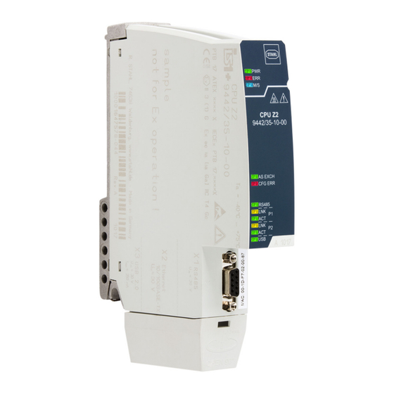
Anhang B Anhang B 15.1 Geräteaufbau Gerätelement Beschreibung Sicherungs- Torx T20 zum schraube Befestigen am Sockel LEDs Status- bzw. Fehleranzeige der CPU LEDs Status- bzw. Fehleranzeige der Kommunikation zum Automatisierungs- system LEDs Statusanzeige der Schnittstellen Sub-D-Buchse RS485 Buchse X1 Prozessbus 19622E00 Schutzkappe Schutz und... -
Seite 32: Maßangaben / Befestigungsmaße
Anhang B 15.2 Maßangaben / Befestigungsmaße Maßzeichnungen (alle Maße in mm [Zoll]) – Änderungen vorbehalten 183 [7,20] 158 [6,22] 19668E00 CPU Modul 9442/35 21455E00 19670E00 CPU Modul 9442/35 mit Sockel 9496/35 CPU Modul 9442/35 mit Sockel 9496/35 (4 Steckplätze) (3 Steckplätze) IS1+ CPU Modul für Zone 2 / Division 2 264707 / 944260310010 Reihe 9442/35... -
Seite 33: Information Zu Open Source Software
Anhang C 16.1 Information zu Open Source Software Die IS1+ 9442 CPUs der R. STAHL Schaltgeräte GmbH (im folgenden "R. STAHL") und die auf der Website von R. STAHL erhältlichen Software-Updates enthalten neben proprietärer Software auch Software von Dritten, einschließlich freier Software/Open Source Software, die unter verschiedenen Lizenzbedingungen, einschließlich GNU GPLv2, GNU GPLv3,... - Seite 35 Operating instructions Additional languages r-stahl.com IS1+ CPU module for Zone 2/Division 2 Series 9442/35...
- Seite 36 Contents Contents General Information .....................3 Manufacturer......................3 About these Instructions ..................3 Further Documents ....................3 Conformity with Standards and Regulations............3 Explanation of Symbols ..................4 Symbols used in these Operating Instructions.............4 Symbols on the Device ..................4 Safety........................5 Intended Use......................5 Personnel Qualification ..................5 Residual Risks .....................6 Transport and Storage ..................8 Product Selection and Project Engineering ............8 Terminal Assignment for Sub-D Slot X1 ..............9...
-
Seite 37: General Information
Make the operating instructions accessible to operating and maintenance staff at all times. ▶ Pass the operating instructions on to each subsequent owner or user of the device. ▶ Update the operating instructions every time R. STAHL issues an amendment. ID no.: 264707 / 944260310010 Publication code: 2023-08-24·BA00·III·en·03... -
Seite 38: Explanation Of Symbols
Explanation of Symbols Explanation of Symbols Symbols used in these Operating Instructions Symbol Meaning Handy hint for making work easier Dangerous situation which can result in fatal or severe injuries DANGER! causing permanent damage if the safety measures are not complied with. -
Seite 39: Safety
Specialists who perform these activities must have a level of knowledge that meets applicable national standards and regulations. Additional knowledge is required for any activity in hazardous areas! R. STAHL recommends having a level of knowledge equal to that described in the following standards: •... -
Seite 40: Residual Risks
▶ Do not place any loads on the device. ▶ Check the packaging and the device for damage. Report any damage to R. STAHL immediately. Do not commission a damaged device. ▶ Store the device in its original packaging in a dry place (with no condensation), and make sure that it is stable and protected against the effects of vibrations and knocks. - Seite 41 Only connect compatible components (IS1+/IS1 Remote I/O system). If in doubt, consult R. STAHL. ▶ Repair work on the device must be performed only by R. STAHL. ▶ Gently clean the device with a damp cloth only – do not use scratching, abrasive or aggressive cleaning agents or solutions.
-
Seite 42: Transport And Storage
Transport and Storage 3.3.2 Damage to electrical Components Sensitive electronic components can be damaged by electrostatic discharge (ESD). ▶ Before making contact with the device, discharge the charge to a grounded metal body. ▶ Avoid direct contact with connectors or the contacts on the module slots. ▶... -
Seite 43: Terminal Assignment For Sub-D Slot X1
Product Selection and Project Engineering Project engineering specifications depending on the ambient temperature Adjust mounting processes based on the maximum ambient temperature, see the "Technical data" chapter. Updating/replacing modules Observe chapter 6.2. Terminal Assignment for Sub-D Slot X1 For connecting the PROFIBUS DP: Pin no. -
Seite 44: Redundancy
Product Selection and Project Engineering Redundancy Depending on the communication protocol, the IS1+ Remote I/O system can also have a redundant design. Here, a distinction is made between CPU redundancy, power redundancy and system/full redundancy. Comply with the specifications for selecting the suitable 9496/35 socket and maximum equipping of the 9442/35 CPU module and 9445/35 power module! The following table shows the components required for the respective redundancy concepts: 9496/35 socket... - Seite 45 Product Selection and Project Engineering 5.4.1 Firmware Version in Redundancy Operation In redundancy operation, it is generally recommended that both 9442 CPU modules (primary and secondary module) have the same firmware version. Compare current and older firmware versions A new CPU module is always delivered with the latest firmware version. It may differ from the version already used by an older module.
-
Seite 46: Mounting And Installation
Mounting and Installation Mounting and Installation DANGER! Explosion hazard due to incorrect mounting! Non-compliance results in severe or fatal injuries. ▶ Only mount the device on clean contact surfaces. ▶ Fit the device using safety screws. ▶ Tighten the safety screws to a tightening torque of 1.5 to 1.9 Nm. Mounting/Dismounting ▶... -
Seite 47: Replacing And Upgrading The Module
Mounting and Installation Replacing and Upgrading the Module 6.2.1 Replacing the 9442/35 CPU Module ▶ Switch off the power supply to the IS1+ Remote I/O system. ▶ Disconnect the connection lines for communication (RJ45, Sub-D and USB). ▶ Use a screwdriver (Torx T20) to unscrew the safety screw (1), swivel the module forward and out (2) and disconnect it from the socket (3). -
Seite 48: Installation
Mounting and Installation 6.2.3 Upgrading the IS1 9441/15 Ethernet CPU Series to IS1+ CPU 9442/35 ▶ Switch off the power supply to the IS1 Remote I/O station. ▶ Disconnect the connection lines for communication (FO) (see 9441/15 operating instructions). ▶ Dismount the 9441/15 IS1 Ethernet CPU, 9444/15 power module and 9492 socket (see operating instructions for 9441/15 CPU, 9444 power module and 9492 socket). - Seite 49 Mounting and Installation 6.3.1 Connecting the Fieldbus ▶ 19635E00 Connect the fieldbus conductor with Sub-D plug to the X1 Sub-D slot. ▶ Secure the Sub-D connector against loosening using screws. Tightening torque 0.5 to 0.6 Nm. ▶ Secure the connection line against tensile load and scuffing. ▶...
- Seite 50 Mounting and Installation ▶ Use retaining brackets and cable ties to secure connection lines against tensile load and scuffing. While doing so, the strain relief must be fitted from a cable length of 30 cm, but ideally before. RJ45 plugs and retaining brackets are available as accessories. ▶...
-
Seite 51: Parameterisation And Commissioning
Parameterisation and Commissioning Parameterisation and Commissioning Before commissioning, carry out the following checks: ▶ Mounting and installation of the device according to regulations. ▶ Correct, secure connection of the connection lines. ▶ No damage to the device and the connection lines. ▶... - Seite 52 Insert the CPU module; see chapter 6.1.2. ▶ Switch on the power supply and wait for the system to start up. The USER password is now set to the default value: R.STAHL. ▶ Change the USER password via the web server.
-
Seite 53: Operation
Operation Operation Operation ▶ For device operation, observe the information in the "Intended use" and "Parameterisation and commissioning" chapters. Indicators LEDs on the device indicate the operating state of the device (see also the "Intended use" and "Device design" chapters). The LEDs may be continuously lit or blink in different colours. - Seite 54 Operation Operating state Description "PWR" "ERR" "M/S" "AS "CFG "STATUS" (green) (red) (blue) EXCH" ERR" (yellow) (green) (red) Data exchange No error with AS IOM collective alarm or error in redundant power module Redundant Redundant CPU CPU inactive on standby Redundant CPU data exchange with AS...
-
Seite 55: Troubleshooting
Operation Troubleshooting Error notifications can be read out using the IS1+ web browser. Status or error indication Status Cause of error Troubleshooting "PWR" LED Power supply Power supply OK – (green) Software update in "M/S" LED (blue) = progress Wait until the software update is complete No power supply Insert the power... - Seite 56 Operation Status Cause of error Troubleshooting "M/S" LED Requires Overtemperature/ Change the ambient (blue) maintenance/ subnormal temperature temperature or ensure outside the better ventilation "PWR" LED (green) = specification (shading/heating) : Temperature too high or too low Redundant power Remove power module module inserted but not or change CPU configured...
- Seite 57 Operation Status Cause of error Troubleshooting "AS EXCH" LED Data exchange Data exchange + – (green) with master CPU active Data exchange + – CPU inactive (only for redundant CPUs) No data exchange with • Start cyclical data master exchange with the master •...
- Seite 58 Ethernet line If the error cannot be eliminated using the specified procedures: ▶ Contact R. STAHL Schaltgeräte GmbH. For rapid processing, have the following information ready: • Type and serial number of the device • DCS/PLC • Protocol •...
-
Seite 59: Maintenance, Overhaul, Repair
Returning the Device ▶ Only return or package the devices after consulting R. STAHL! Contact the responsible representative from R. STAHL. R. STAHL's customer service is available to handle returns if repair or service is required. ▶ Contact customer service personally. ▶... -
Seite 60: Cleaning
NOTICE! Malfunction or damage to the device due to the use of non-original components. Non-compliance can result in material damage. ▶ Use only original accessories and spare parts from R. STAHL Schaltgeräte GmbH (see data sheet). IS1+ CPU module for Zone 2/Division 2... -
Seite 61: Appendix A
Appendix A Appendix A 14.1 Technical Data Explosion protection Global (IECEx) IECEx PTB 17.0031X Ex ec ia [ia Ga] IIC T4 Gc Europe (ATEX, UKEX) PTB 17 ATEX 2019 X, CML 21UKEX2873X E II 3 (1) G Ex ec ia [ia Ga] IIC T4 Gc Certificates and approvals Certificates IECEx, ATEX, UKEX, cFMus (Canada, USA), KTL (South Korea),... - Seite 62 Appendix A Technical data X2 10/100BASE-TX interface Connection 2 x RJ45 plug, 100BASE-TX, unmanaged switch function Protocols Modbus TCP, PROFINET, EtherNet/IP (can be selected by the user using the rotary switch on the 9496/35 socket) IP address setting for Manual or DHCP assignment (can be selected by the user via a web server ServiceBus or IS1+ detect software.
- Seite 63 Manufacturer, type, hardware revision, software revision, serial number parameters Connectable software • IS Wizard (using the USB ServiceBus) packages • R. STAHL DTM devices with FDT frames (e.g. FDT container by M+M; PACTware) • AMS from Emerson Process Management • PDM from Siemens •...
- Seite 64 9496/35-04 CPU module with socket: L = 167 mm, W = 152 mm, H = 152 mm Mounting/installation Installation conditions Mounting type On 9496/35 socket Mounting orientation Horizontal or vertical For further technical data, see r-stahl.com. IS1+ CPU module for Zone 2/Division 2 264707 / 944260310010 Series 9442/35 2023-08-24·BA00·III·en·03...
-
Seite 65: Appendix B
Appendix B Appendix B 15.1 Device Design Device element Description Safety screw Torx T20 for mounting on the socket LEDs Status or error indication of the CPU LEDs Status or error indication of communication to the automation system LEDs Status indication of the interfaces Sub-D socket X1 RS485 Sub-D... -
Seite 66: Dimensions/Fastening Dimensions
Appendix B 15.2 Dimensions/Fastening Dimensions Dimensional drawings (all dimensions in mm [inch]) – Subject to change 183 [7,20] 158 [6,22] 19668E00 9442/35 CPU module 21455E00 19670E00 9442/35 CPU module with 9496/35 socket 9442/35 CPU module with 9496/35 socket (4 slots) (3 slots) IS1+ CPU module for Zone 2/Division 2 264707 / 944260310010... -
Seite 67: Appendix C
We shall not be held liable for any damage resulting from modifications to parts of the software or their configuration that were not carried out by R. STAHL. In addition, R. STAHL shall not be held liable if the open source software infringes on the copyright of a third party. - Seite 69 Ne pas débrancher l’équipement en présence d’atmosphère inflammable ou combustible. AVERTISSEMENT: CPU Module, Type 9442/35-10-00 none Power Module, Type 9445/35-12 Vertretung Agency Socket 9496/35-0d-00 (d = 3,4) 03.05.2023 Bagusch 9442 6 031 002 1 22.02.2021 T. Stahl 1 of 1 08.03.2018 Bagusch...
- Seite 70 Examples for System Topology interfacing The IS1+ Remote I/O System is a DIN rail mounted system designed Automation control systems with DIV 2 / Zone 2 to record and output process control signals between hazardous installation of IS1+ Remote I/O System: location transducers and sensors and a nonhazardous location automation system.
- Seite 71 2018 08.03. Bagusch IS1+ Remote I/O System Kaiser for CL I, DIV 2 / Zone 2 2 of 2 Overview 9400 6 031 006 1...