HEIDENHAIN LIP 281 R Montageanleitung

Verwandte Anleitungen für HEIDENHAIN LIP 281 R


Inhaltszusammenfassung für HEIDENHAIN LIP 281 R
- Seite 1 Montageanleitung Mounting Instructions Instructions de montage Istruzioni di montaggio Instrucciones de montaje LIP 281 R 7/2012...
- Seite 2 Inhalt Seite Page Contents 3 Warnhinweise 3 Warnings Sommaire 6 Lieferumfang 6 Items Supplied Indice 8 Hinweise zur Montage 8 Mounting Procedure Índice 10 Abmessungen 10 Dimensions 12 Anbau des Maßstabs 12 Mounting the Scale 16 Anbau des Abtastkopfes 16 Mounting the Scanning Head 18 Justage 18 Adjustment 26 Abschließende Arbeiten...
- Seite 3 Warnhinweise Warnings Avertissement Avvertenze Advertencias Achtung: Die Montage und Inbetriebnahme ist von einer Fachkraft für Elektrik und Feinmechanik unter Beachtung der örtlichen Sicherheitsvorschriften vorzunehmen. Die Steckverbindung darf nur spannungsfrei verbunden oder gelöst werden. Der Antrieb darf während der Montage nicht in Betrieb gesetzt werden. Note: Mounting and commissioning is to be conducted by a specialist in electricity and precision mechanics under compliance with local safety regulations.
- Seite 4 Vorsicht: Unsichtbare Laserstrahlung! Nicht der Strahlung aussetzen. Caution: Invisible laser radiation! Avoid exposure to beam. Attention: rayonnement laser invisible! Ne pas exposer au rayonnement. Attenzione: raggio laser invisbile! non spostare il raggio. ¡Atención: Radiación láser invisible! No exponerse a la radiación.
- Seite 5 Messgerät nicht fallen lassen oder größeren Erschütterungen aussetzen. Do not drop the encoder. Do not subject it to strong impact. Ne pas faire tomber l'appareil ou lui faire subir des secousses importantes. Non far cadere il sistema di misura né esporlo a eccessive vibrazioni.
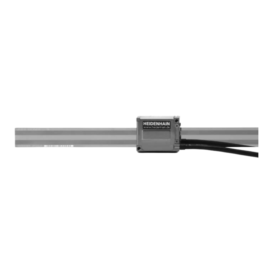
- Seite 6 Lieferumfang Items Supplied Objet de la fourniture Standard di fornitura Suministro a) Maßstab LIP 201 R b) Abtastkopf LIP 28 R a) LIP 201 R linear scale b) LIP 28 R scanning head a) Règle de mesure LIP 201 R b) Tête captrice LIP 28 R a) Riga graduata LIP 201 R b) Testina di scansione LIP 28 R...
- Seite 7 Separat bestellen: a) Spannpratzen zur Befestigung des Maßstabs. Anzahl je nach Messlänge. b) Spannpratze thermischer Fixpunkt c) Zwischenplatte d) Zwischenplatte (stapelbar) To be ordered separately: a) Fixing clamps for mounting the scale. Number depends on the ML. b) Fixing clamp for thermal fi xed point. c) Spacer d) Spacer (stackable) Commander séparément :...
- Seite 8 Hinweise zur Montage Mounting Procedure Remarques sur le montage Avvertenze per il montaggio Indicaciones para el montaje Achtung: Anbau so wählen, dass der maximale Verfahrweg innerhalb der Messlänge ML des Maßstabs liegt. Bei Überschreitung kann schädliche Laserstrahlung austreten! Caution: Choose a mounting position such that the maximum traverse range is within the measuring length ML of the scale.
- Seite 9 Maßstab so anbauen, dass Teilung vor direkter Verschmutzung geschützt ist. Eventuell besondere Schutzvorrichtung vorsehen. Mount the scale so that the graduation is protected from direct contamination. If necessary, fi t a protective cover over the scale. Monter la règle de mesure de telle sorte que la division soit protégée des salissures.
- Seite 10 Abmessungen Dimensions Dimensions Dimensioni Dimensiones < ML † 70 ML – 4 70 < ML † 100 n – 1 100 < ML † 200...
- Seite 11 Maschinenführung Maßstablänge Machine guideway Length of scale Guidage de la machine Longueur de la règle de mesure Guida della macchina Lunghezza riga Longitud de escala Guía de la máquina À = Referenzmarken-Lage Montageelement für Hartklebung zur Defi nition des thermischen Fixpunktes Reference mark position Mounting element for hard adhesive bond in order to defi...
- Seite 12 Anbau des Maßstabs Mounting the Scale Montage de la règle de mesure Montaggio della riga Fijación de la escala Anbautoleranzen F = Maschinenführung Mounting tolerances F = machine guideway Tolérances de montage F = Guidage de la machine Tolleranze di montaggio F = Guida della macchina Tolerancias de montaje F = Guía de máquina...
- Seite 13 Anschlagstifte verwenden. Abstand max. 200 mm, Bohrbild der Spannpratzen und Halter thermischer Fixpunkt beachten. Use stop pins. Max. distance 200 mm; keep in mind the hole pattern of the fi xing clamps and the fi xture for the thermal fi xed point. Utiliser les goupilles de butée.
- Seite 14 Schutzfolie abziehen. Maßstab vorsichtig auf die Anschlagstifte legen, Spannpratzen leicht andrücken und befestigen. Anschlagstifte entfernen. Remove the protective fi lm. Carefully place the scale onto the stop pins, gently press the fi xing clamps into place and secure them. Remove the stop pins. Enlever le fi...
- Seite 15 Bei Verwendung des Fixpunktes: Bohrung für Halter thermischer Fixpunkt mittig der Messlänge positionieren. Mittig positionierte Spannpratze mit Halter thermischer Fixpunkt ersetzen. If using the fi xed point: Position the hole for the fi xture for the thermal fi xed point at midpoint of measuring length. If there is a fi xing clamp at midpoint of the measuring length, replace it with the fi...
- Seite 16 Anbau des Abtastkopfes Mounting the Scanning Head Montage de la tête captrice Montaggio della testina Fijación del cabezal captador Anbaufl äche Mounting surface Surface de montage Superfi cie di montaggio Superfi cie de montaje –6 –1 À = Für optimale Driftstabilität bei Temperaturänderung in Stahl (Þ 10 ·...
- Seite 17 Thermische Anbindung (Überstand wird eingefedert): Á = Deckelprägung mit Überstand max. 0,4 mm  = Überstand Deckellasche max 0,7 mm Thermal connection (protruding part is pressed in): Á = Flexible cover protrudes partially by max 0.4 mm  = Cover tab protrudes by max 0.7 mm Liaison thermique (dépassement compressé): Á...
- Seite 18 Justage und Abgleich Adjustment Ajustage et réglage Taratura e regolazione Ajuste y reglaje Benötigte Messmittel zur Justage: • ATS-Software • PWM 20 • Measuring equipment required for adjustment: • ATS software • PWM 20 • Outils de mesure nécessaires au réglage: •...
- Seite 19 Installation der ATS-Justage- und Test-Software (siehe Bedienungsanleitung PWM 20). Installation of ATS adjusting and testing software (see PWM 20 Operating Instructions). Installation du logiciel de réglage ATS et de test (voir le manuel d'utilisation PWM 20). Installazione del software di taratura ATS e di prova (vedere Istruzioni per l'uso PWM 20).
- Seite 20 Nach der Installation ATS-Software starten und Anweisungen der Software bis Schritt 2 beachten. After installation, start the ATS software and follow the instructions of the software until Step 2. Après l'installation, démarrer le logiciel ATS et suivre les instructions jusqu'à l'étape 2. Al termine dell'installazione avviare il software ATS e attenersi alle istruzioni del software fi...