
Inhaltszusammenfassung für Icy Box IB-EW205B-T
- Seite 1 IB-EW205B-T Manual IB-EW205B-T Electrically height-adjustable sit-stand desk frame Handbuch IB-EW205B-T Elektrisch höhenverstellbares Sitz-Steh-Tischgestell...
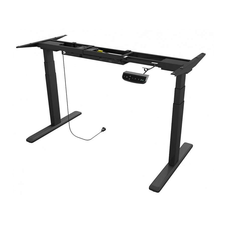
- Seite 2 Preface This electric height-adjustable table frame consists of a heavy-duty metal frame and a motorised height adjustment system. Please read these instructions completely before installation to ensure safe and correct use and to avoid damage to the electronics or the table frame. Please read carefully the following information to prevent injuries, damage to ma- •...
-
Seite 3: Package Content
Package content... -
Seite 4: Installation
Preparation Installation Requirements Required tools Recommendation Make sure there is enough space for assembly and spread out a blanket if necessary. • Place the table top (not included in the scope of delivery) carefully with the top side on the blanket. Note before assembly •... - Seite 5 Adjustment of the frame • Make sure that the frame is positioned in the middle on the tabletop. • Then adjust the frame to the tabletop (adjustment as described above). Loosen the hex head screws (do not unscrew them completely) to adjust the crossbar and then tighten them again 35( m a x ) 0( m i n )
- Seite 6 Pre-drilling the mounting holes Use the cordless screwdriver with a drill to drill guide holes through the side brackets into the underside of the table top. Note: The drill holes should be at least 10 mm deep and the drill diameter should be less than 3 mm Re-tighten all the hex head screws to complete the adjustment.
- Seite 7 Assembling the lifting columns Assembling the feet • Insert one lifting column into one end of the crossbar with the head Place a foot on the bottom of the lifting column. Align the mounting of the lifting column facing inward. Make sure the mounting holes holes on the foot with the screw holes on the lifting column.
- Seite 8 Assembling the fixing plate Attaching the control box • Turn over the desk frame with the crossbar facing up. At least two people are • Align the mounting holes on the fixing plate with the screw holes as shown. required when turning over the desk frame. If only one person turns over the •...
- Seite 9 Assembling the cable management tray • The arrow on the fixing plate indicates the direction of sliding in the control box. Follow the direction of the arrow to mount the control box. • Slide the control box to the center of fixing plate. •...
- Seite 10 Assembling the desktop Attach the ten anti-vibration pad (S-H) to the surface of the crossbar at the ten positions as shown. Tighten the thumbscrews on the tray hangers.
- Seite 11 • Align the previously drilled screw holes with the mounting holes on the crossbar. Insert and tighten the 4 screws (S-C) from below. • Repeat the same process to assemble the other side of the desktop.
-
Seite 12: Height Adjustment
floor, the table frame can be aligned by turning the foot pads. can now use it with the touch controller. Tip: Use a bubble level to align the table frame. Note: Further instructions for the touch controller follow directly afterwards. IB-EW205B-T... - Seite 13 Digital Touch Control Panel Installation instruction & user guide Reset the system: • To reset the system, press and hold the “Up” and “Down” buttons simultaneously. The unit emits one beep and the display shows “ ” and the desk starts moving downward to the lowest position. Do not release the buttons until the unit emits a second beep. The desk will move upward a little and the display shows the current desk height.
- Seite 14 Troubleshooting Guide Custom Programming Guide Before E01/E07 Electrical problem has occurred. Plug out the power and re-plug. System overheating. Stop operating and allow your desk to remain idle for approximately 18 minutes. The columns don’t go together. Reset the system. The control panel is disconnected.
-
Seite 15: Verpackungsinhalt
Verpackungsinhalt Inbusschraube Inbusschraube Kreuzschlitzschraube Traverse Seitenschienen Hubsäulen Füße Kreuzschlitzschraube Kreuzschlitzschraube Kreuzschlitzschraube Kabel-Clip Anti-Vibrationsunterlage Inbusschlüssel Befestigungsplatte Steuergerät Netzstecker Kabelmanagement Die Abbildung des Controllers dient nur als Beispiel. Das tatsächliche Produkt kann abweichen. Halter Kabelmanagement Controller... -
Seite 16: Arbeitsvorbereitung
Arbeitsvorbereitung Montage Vorrausetzung Max. Belastung Stromanschluss Betriebstemperatur Decke 125 kg (-5°C bis +40°C) Benötigte Werkzeuge Wasserwaage Inbusschlüssel Akkuschrauber Kreuzschlitz- (enthalten) schraubendreher Empfehlung Eine Transportdecke, um Kratzer und Beschädigun- gen am Gestell oder Boden zu vermeiden. Sorgen Sie für ausreichend Platz zur Montage und breiten Sie ggf. eine Decke aus. •... - Seite 17 Einstellung des Rahmens • Stellen Sie sicher, dass der Rahmen in der Mitte auf der Tischplatte positioniert ist. • Passen Sie den Rahmen an die Tischplatte an (Verstellung wie oben beschrieben). Lösen Sie die Inbusschrauben (nicht ganz herausdrehen) zum Verstellen der Hauptschiene und ziehen Sie diese anschließend wieder fest.
-
Seite 18: Vorbohren Der Befestigungslöcher
Vorbohren der Befestigungslöcher Verwenden Sie den Akkuschrauber mit einem Bohrer, um Führungslöcher durch die Seitenschienen in die Unterseite der Tischlatte zu bohren. Hinweis: Die Tiefe der Bohrlöcher sollte mind. 10 mm und der Bohrerdurchmesser max. 3 mm betragen. Akkuschrauber Um die Einstellung abzuschließen, ziehen Sie alle gelösten Inbusschrauben wieder fest. -
Seite 19: Montage Der Hubsäulen
Montage der Hubsäulen Montage der Füße • Positionieren Sie die Hubsäulen am Ende der Seitenschienen wie Setzen Sie den Fuß auf die Hubsäule und richten Sie die Schraubenlö- abgebildet. Stellen Sie sicher, dass die Löcher an den Hubsäulen cher aufeinander aus. mit denen der Traverse vollständig übereinstimmen. -
Seite 20: Montieren Der Befestigungsplatte
Montieren der Befestigungsplatte Montage des Steuergerätes • Drehen Sie das Tischgestell mit der Traverse nach oben um. Zum Wenden des • Richten Sie die Befestigungslöcher auf der Befestigungsplatte wie abgebildet auf die Schraubenlöcher aus. Tischgestells sind mindestens zwei Personen erforderlich. Bei nur einer Person •... - Seite 21 Montage des Kabelmanagements • Der Pfeil auf der Befestigungsplatte zeigt die Einschubrichtung des Steuergerätes an. Folgen Sie der Pfeilrichtung, um das Steuergerät zu montieren. • Richten Sie die Befestigungslöcher der Kabelmanagement Halter (I) • Schieben Sie das Steuergerät in die Mitte der Befestigungsplatte. auf die des Kabelmanagements aus.
-
Seite 22: Montage Der Tischplatte
Montage der Tischplatte Montieren Sie die Anti-Vibration Pads (S-H) an den dafür vorgesehenen Stellen an der Traverse und den Seitenschienen. Ziehen Sie die Rändelschrauben an den Kabelmanagement-haltern fest. - Seite 23 • Richten Sie die zuvor gebohrten Führungslöcher der Tischlatte an den Löchern der Seitenhalter aus und befestigen Sie diese mit den 4 Schrauben (S-C) und ziehen Sie die Schrauben fest. • Wiederholen Sie den Vorgang auf der anderen Seite der Tischplatte. Kreuzschlitz- Akku- schraubendreher...
- Seite 24 Boden stehen, kann durch Drehen der Fußpads das Tischgestell ausgerichtet werden. können dieses jetzt unter Verwendung des Touch-Controllers verwenden. Tipp: Nutzen Sie zum Ausrichten des Tischgestells eine Wasserwaage. Hinweis: Eine weitere Anleitung für den Touch-Contoller folgt direkt im Anschluss. Wasserwaage IB-EW205B-T...
- Seite 25 Digital Touch-Control Panel Bedienungsanleitung System zurücksetzen: • Um das System zurückzusetzen, halten Sie die Tasten "Auf" und "Ab" gleichzeitig gedrückt. Das Gerät gibt einen Signalton aus und das Display zeigt “ ” und das Pult fährt nach unten in die unterste Position. Lassen Sie die Tasten nicht los, bis das Gerät wieder einen Piepton abgibt. Der Tisch fährt ein Stück nach oben und das Display zeigt die aktuelle Tischhöhe an.
-
Seite 26: Benutzerdefinierte Programmierung
Fehlerbehebung Benutzerdefinierte Programmierung Diese Reparaturanleitung soll Ihnen helfen, Fehlfunktionen zu erkennen und zu beheben, die während des Betriebes des Vorher elektrisch höhenverstellbaren Sitz-Steh-Tischgestells auftreten könnten. Tastenfunktion Wenn die folgende Anleitung die Fehlfunktion nicht beheben kann, wenden Sie sich bitte über Ihren Verkäufer an den Service für einen eventuellen Austausch des Zubehörs.