Ducati Performance 97180271A Montageanleitung
Rennstreckenverkleidung vorne
Inhaltsverzeichnis
Quicklinks
Superbike 1299 / 1299S
Kit carene/cupolino pista
Racing fairing/headlight fairing kit
Simbologia
Per una lettura rapida e razionale sono stati impiegati simboli che
evidenziano situazioni di massima attenzione, consigli pratici o
semplici informazioni.
Prestare molta attenzione al significato dei simboli, in quanto la
loro funzione è quella di non dovere ripetere concetti tecnici o
avvertenze di sicurezza. Sono da considerare, quindi, dei veri e
propri "promemoria" .
Consultare questa pagina ogni volta che sorgeranno dubbi sul loro
significato.
Attenzione
La non osservanza delle istruzioni riportate può creare una
situazione di pericolo e causare gravi lesioni personali e anche la
morte.
Importante
Indica la possibilità di arrecare danno al veicolo e/o ai suoi
componenti se le istruzioni riportate non vengono eseguite.
Note
Fornisce utili informazioni sull'operazione in corso.
Riferimenti
I particolari evidenziati in grigio e riferimento numerico (Es.
rappresentano l'accessorio da installare e gli eventuali componenti
di montaggio forniti a kit.
I particolari con riferimento alfabetico (Es.
componenti originali presenti sul motoveicolo.
Tutte le indicazioni destro o sinistro si riferiscono al senso di marcia
del motociclo.
Avvertenze generali
Attenzione
Le operazioni riportate nelle pagine seguenti devono essere
eseguite da un tecnico specializzato o da un'officina autorizzata
DUCATI.
Attenzione
Le operazioni riportate nelle pagine seguenti se non eseguite a
regola d'arte possono pregiudicare la sicurezza del pilota.
Note
Documentazione necessaria per eseguire il montaggio del Kit
è il MANUALE OFFICINA, relativo al modello di moto in vostro
possesso.
Note
Nel caso fosse necessaria la sostituzione di un componente del kit
consultare la tavola ricambi allegata.
1
)
A
) rappresentano i
ISTR - 692 / 00
Symbols
To allow quick and easy consultation, this manual uses graphic
symbols to highlight situations in which maximum care is required,
as well as practical advice or information.
Pay attention to the meaning of the symbols since they serve to
avoid repeating technical concepts or safety warnings throughout
the text. The symbols should therefore be seen as real reminders.
Please refer to this page whenever in doubt as to their meaning.
Warning
Failure to follow these instructions might give raise to a dangerous
situation and provoke severe personal injuries or even death.
Caution
Failure to follow these instructions might cause damages to the
vehicle and/or its components.
Notes
Useful information on the procedure being described.
References
Parts highlighted in grey and with a numeric reference
1
(Example
) are the accessory to be installed and any assembly
components supplied with the kit.
Parts with an alphabetic reference (Example
components fitted on the vehicle.
Any right- or left-hand indication refers to the vehicle direction of
travel.
General notes
Warning
Carefully perform the operations on the following pages since they
might negatively affect rider safety.
Warning
Carefully perform the operations on the following pages since they
might negatively affect rider safety.
Notes
The following documents are necessary for assembling the Kit:
WORKSHOP MANUAL of your bike model.
Notes
Should it be necessary to change any kit parts, please refer to the
attached spare part table.
97180271A
A
) are the original
1
Inhaltsverzeichnis

Verwandte Anleitungen für Ducati Performance 97180271A


Inhaltszusammenfassung für Ducati Performance 97180271A
- Seite 1 Le operazioni riportate nelle pagine seguenti devono essere Warning eseguite da un tecnico specializzato o da un’officina autorizzata Carefully perform the operations on the following pages since they DUCATI. might negatively affect rider safety. Attenzione Notes Le operazioni riportate nelle pagine seguenti se non eseguite a The following documents are necessary for assembling the Kit: regola d’arte possono pregiudicare la sicurezza del pilota.
- Seite 2 Attenzione Warning Il presente kit è per utilizzo esclusivo su pista (esempio: gare This kit is for racing use only (e.g.: competitive trials on tracks). sportive su circuiti). After mounting this exhaust kit, the vehicle cannot be used on Dopo il montaggio del kit, il motoveicolo non può circolare su public roads.
- Seite 3 Attenzione Warning Il presente kit è per utilizzo esclusivo su pista (esempio: gare This kit is for racing use only (e.g.: competitive trials on tracks). sportive su circuiti). After mounting this exhaust kit, the vehicle cannot be used on Dopo il montaggio del kit, il motoveicolo non può circolare su public roads.
- Seite 4 Smontaggio componenti originali Removing the original components Smontaggio specchi retrovisori Removing the rear-view mirrors Svitare le n.2 viti (C1) di fissaggio dello specchio retrovisore sinistro Loosen no.2 screws (C1) fastening LH rear-view mirror (C). (C). Separate LH rear-view mirror (C) from headlight fairing (E) paying Separare lo specchio retrovisore sinistro (C) dal cupolino (E) attention to the wiring.
- Seite 5 Smontaggio cover blocco chiave Removing the ignition switch cover Svitare i n.2 dadi speciali (F1) e le n.2 viti (F2) di fissaggio della Loosen no.2 special nuts (F1) and no.2 screws (F2) fastening cover blocco chiave (F). ignition switch cover (F). Rimuovere la cover blocco chiave (F).
- Seite 6 Smontaggio copriconvogliatori Removing the conveyor covers Importante Caution Durante le fasi di smontaggio dei copriconvogliatori destro (G) e When removing RH conveyor cover (G) and LH conveyor cover sinistro (H), è necessario proteggere il serbatoio carburante al fine (H), it is necessary to protect the fuel tank from any damage or di salvaguardarlo da eventuali graffi o danneggiamenti.
- Seite 7 Smontaggio semicarena inferiore sinistra e cavalletto Removing the LH lower half-fairing and side stand Svitare le viti (L4) e (L5) di fissaggio della semicarena inferiore Loosen screws (L4) and (L5) securing LH lower half-fairing (L) at sinistra (L) nella parte inferiore. the bottom.
- Seite 8 Smontaggio semicarena inferiore destra Removing the RH lower half-fairing Svitare la vite (P4) di fissaggio della semicarena inferiore destra (P) Loosen screw (P4) securing RH lower half-fairing (P) at the bottom. nella parte inferiore. Loosen screw (P3) securing RH lower half-fairing (P) in the front Svitare la vite (P3) di fissaggio anteriore interno della semicarena inner part.
- Seite 9 Smontaggio semicarena superiore sinistra Removing the LH upper half-fairing Svitare le n.4 viti (A1) con rosette (A2) di fissaggio della semicarena Loosen no.4 screws (A1) with washers (A2) fastening LH upper superiore sinistra (A). half-fairing (A). Svitare la vite (A4) di fissaggio posteriore della semicarena inferiore Loosen screw (A4) securing LH lower half-fairing (A) at the rear.
- Seite 10 Smontaggio semicarena superiore destra Removing the RH upper half-fairing Svitare le n.4 viti (B1) con rosette (B2) di fissaggio della semicarena Loosen no.4 screws (B1) with washers (B2) fastening RH upper superiore destra (B). half-fairing (B). Svitare la vite (B4) di fissaggio posteriore della semicarena inferiore Loosen screw (B4) securing RH lower half-fairing (B) at the rear.
- Seite 11 Smontaggio paratia inferiore cupolino Removing the headlight fairing lower cover Note Notes Per comprendere meglio lo smontaggio della paratia inferiore (I) To better understand how to remove lower cover (I) the front non vengono rappresentati il parafango e la ruota anteriori. mudguard and wheel are not shown.
- Seite 12 Smontaggio cupolino Removing the headlight fairing Rimuovere la fascetta (E5) e liberare il ramo anteriore del cablaggio Remove clamp (E5) and release main wiring front branch (D) from principale (D) dal cupolino (E). headlight fairing (E). Svitare le n.2 viti (E3) su entrambi i lati del telaietto supporto faro Loosen no.2 screws (E3) on both sides of motorcycle headlight del motoveicolo.
- Seite 13 Svitare le n.8 viti (E6) con rosetta (E7) ed i relativi n.8 dadi gommati Loosen no.8 screws (E6) with washer (E7) and the relevant (E12) e rimuovere il plexiglass (E8) dal cupolino (E). no.8 rubber-coated nuts (E12) and remove windscreen (E8) from Recuperare le n.8 viti (E6) con rosetta (E7) e il plexiglass (E8).
- Seite 14 ISTR 692 / 00...
- Seite 15 Smontaggio corpo fanale anteriore a lampade (1299) Removing the bulb-type headlight (1299) Svitare le n.2 viti (O2) ed estrarre il corpo fanale anteriore (O). Loosen the no.2 screws (O2) and remove the headlight body (O). Scollegare i connettori delle luci abbaglianti (O3) ed (O4) e Disconnect high beam (O3) and (O4) connectors as well as low anabbaglianti (O5) ed (O6).
- Seite 16 5 Nm ± 10% Montaggio componenti kit Kit installation Importante Caution Verificare, prima del montaggio, che tutti i componenti risultino Check that all components are clean and in perfect condition puliti e in perfetto stato. before installation. Adottare tutte le precauzioni necessarie per evitare di danneggiare Adopt any precaution necessary to avoid damages to any part of qualsiasi parte nella quale ci si trova ad operare.
- Seite 17 3 Nm ± 10% 1 Nm ± 10% 3 Nm ± 10% 3 Nm ± 10% 1 Nm ± 10% 4 Nm ± 10% 1 Nm ± 10% 4 Nm ± 10% 1 Nm ± 10% 4 Nm ± 10% Preassemblaggio gruppo cover fanale anteriore Pre-assembling the headlight cover Montare il gommino (29) sul foro centrale del coperchio convogliatore...
- Seite 18 5 Nm ± 10% 5 Nm ± 10% ISTR 692 / 00...
- Seite 19 Montaggio cover fanale anteriore per versioni con fanale Installing the headlight cover for versions equipped with anteriore a lampade (1299) bulb-type headlight (1299) Collegare il connettore (O12) al sensore temperatura (O14) e Connect connector (O12) to temperature sensor (O14) and fit cap montare il tappo (10A) sul connettore della luce di posizione (O11) (10A) onto parking light connector (O11) present on main wiring presente sul ramo anteriore cablaggio principale.
- Seite 20 0,2 Nm ± 10% 0,2 Nm ± 10% 0,2 Nm ± 10% 0,2 Nm ± 10% Premontaggio cupolino Headlight fairing pre-assembly Posizionare il plexiglass originale (E8) inserendone il bordo inferiore Position original windscreen (E8) by fitting the lower edge under al di sotto del profilo del cupolino (1).
- Seite 21 5 Nm ± 10% 5 Nm ± 10% Montaggio cupolino Headlight fairing assembly Posizionare il ramo cablaggio principale (D) sulla cleat cablaggio Lay main wiring harness (D) on instrument panel wiring cleat (19) cruscotto (19) e fissarlo utilizzando n.2 fascette a strappo grande and fasten it using no.2 big self-locking ties (V), as shown in the (V), come indicato nel riquadro.
- Seite 22 5 Nm ± 10% 5 Nm ± 10% Rimontaggio paratia inferiore cupolino Refitting the headlight fairing lower cover Note Notes Per comprendere meglio il rimontaggio della paratia inferiore (I) non To better understand how to refit lower cover (I) the front vengono rappresentati il parafango e la ruota anteriori.
- Seite 23 2,5 Nm ± 10% 2,5 Nm ± 10% 2,5 Nm ± 10% 0,4 Nm ± 10% Montaggio semicarena superiore destra Installing the RH upper half-fairing Montare la clip (5) sul posteriore della semicarena superiore destra Install clip (5) on RH upper half-fairing (2) rear end. (2).
- Seite 24 2,5 Nm ± 10% 2,5 Nm ± 10% 2,5 Nm ± 10% 0,4 Nm ± 10% Montaggio semicarena superiore sinistra LH upper half-fairing assembly Montare la clip (5) sul posteriore della semicarena superiore destra Install clip (5) on RH upper half-fairing (12) rear end. (12).
- Seite 25 2,5 Nm ± 10% 2,5 Nm ± 10% 2,5 Nm ± 10% 2,5 Nm ± 10% 2,5 Nm ± 10% Montaggio semicarena inferiore destra Installing the RH lower half-fairing Montare le n.5 clip (5) sulla semicarena inferiore destra (14). Fit the no.5 clips (5) to RH lower half-fairing (14). Applicare la protezione adesiva termoriflettente (8) sulla parte Apply the adhesive heat reflective protection (8) inside the rear end interna posteriore della semicarena inferiore destra (14).
- Seite 26 25 Nm ± 10% 2,5 Nm ± 10% 2,5 Nm ± 10% 2,5 Nm ± 10% 2,5 Nm ± 10% 2,5 Nm ± 10% 2,5 Nm ± 10% 2,5 Nm ± 10% Montaggio semicarena inferiore sinistra e distanziali Installing the LH lower half-fairing and side stand spacers cavalletto Fit the no.2 spacers (9) in-between bracket (W) and start the no.2 Interporre i n.2 distanziali (9) tra la staffa (W) e impuntare le n.2 viti...
- Seite 27 Rimontaggio copriconvogliatori Refitting the conveyor covers Importante Caution Durante le fasi di rimontaggio dei copriconvogliatori destro (G) e When refitting RH conveyor cover (G) and LH conveyor cover sinistro (H), è necessario proteggere il serbatoio carburante al fine (H), it is necessary to protect the fuel tank from any damage or di salvaguardarlo da eventuali graffi o danneggiamenti.
- Seite 28 2,5 Nm ± 10% 8 Nm ± 10% 2,5 Nm ± 10% Rimontaggio cover blocco chiave Refitting the ignition switch cover Posizionare la cover blocco chiavi (F) inserendo, nei fori delle n.2 Position ignition switch cover (F) by inserting the threaded stud poppette (F3), le colonnette filettate (J).
- Seite 29 6 Nm ± 10% Montaggio cover Cover assembly Inserire il cavo cablaggio (D1) nella gola del telaietto anteriore (S). Fit wiring cable (D1) in the groove on front subframe (S). Montare la guarnizione (11B) sulla cover sinistra (11A). Fit seal (11B) on LH cover (11A). Posizionare la cover sinistra (11A) in corrispondenza dell'asola Position LH cover (11A) on the slot of headlight fairing (1) and start posta sul cupolino (1) e impuntare le n.2 viti (11C).
- Seite 30 NOTE / NOTES ISTR 692 / 00...
- Seite 31 Superbike 1299 / 1299S ISTR - 692 / 00 97180271A Kit carénages/bulle piste Kit Verkleidung/Cockpitverkleidung Racing Symboles Symbole Pour faciliter la consultation de ce manuel, des symboles signalent Zum schnellen und übersichtlichen Lesen werden Symbole des situations exigeant le maximum d'attention, des conseils verwendet, die außerordentlich wichtige Situationen, praktische pratiques ou de simples informations.
- Seite 32 Attention Achtung Ce kit est pour une utilisation exclusivement sur piste (ex. Das vorliegende Kit ist ausschließlich zur Anwendung auf der compétition sportive sur circuit). Rennstrecke ausgelegt (Beispiel: Rennen auf Rennbahnen). Après l’installation du kit, le motocycle ne peut pas circuler sur des Nach der Montage des Auspuffkits darf das Motorrad nicht mehr voies publiques.
- Seite 33 Attention Achtung Ce kit est pour une utilisation exclusivement sur piste (ex. Das vorliegende Kit ist ausschließlich zur Anwendung auf der compétition sportive sur circuit). Rennstrecke ausgelegt (Beispiel: Rennen auf Rennbahnen). Après l’installation du kit, le motocycle ne peut pas circuler sur des Nach der Montage des Auspuffkits darf das Motorrad nicht mehr voies publiques.
-
Seite 34: Ausbau Der Original-Bestandteile
Dépose composants d'origine Ausbau der Original-Bestandteile Dépose des rétroviseurs Abnahme der Rückspiegel Desserrer les 2 vis (C1) de fixation du rétroviseur gauche (C). Die 2 Befestigungsschrauben (C1) des linken Rückspiegels (C) Séparer le rétroviseur gauche (C) de la bulle (E) en faisant attention lösen. -
Seite 35: Abnahme Der Zündschlüsselblockabdeckung
Dépose du cover barillet clé de contact Abnahme der Zündschlüsselblockabdeckung Desserrer les 2 écrous spéciaux (F1) et les 2 vis (F2) de fixation du Die 2 Spezialmuttern (F1) und die 2 Befestigungsschrauben (F2) cover barillet clé de contact (F). der Zündschlüsselblockabdeckung (F) lösen. Déposer le cover barillet clé... -
Seite 36: Abnahme Der Luftkanalverkleidungen
Dépose des caches-déflecteurs Abnahme der Luftkanalverkleidungen Important Wichtig Pendant les phases de dépose des caches-déflecteurs droit (G) Während der Abnahme der rechten (G) und linken et gauche (H), il faut protéger le réservoir de carburant contre les Luftkanalverkleidungen (H) muss der Tank geschützt werden, um égratignures ou dommages éventuels. - Seite 37 Dépose demi-carénage inférieur gauche et béquille Abnahme der unteren linken Verkleidungshälfte und der Ständers Desserrer les vis (L4) et (L5) de fixation du demi-carénage inférieur gauche (L) dans la partie inférieure. Die Befestigungsschrauben (A4) und (A5) der unteren linken Desserrer la vis (L3) de fixation partie avant interne du demi- Verkleidungshälfte (A) im unteren Bereich lösen.
- Seite 38 Dépose demi-carénage inférieur droit Abnahme der unteren rechten Verkleidungshälfte Desserrer la vis (P4) de fixation du demi-carénage inférieur droit (P) Die Befestigungsschraube (P4) der unteren rechten dans la partie inférieure. Verkleidungshälfte (P) im unteren Bereich lösen. Desserrer la vis (P3) de fixation partie avant interne du demi- Die vordere innere Befestigungsschraube (P3) der unteren rechten carénage inférieur droit (P).
- Seite 39 Dépose du demi-carénage supérieur gauche Abnahme der oberen linken Verkleidungshälfte Desserrer les 4 vis (A1) avec rondelles (A2) de fixation du demi- Die 4 Schrauben (A1) mit Unterlegscheiben (A2) der oberen linken carénage supérieur gauche (A). Verkleidungshälfte (A) lösen. Desserrer la vis (A4) de fixation partie arrière du demi-carénage Die hintere Befestigungsschraube (A4) der unteren linken inférieur gauche (A).
- Seite 40 Dépose du demi-carénage supérieur droit Abnahme der oberen rechten Verkleidungshälfte Desserrer les 4 vis (B1) avec rondelles (B2) de fixation du demi- Die 4 Schrauben (B1) mit Unterlegscheiben (B2) der Befestigung carénage supérieur droit (B). der oberen rechten Verkleidungshälfte (B) lösen. Desserrer la vis (B4) de fixation partie arrière du demi-carénage Die hintere Befestigungsschraube (B4) der unteren rechten inférieur droit (B).
-
Seite 41: Abnahme Des Unteren Cockpitverkleidungsschotts
Dépose de la cloison inférieure bulle Abnahme des unteren Cockpitverkleidungsschotts Remarques Hinweis Pour mieux comprendre la dépose de la cloison inférieure (I) le Zum besseren Verständnis des Ausbaus der unteren garde-boue et la roue avant ne sont pas représentés. Schottabdeckung (I) werden weder der vordere Kotflügel noch das Vorderrad dargestellt. -
Seite 42: Abnahme Der Cockpitverkleidung
Dépose de la bulle Abnahme der Cockpitverkleidung Déposer le collier serre-flex (E5) et dégager le brin avant du Die Schelle (E5) entfernen und den vorderen Zweig des câblage principal (D) de la bulle (E). Hauptkabelbaums (D) von der Cockpitverkleidung (E) lösen. Desserrer les 2 vis (E3) des deux côtés du sous-cadre support de Die 2 Schrauben (E3) auf beiden Seiten des Scheinwerferhalters phare du motocycle. - Seite 43 Desserrer les 8 vis (E6) avec rondelle (E7) et les 8 écrous Die 8 Schrauben (E6) mit Unterlegscheibe (E7) und die 8 caoutchoutés correspondants (E12), puis déposer le pare-brise (E8) entsprechenden gummibeschichteten Muttern (E12) lösen, de la bulle (E). dann die Plexiglas-Scheibe (E8) von der Cockpitverkleidung (E) Récupérer les 8 vis (E6) avec rondelle (E7) et le pare-brise (E8).
- Seite 44 ISTR 692 / 00...
-
Seite 45: Abnahme Des Glühlampenscheinwerferkörpers
Dépose corps phare avant avec lampes (1299) Abnahme des Glühlampenscheinwerferkörpers (1299) Desserrer les n.2 vis (O2) et extraire le corps phare avant (O). Die 2 Schrauben (O2) lösen, dann den Scheinwerferkörper (O) Débrancher les connecteurs des feux de route (O3) et (O4) et des abziehen. -
Seite 46: Montage Der Komponenten Des Kits
5 Nm ± 10% Pose composants kit Montage der Komponenten des Kits Important Wichtig Vérifier, avant la pose, que tous les composants sont propres et en Vor der Montage überprüfen, dass sich alle Komponenten im parfait état. sauberen und perfekten Zustand befinden. Adopter toutes les précautions nécessaires pour éviter Alle erforderlichen Vorsichtsmaßnahmen treffen, um eine d'endommager la surface externe des composants où... -
Seite 47: Vormontage Der Abdeckungseinheit Des Scheinwerfers
3 Nm ± 10% 1 Nm ± 10% 3 Nm ± 10% 3 Nm ± 10% 1 Nm ± 10% 4 Nm ± 10% 1 Nm ± 10% 4 Nm ± 10% 1 Nm ± 10% 4 Nm ± 10% Pré-assemblage ensemble cover phare avant Vormontage der Abdeckungseinheit des Scheinwerfers Poser le plot caoutchouc (29) sur le trou central du cache du déflecteur... - Seite 48 5 Nm ± 10% 5 Nm ± 10% ISTR 692 / 00...
-
Seite 49: Montage Der Scheinwerferabdeckung An Versionen Mit Glühlampenscheinwerfern
Pose cache phare avant pour versions avec phare avant avec Montage der Scheinwerferabdeckung an Versionen mit lampes (1299) Glühlampenscheinwerfern (1299) Brancher le connecteur (O12) à la sonde température (O14) et Den Verbinder (O12) an den Temperatursensor (O14) schließen und poser le bouchon (10A) sur le connecteur du feu de position (O11) den Verschluss (10A) am Verbinder des Standlichts (O11), der am présent sur le brin avant du câblage principal. -
Seite 50: Vormontage Der Cockpitverkleidung
0,2 Nm ± 10% 0,2 Nm ± 10% 0,2 Nm ± 10% 0,2 Nm ± 10% Pré-installation de la bulle Vormontage der Cockpitverkleidung Positionner le pare-brise d'origine (E8) en insérant son bord Die Original-Plexiglasscheibe (E8) anordnen. Hierfür ihre untere inférieur au-dessous du profil de la bulle (1). Kante unter das Profil der Cockpitverkleidung (1) einfügen. -
Seite 51: Montage Der Cockpitverkleidung
5 Nm ± 10% 5 Nm ± 10% Pose de la bulle Montage der Cockpitverkleidung Positionner le brin du câblage principal (D) sur le crampon du Den Hauptkabelbaumzweig (D) am Führungselement (19) der câblage principal (19) et le fixer à l'aide des n.2 colliers rilsan Cockpitverkabelung anordnen und mit den 2 großen Zugschellen grands (V), comme indiqué... -
Seite 52: Montage Des Unteren Cockpitverkleidungsschotts
5 Nm ± 10% 5 Nm ± 10% Repose de la cloison inférieure bulle Montage des unteren Cockpitverkleidungsschotts Remarques Hinweis Pour mieux comprendre la repose de la cloison inférieure (I) le Zum besseren Verständnis der Montage der unteren garde-boue et la roue avant ne sont pas représentés. Schottabdeckung (I) werden weder der vordere Kotflügel noch das Vorderrad dargestellt. -
Seite 53: Montage Der Oberen Rechten Verkleidungshälfte
2,5 Nm ± 10% 2,5 Nm ± 10% 2,5 Nm ± 10% 0,4 Nm ± 10% Pose du demi-carénage supérieur droit Montage der oberen rechten Verkleidungshälfte Poser la clip (5) sur la partie arrière du demi-carénage supérieur Die Klammer (5) am hinteren Brereich der rechten droit (2). - Seite 54 2,5 Nm ± 10% 2,5 Nm ± 10% 2,5 Nm ± 10% 0,4 Nm ± 10% Pose du demi-carénage supérieur gauche Montage der oberen linken Verkleidungshälfte Poser la clip (5) sur la partie arrière du demi-carénage supérieur Die Klammer (5) am hinteren Brereich der rechten droit (12).
- Seite 55 2,5 Nm ± 10% 2,5 Nm ± 10% 2,5 Nm ± 10% 2,5 Nm ± 10% 2,5 Nm ± 10% Pose demi-carénage inférieur droit Montage der unteren rechten Verkleidungshälfte Poser les n.5 clips (5) sur le demi-carénage inférieur droit (14). Die 5 Klammern (5) an der unteren rechten Verkleidungshälfte (14) Appliquer la protection adhésive thermo-réfléchissante (8) sur la montieren.
-
Seite 56: Montage Der Unteren Linken Verkleidungshälfte Und Der Ständerdistanzstücke
25 Nm ± 10% 2,5 Nm ± 10% 2,5 Nm ± 10% 2,5 Nm ± 10% 2,5 Nm ± 10% 2,5 Nm ± 10% 2,5 Nm ± 10% 2,5 Nm ± 10% Pose demi-carénage inférieur gauche et entretoises béquille Montage der unteren linken Verkleidungshälfte und der Ständerdistanzstücke Intercaler les n.2 entretoises (9) entre la bride (W) et présenter les n.2 vis d'origine (N2). -
Seite 57: Montage Der Luftkanalverkleidungen
Repose des caches-déflecteurs Montage der Luftkanalverkleidungen Important Wichtig Pendant les phases de repose des caches-déflecteurs droit (G) Während der erneuten Montage der rechten (G) und linken et gauche (H), il faut protéger le réservoir de carburant contre les Luftkanalverkleidungen (H) muss der Tank geschützt werden, um égratignures ou dommages éventuels. -
Seite 58: Montage Der Zündschlüsselblockabdeckung
2,5 Nm ± 10% 8 Nm ± 10% 2,5 Nm ± 10% Repose du cover barillet clé de contact Montage der Zündschlüsselblockabdeckung Positionner le cover barillet clé de contact (F) en insérant les Die Zündschlüsselblockabdeckung (F) anordnen, dazu die goujons filetés (J) dans les trous des 2 douilles (F3). Gewindestifte (J) in die Bohrungen der 2 Nippel (F3) einfügen. - Seite 59 6 Nm ± 10% Pose du cache Montage der Cover Introduire le fil du câblage (D1) dans la gorge du sous-cadre avant (S). Das Kabel der Verkabelung (D1) in die Nut des vorderen Poser le joint (11B) sur le cache gauche (11A). Rahmenaufsatzes (S) einfügen.
- Seite 60 REMARQUES HINWEIS ISTR 692 / 00...
- Seite 61 Superbike 1299 / 1299S ISTR - 692 / 00 97180271A Conjunto de carenagens/cúpula pista Racing fairing/headlight fairing kit Símbolos Symbols Para uma leitura rápida e racional, foram utilizados símbolos que To allow quick and easy consultation, this manual uses graphic evidenciam situações de máxima atenção, conselhos práticos ou symbols to highlight situations in which maximum care is required, simples informações.
- Seite 62 Atenção Warning Este conjunto deve ser utilizado exclusivamente na pista (exemplo: This kit is for racing use only (e.g.: competitive trials on tracks). competições desportivas em circuitos). Após a montagem do After mounting this exhaust kit, the vehicle cannot be used on kit, a moto não pode circular em estradas públicas.O proprietário public roads.
- Seite 63 Atenção Warning Este conjunto deve ser utilizado exclusivamente na pista (exemplo: This kit is for racing use only (e.g.: competitive trials on tracks). competições desportivas em circuitos). Após a montagem do After mounting this exhaust kit, the vehicle cannot be used on kit, a moto não pode circular em estradas públicas.O proprietário public roads.
- Seite 64 Desmontaje componentes originales Removing the original components Desmontagem dos espelhos retrovisores Removing the rear-view mirrors Desatarraxe os 2 parafusos (C1) de fixação do espelho retrovisor Loosen no.2 screws (C1) fastening LH rear-view mirror (C). esquerdo (C). Separate LH rear-view mirror (C) from headlight fairing (E) paying Separe o espelho retrovisor esquerdo (C) da cúpula (E), prestando attention to the wiring.
- Seite 65 Desmontagem da cobertura do canhão da chave Removing the ignition switch cover Desatarraxe as 2 porcas especiais (F1) e os 2 parafusos (F2) de Loosen no.2 special nuts (F1) and no.2 screws (F2) fastening fixação da cobertura do canhão da chave (F). ignition switch cover (F).
-
Seite 66: Desmontagem Das Coberturas Das Condutas
Desmontagem das coberturas das condutas Removing the conveyor covers Importante Caution Durante as fases de desmontagem das coberturas das condutas When removing RH conveyor cover (G) and LH conveyor cover direita (G) e esquerda (H), é necessário proteger o depósito de (H), it is necessary to protect the fuel tank from any damage or combustível, a fim de protegê-lo contra riscos ou danos. - Seite 67 Desmontagem da semicarenagem inferior esquerda e Removing the LH lower half-fairing and side stand descanso Loosen screws (L4) and (L5) securing LH lower half-fairing (L) at Desatarraxe os parafusos (L4) e (L5) de fixação da semicarenagem the bottom. inferior esquerda (L) na parte inferior. Loosen screw (L3) securing LH lower half-fairing (L) in the front inner side.
- Seite 68 Desmontagem da semicarenagem inferior direita Removing the RH lower half-fairing Desatarraxe o parafuso (P4) de fixação da semicarenagem inferior Loosen screw (P4) securing RH lower half-fairing (P) at the bottom. direita (P) na parte inferior. Loosen screw (P3) securing RH lower half-fairing (P) in the front Desatarraxe o parafuso (P3) de fixação dianteira interno da inner part.
- Seite 69 Desmontagem da semicarenagem superior esquerda Removing the LH upper half-fairing Desatarraxe os 4 parafusos (A1) com anilhas (A2) de fixação da Loosen no.4 screws (A1) with washers (A2) fastening LH upper semicarenagem superior esquerda (A). half-fairing (A). Desatarraxe o parafuso (A4) de fixação traseira da semicarenagem Loosen screw (A4) securing LH lower half-fairing (A) at the rear.
- Seite 70 Desmontagem da semicarenagem superior direita Removing the RH upper half-fairing Desatarraxe os 4 parafusos (B1) com anilhas (B2) de fixação da Loosen no.4 screws (B1) with washers (B2) fastening RH upper semicarenagem superior direita (B). half-fairing (B). Desatarraxe o parafuso (B4) de fixação traseira da semicarenagem Loosen screw (B4) securing RH lower half-fairing (B) at the rear.
- Seite 71 Desmontagem do anteparo inferior da cúpula Removing the headlight fairing lower cover Notas Notes Para entender melhor a desmontagem do anteparo inferior (I), o To better understand how to remove lower cover (I) the front guarda-lamas e a roda dianteiros não são representados. mudguard and wheel are not shown.
- Seite 72 Desmontagem da cúpula Removing the headlight fairing Remova a braçadeira (E5) e liberte a ramificação dianteira da Remove clamp (E5) and release main wiring front branch (D) from cablagem principal (D) da cúpula (E). headlight fairing (E). Desatarraxe os 2 parafusos (E3) em ambos os lados do subchassi Loosen no.2 screws (E3) on both sides of motorcycle headlight de suporte do farol da moto.
- Seite 73 Desatarraxe os 8 parafusos (E6) com anilha (E7) e as relativas 8 Loosen no.8 screws (E6) with washer (E7) and the relevant porcas emborrachadas (E12) e remova o plexiglas (E8) da cúpula no.8 rubber-coated nuts (E12) and remove windscreen (E8) from (E).
- Seite 74 ISTR 692 / 00...
- Seite 75 Desmontagem do corpo do farol dianteiro de lâmpadas Removing the bulb-type headlight (1299) (1299) Loosen the no.2 screws (O2) and remove the headlight body (O). Desatarraxe os 2 parafusos (O2) e extraia o corpo do farol dianteiro Disconnect high beam (O3) and (O4) connectors as well as low (O).
-
Seite 76: Montagem Dos Componentes
5 Nm ± 10% Montagem dos componentes Kit installation Importante Caution Verifique, antes da montagem, se todos os componentes estão Check that all components are clean and in perfect condition limpos e em perfeito estado. before installation. Adote todas as precauções necessárias para evitar danificar Adopt any precaution necessary to avoid damages to any part of qualquer peça com a qual deve trabalhar. - Seite 77 3 Nm ± 10% 1 Nm ± 10% 3 Nm ± 10% 3 Nm ± 10% 1 Nm ± 10% 4 Nm ± 10% 1 Nm ± 10% 4 Nm ± 10% 1 Nm ± 10% 4 Nm ± 10% Pré-montagem do grupo cobertura do farol dianteiro Pre-assembling the headlight cover Monte o anel de borracha (29) no furo central da tampa da conduta (15).
- Seite 78 5 Nm ± 10% 5 Nm ± 10% ISTR 692 / 00...
- Seite 79 Montagem da cobertura do farol dianteiro para versões com Installing the headlight cover for versions equipped with farol dianteiro de lâmpadas (1299) bulb-type headlight (1299) Ligue o conector (O12) ao sensor de temperatura (O14) e monte Connect connector (O12) to temperature sensor (O14) and fit cap a tampa (10A) no conector da luz de posição (O11) presente na (10A) onto parking light connector (O11) present on main wiring ramificação dianteira da cablagem principal.
- Seite 80 0,2 Nm ± 10% 0,2 Nm ± 10% 0,2 Nm ± 10% 0,2 Nm ± 10% Pré-montagem da cúpula Headlight fairing pre-assembly Posicione o plexiglas original (E8), inserindo a sua borda inferior Position original windscreen (E8) by fitting the lower edge under debaixo do perfil da cúpula (1).
- Seite 81 5 Nm ± 10% 5 Nm ± 10% Montagem da cúpula Headlight fairing assembly Posicione a ramificação da cablagem principal (D) na cleat da Lay main wiring harness (D) on instrument panel wiring cleat (19) cablagem do painel de instrumentos (19) e fixe-a utilizando 2 and fasten it using no.2 big self-locking ties (V), as shown in the braçadeiras strip grandes (V), como indicado na imagem.
- Seite 82 5 Nm ± 10% 5 Nm ± 10% Remontagem do anteparo inferior da cúpula Refitting the headlight fairing lower cover Notas Notes Para entender melhor a remontagem do anteparo inferior (I), o To better understand how to refit lower cover (I) the front guarda-lamas e a roda dianteiros não são representados.
- Seite 83 2,5 Nm ± 10% 2,5 Nm ± 10% 2,5 Nm ± 10% 0,4 Nm ± 10% Montagem da semicarenagem superior direita Installing the RH upper half-fairing Monte o clip (5) no lado traseiro da semicarenagem superior direita Install clip (5) on RH upper half-fairing (2) rear end. (2).
- Seite 84 2,5 Nm ± 10% 2,5 Nm ± 10% 2,5 Nm ± 10% 0,4 Nm ± 10% Montagem da semicarenagem superior esquerda LH upper half-fairing assembly Monte o clip (5) no lado posterior da semicarenagem superior Install clip (5) on RH upper half-fairing (12) rear end. direita (12).
- Seite 85 2,5 Nm ± 10% 2,5 Nm ± 10% 2,5 Nm ± 10% 2,5 Nm ± 10% 2,5 Nm ± 10% Montagem da semicarenagem inferior direita Installing the RH lower half-fairing Monte os 5 clips (5) na semicarenagem inferior direita (14). Fit the no.5 clips (5) to RH lower half-fairing (14).
- Seite 86 25 Nm ± 10% 2,5 Nm ± 10% 2,5 Nm ± 10% 2,5 Nm ± 10% 2,5 Nm ± 10% 2,5 Nm ± 10% 2,5 Nm ± 10% 2,5 Nm ± 10% Montagem da semicarenagem inferior esquerda e Installing the LH lower half-fairing and side stand spacers espaçadores do descanso Fit the no.2 spacers (9) in-between bracket (W) and start the no.2 Interponha os 2 espaçadores (9) entre a braçadeira (W) e encoste...
- Seite 87 Remontagem das coberturas das condutas Refitting the conveyor covers Importante Caution Durante as fases de remontagem das coberturas das condutas When refitting RH conveyor cover (G) and LH conveyor cover direita (G) e esquerda (H), é necessário proteger o depósito de (H), it is necessary to protect the fuel tank from any damage or combustível, a fim de protegê-lo contra riscos ou danos.
- Seite 88 2,5 Nm ± 10% 8 Nm ± 10% 2,5 Nm ± 10% Remontagem da cobertura do canhão da chave Refitting the ignition switch cover Posicione a cobertura do canhão da chave (F), inserindo nos furos Position ignition switch cover (F) by inserting the threaded stud das 2 extremidades (F3), as colunas roscadas (J).
- Seite 89 6 Nm ± 10% Montagem da cobertura Cover assembly Insira o cabo da cablagem (D1) no canal do subchassi dianteiro (S). Fit wiring cable (D1) in the groove on front subframe (S). Monte a junta de vedação (11B) na cobertura esquerda (11A). Fit seal (11B) on LH cover (11A).
- Seite 90 NOTAS / NOTES ISTR 692 / 00...
-
Seite 91: Advertencias Generales
Superbike 1299 / 1299S ISTR - 692 / 00 97180271A Kit carenados/cúpula pista サーキット用フェアリング/ヘッドライトフェアリングキット Símbolos シンボル Para una lectura rápida y racional se han empleado símbolos que 素早くかつ合理的に読み進めることができるように、本マニュア evidencian situaciones de máxima atención, consejos prácticos o ルではいくつかのシンボルを導入し、最大限の注意を払う必要が simples informaciones. Prestar mucha atención al significado de ある状況や、推奨事項、または一般情報を明確にしてあります。... - Seite 92 Atención 注記 El presente kit es para usar exclusivamente en pista (por ejemplo: 本キットはサーキットでの使用専用です (例:サーキットでの競 competencias deportivas en circuitos). Tras el montaje del kit, la 技)。 本キットを motocicleta no podrá circular en carreteras públicas. El propietario 取り付けた車両は一般公道を走行することはできません。 se compromete a cumplir con todas las leyes y regulaciones sobre 車両の所有者はサーキット走行やレース用バイクに関連...
- Seite 93 Atención 注記 El presente kit es para usar exclusivamente en pista (por ejemplo: 本キットはサーキットでの使用専用です (例:サーキットでの競 competencias deportivas en circuitos). Tras el montaje del kit, la 技)。 本キットを motocicleta no podrá circular en carreteras públicas. El propietario 取り付けた車両は一般公道を走行することはできません。 se compromete a cumplir con todas las leyes y regulaciones sobre 車両の所有者はサーキット走行やレース用バイクに関連...
- Seite 94 Desmontaje componentes originales オリジナル部品の取り外し Desmontaje espejos retrovisores リアビューミラーの取り外し Desatornillar los 2 tornillos (C1) de fijación del espejo retrovisor 左リアビューミラー (C) を固定している 2 本のスクリュー (C1) izquierdo (C). を緩めて外します。 Separar el espejo retrovisor izquierdo (C) de la cúpula (E), 配線に注意しながら、左リアビューミラー (C) をヘッドライトフ prestando mucha atención al cableado.
- Seite 95 Desmontaje cover bloque llave イグニッションスイッチカバーの取り外し Desatornillar las 2 tuercas especiales (F1) y los 2 tornillos (F2) de イグニッションスイッチカバー (F) を固定している 2 個の専用 fijación del cover bloque llave (F). ナット (F1) と 2 本のスクリュー (F2) を緩めて外します。 Quitar el cover bloque llave (F). イグニッションスイッチカバー...
- Seite 96 Desmontaje cubre encanaladores コンベヤーカバーの取り外し Importante 重要 Durante las fase de desmontaje del cubre encanalador derecho (G) 右コンベヤーカバー (G) および左コンベヤーカバー (H) の取り e izquierdo (H), es necesario proteger el depósito de combustible 外しをおこなう際は、フューエルタンクを保護してキズや損傷か para evitar que se raye o se dañe. ら守ってください。...
- Seite 97 Desmontaje semicarenado inferior izquierdo y caballete 左ロアフェアリングおよびスタンドの取り外し Desatornillar los tornillos (L4) y (L5) de fijación del semicarenado 左ロアフェアリング (L) の下部を固定しているスクリュー (L4) inferior izquierdo (L) en la parte inferior. および (L5) を緩めて外します。 Desatornillar el tornillo (L3) de fijación delantero interno del 左ロアフェアリング...
- Seite 98 Desmontaje semicarenado inferior derecho 右ロアフェアリングの取り外し Desatornillar el tornillo (P4) de fijación del semicarenado inferior 右ロアフェアリング (P) の下部を固定しているスクリュー (P4) derecho (P) en la parte inferior. を緩めて外します。 Desatornillar el tornillo (P3) de fijación delantero interno del 右ロアフェアリング (P) の前内側を固定しているスクリュー semicarenado inferior derecho (P). (P3) を緩めて外します。...
- Seite 99 Desmontaje semicarenado superior izquierdo 左アッパーフェアリングの取り外し Desatornillar los 4 tornillos (A1) con arandelas (A2) de fijación del 左アッパーフェアリング (A) を固定している 4 本のスクリュー semicarenado superior izquierdo (A). (A1) をワッシャー (A2) と一緒に緩めて外します。 Desatornillar el tornillo (A4) de fijación trasero del semicarenado 左ロアフェアリング (A) の後側を固定しているスクリュー (A4) inferior izquierdo (A).
- Seite 100 Desmontaje semicarenado superior derecho 右アッパーフェアリングの取り外し Desatornillar los 4 tornillos (B1) con arandelas (B2) de fijación del 右アッパーフェアリング (B) を固定している 4 本のスクリュー semicarenado superior derecho (B). (B1) をワッシャー (B2) と一緒に緩めて外します。 Desatornillar el tornillo (B4) de fijación trasero del semicarenado 右ロアフェアリング (B) の後側を固定しているスクリュー (B4) inferior derecho (B).
- Seite 101 Desmontaje mampara inferior cúpula ヘッドライトフェアリングロアパネルの取り外し Notas 参考 Para comprender de la mejor manera posible el desmontaje de ヘッドライトフェアリングロアパネル (I) の取り外しを分かりや la mampara inferior (I) no se muestran el guardabarros y la rueda すくするために、マッドガードおよびフロントホイールは表示さ delantera. れていません。 Desatornillar el tornillo (I1) y quitar el separador con collar (I2). スクリュー...
- Seite 102 Desmontaje cúpula ヘッドライトフェアリングの取り外し Quitar la abrazadera (E5) y liberar el tramo delantero del cableado クランプ (E5) を取り外し、主要配線のフロント分岐線 (D) を principal (D) de la cúpula (E). ヘッドライトフェアリング (E) から外します。 Desatornillar los 2 tornillos (E3) en ambos lados del subchasis 車両のライトマウントサブフレーム両側から 2 本のスクリュー soporte faro de la motocicleta.
- Seite 103 Desatornillar los 8 tornillos (E6) con arandela (E7) y las 8 本のスクリュー (E6) をワッシャー (E7) および 8 個のラバー correspondientes 8 tuercas de goma (E12) y quitar el plexiglás (E8) ナット (E12) と一緒に緩めて外し、ヘッドライトフェアリング de la cúpula (E). (E) からプレキシガラス (E8) を取り外します。 Recuperar los 8 tornillos (E6) con arandela (E7) y el plexiglás (E8).
- Seite 104 ISTR 692 / 00...
- Seite 105 Desmontaje cuerpo faro delantero a lámparas (1299) ヘッドライトハウジングランプの取り外し (1299) Desatornillar los 2 tornillos (O2) y extraer el cuerpo faro delantero 2 本のスクリュー (O2) を緩めて外し、ヘッドライトハウジング (O). (O) を抜き取ります。 Desconectar los conectores de las luces de carretera (O3) y (O4) y ハイビームライト (O3) および (O4)、ロービーム (O5) および de las luces de cruce (O5) y (O6).
- Seite 106 5 Nm ± 10% Montaje componentes kit キット部品の取り付け Importante 重要 Controlar, antes del montaje, que todos los componentes se 取り付け前にすべての部品に汚れがなく、完璧な状態であること encuentren limpios y en perfecto estado. を確認します。 Adoptar todas las precauciones necesarias para evitar daños en la 作業する部品の外側表面を傷つけないために、必要な予防措置を superficie exterior de los componentes donde se debe operar. 取ってください...
- Seite 107 3 Nm ± 10% 1 Nm ± 10% 3 Nm ± 10% 3 Nm ± 10% 1 Nm ± 10% 4 Nm ± 10% 1 Nm ± 10% 4 Nm ± 10% 1 Nm ± 10% 4 Nm ± 10% Pre-ensamblado grupo cover faro delantero ヘッドライトカバーユニットの予備組み立て...
- Seite 108 5 Nm ± 10% 5 Nm ± 10% ISTR 692 / 00...
- Seite 109 Montaje tapa faro delantero para versiones con faro ヘッドライトランプ付きバージョンのハウジングヘッドラ delantero a lámparas (1299) イトカバーの取り付け (1299) Conectar el conector (O12) al sensor de temperatura (O14) y コネクター (O12) を温度センサー (O14) に接続し、キャッ montar el tapón (10A) en el conector de la luz de posición (O11) プ...
- Seite 110 0,2 Nm ± 10% 0,2 Nm ± 10% 0,2 Nm ± 10% 0,2 Nm ± 10% Pre-montaje de la cúpula ヘッドライトフェアリングの仮取り付け Colocar el plexiglás original (E8) introduciendo su borde inferior por オリジナルプレキシガラス (E8) を、下端をヘッドライトフェア debajo del perfil de la cúpula (1). リング...
- Seite 111 5 Nm ± 10% 5 Nm ± 10% Montaje de la cúpula ヘッドライトフェアリングの取り付け Colocar el tramo del cableado principal (D) en la cleat cableado 主要配線の分岐線 (D) をインストルメントパネル配線クリート salpicadero (19) y fijarlo utilizando 2 abrazaderas de tirón grandes (19) に配置し、枠内に示されているように 2 つの大きなケーブ (V), como indicado en el recuadro.
- Seite 112 5 Nm ± 10% 5 Nm ± 10% Montaje de la mampara inferior cúpula ヘッドライトフェアリングロアパネルの取り付け Notas 参考 Para comprender de la mejor manera posible el montaje de la ヘッドライトフェアリングロアパネル (I) の取り付けを分かりや mampara inferior (I) no se muestran el guardabarros y la rueda すくするために、マッドガードおよびフロントホイールは表示さ...
- Seite 113 2,5 Nm ± 10% 2,5 Nm ± 10% 2,5 Nm ± 10% 0,4 Nm ± 10% Montaje semicarenado superior derecho 右アッパーフェアリングの取り付け Montar el clip (5) en la parte trasera del semicarenado superior クリップ (5) を右アッパーフェアリング (2) の後部に取り付け derecho (2). ます。 Colocar el semicarenado superior derecho (2) introduciendo los 2 個のつめ...
- Seite 114 2,5 Nm ± 10% 2,5 Nm ± 10% 2,5 Nm ± 10% 0,4 Nm ± 10% Montaje semicarenado superior izquierdo 左アッパーフェアリングの取り付け Montar el clip (5) en la parte trasera del semicarenado superior クリップ (5) を右アッパーフェアリング (12) の後部に取り付け derecho (12). ます。 Colocar el semicarenado superior izquierdo (12) en posición, 2 個のつめ...
- Seite 115 2,5 Nm ± 10% 2,5 Nm ± 10% 2,5 Nm ± 10% 2,5 Nm ± 10% 2,5 Nm ± 10% Montaje semicarenado inferior derecho 右ロアフェアリングの取り付け Montar los 5 clips (5) en el semicarenado inferior derecho (14). 5 つのクリップ (5) を右ロアフェアリング (14) に取り付けま Aplicar la protección adhesiva termo reflectante (8) en la parte す。...
- Seite 116 25 Nm ± 10% 2,5 Nm ± 10% 2,5 Nm ± 10% 2,5 Nm ± 10% 2,5 Nm ± 10% 2,5 Nm ± 10% 2,5 Nm ± 10% 2,5 Nm ± 10% Montaje semicarenado inferior izquierdo y separadores 左ロアフェアリングおよびスタンドスペーサーの取り付け caballete 2 つのスペーサー...
- Seite 117 Montaje cubre encanaladores コンベヤーカバーの取り付け Importante 重要 Durante las fase de montaje de los cubre encanaladores 右コンベヤーカバー (G) および左コンベヤーカバー (H) の取り derecho (G) e izquierdo (H), es necesario proteger el depósito de 付けをおこなう際は、フューエルタンクを保護してキズや損傷か combustible para evitar que se raye o se dañe. ら守ってください。...
- Seite 118 2,5 Nm ± 10% 8 Nm ± 10% 2,5 Nm ± 10% Montaje cover bloque llave イグニッションスイッチカバーの取り付け Colocar el cover bloque llave (F) introduciendo las columnas de 2 つのポペット (F3) の穴にボルト (J) を挿入して、イグニッシ rosca (J) en los orificios de los 2 extremos (F3). ョンスイッチカバー...
- Seite 119 6 Nm ± 10% Montaje cover カバーの取り付け Introducir el cable cableado (D1) en la ranura del subchasis 配線ケーブル (D1) をフロントサブフレーム (S) の溝に挿入しま delantero (S). す。 Montar la junta (11B) en el cover izquierdo (11A). シール (11B) を左カバー (11A) に取り付けます。 Colocar el cover izquierdo (11A) en correspondencia con el ojal 左カバー...
- Seite 120 NOTAS 参考 ISTR 692 / 00...
- Seite 121 DUCATI PERFORMANCE レース専用部品 ご注文書 ご注文商品 商品名 P/N P/N 商品名 商品名 P/N P/N 商品名 P/N 商品名 お客様ご記入欄 私は上記レース専用部品を下記車両に装着し、サーキット走行のみに 利用し、一般公道には利用しません。 車台番号 ZDM モデル名 お客様署名 ご注文日 ドゥカティ正規ネットワーク店記入欄 お客様に上記レース専用部品を販売し、レース専用部品のご利用方法を 説明いたしました。 販売店署名 販売日 年 月 日 販売店様へお願い 1. 上記ご記入の上、弊社アフターセールス部までFAXしてください。FAX:03-6692-1317 1. 上記ご記入の上、弊社アフターセールス部までFAXしてください。FAX:03-6692-1317 2. 取り付け車両1台に1枚でご使用ください。...
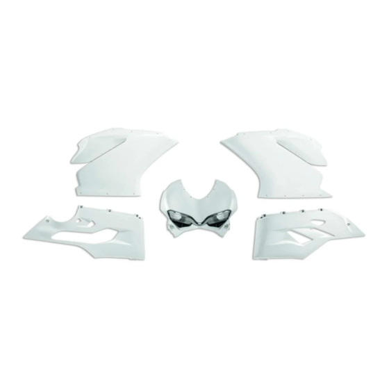
- Seite 122 Superbike 1299 / 1299S ISTR - 692 / 00 97180271A Kit carene/cupolino pista / Racing fairing/headlight fairing kit / Kit carénages/bulle piste / Kit Verkleidung/Cockpitverkleidung Racing / Conjunto de carenagens/cúpula pista / Kit carenados/cúpula pista / サーキット用フェアリング/ヘッドライトフェアリングキット...
- Seite 123 Pos. Cod. Denominazione Description Designation Bezeichnung Descrição Denominacion Q.ty 説明 ヘッドライトフェア 48111181A Cupolino Headlight fairing Bulle Cockpitverkleidung Cúpula Cúpula リング Semicarena Right-hand front Demi-carénage avant Vordere Verkleidungshälfte, Semicarenagem Semicarenado 右フロントフェアリ 48017142A anteriore destra half-fairing droit rechts dianteira direita delantero derecho ング...
- Seite 124 Superbike 1299 / 1299S ISTR - 692 / 00 97180271A Kit carene/cupolino pista / Racing fairing/headlight fairing kit / Kit carénages/bulle piste / Kit Verkleidung/Cockpitverkleidung Racing / Conjunto de carenagens/cúpula pista / Kit carenados/cúpula pista / サーキット用フェアリング/ヘッドライトフェアリングキット...
- Seite 125 Pos. Cod. Denominazione Description Designation Bezeichnung Descrição Denominacion Q.ty 説明 Coperchio 24714331B Conveyor cover Cache du déflecteur Tapa encanalador Tampa conduta Tapa encanalador コンベヤーカバー convogliatore Parafuso de cabeça Tornillo especial TBEI abaulada com Tornillo especial TBEI スクリュー TBEI 77550221A Vite TBEI M4x10 TBEI screw M4x10 Vis TBHC M4x10 M4x10...