
Verwandte Anleitungen für Horizon Hobby HANGAR 9 Ultra Stick 30cc ARF


Inhaltszusammenfassung für Horizon Hobby HANGAR 9 Ultra Stick 30cc ARF
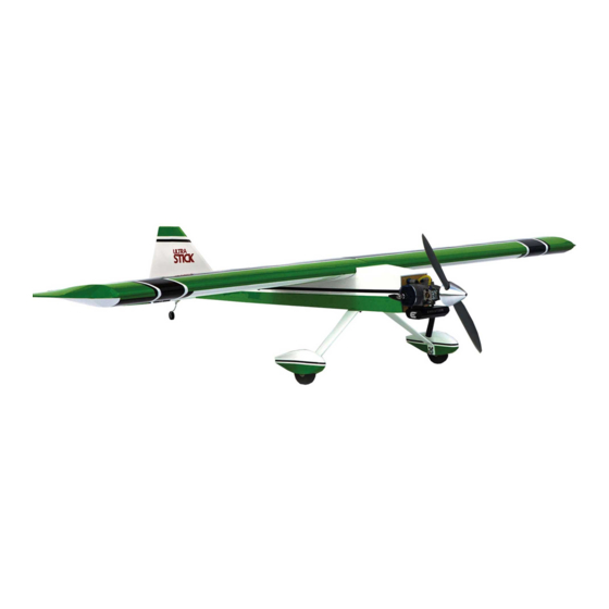
- Seite 1 ™ Ultra Stick 30cc Instruction Manual Bedienungsanleitung Manuel d’utilisation Manuale di Istruzioni...
- Seite 2 SPECIFICATIONS • SPEZIFIKATIONEN • SPÉCIFICATIONS • SPECIFICHE LARGE PARTS LAYOUT • BAUTEILE (OHNE KLEINTEILE) • GRANDES PIÈCES • SCHEMA DEI COMPONENTI GRANDI 81.0 in (206 cm) 1360 sq in (87.8 dm2) Total/Totale 73 in (185 cm) 12–14 lbs (5.4–6.35 kg) 2-Stroke Gas: 30cc, 4-Stroke gas/petrol: 36cc 2-Takt Benziner: 30cc, 4-Takt Benzin: 36 cc 2 temps Essence: 30cc, 4 temps essence: 36cc...
- Seite 3 Part # English Deutsch Français Italiano REPLACEMENT PARTS • ERSATZTEILE • PIÈCES DE RECHANGE • PEZZI DI RICAMBIO HAN236501 Fuselage Rumpf Fuselage Fusoliera HAN236502 Left Wing with Aileron and Flap Tragfl äche Links mit Querruder und Klappe Aile gauche avec aileron et volet Semiala sinistra con alettone e fl...
- Seite 4 Part # English Deutsch Français Italiano REQUIRED RADIO EQUIPMENT • ERFORDERLICHE RC AUSRÜSTUNG • ÉQUIPEMENT RADIO REQUIS • APPARECCHIATURE RADIO NECESSARIE ® SPMAR9350 Spektrum AR9350 9-Kanal AS3X-Empfänger Récepteur AR9350 9 voies AS3X Ricevente AR9350 9-canali AS3X AR9350 9-Channel AS3X Receiver SPMB2000LPRX 2000mAh 2S 7.4V LiPo Receiver Battery...
- Seite 5 Part # English Deutsch Français Italiano REQUIRED ADHESIVES • ERFORDERLICHE KLEBSTOFFE • TYPES DE COLLES • ADESIVI NECESSARI DLMAD44 Roket Rapid CA 5-10 sec: 20g Roket Rapid CA 5-10 s: 20 g Colle cyano Roket Rapid 5-10 sec: 20g Colla cianoacrilica Roket Rapid 5-10 sec: 20 g DLMAD45 Roket Max CA 10-20 sec: 20g Roket Max CA 10-20 s: 20 g...
-
Seite 6: Before Starting Assembly
Horizon Hobby, LLC. This manual contains instructions for safety, operation and maintenance. It is essential to read and follow all the instructions and warnings in the manual, prior to assembly, setup or use, in order to operate •... -
Seite 7: Vor Dem Zusammenbau
Halten Sie lose Gegenstände die sich im Propeller verfangen können weg vom Propeller. Dieses gilt auch für Kleidung Alle Anweisungen, Garantien und anderen zugehörigen Dokumente können im eigenen Ermessen von Horizon Hobby, oder andere Objekte wie zum Beispiel Stifte oder Schraubendreher. -
Seite 8: Avant De Commencer L'assemblage
être utilisé par des enfants sans la surveillance directe d’un adulte. N’essayez pas de modifi er ou d’utiliser ce produit avec des composants incompatibles hors des instructions fournies par Horizon Hobby, LLC. Ce manuel comporte des Si l’entoilage présente quelque plis, vous pouvez les lisser en utilisant le pistolet à air chaud (HAN100) et le gant instructions relatives à... - Seite 9 • Se si trovano parti danneggiate, contattare il negozio da cui è stato acquistato. o alterare il prodotto in nessuna maniera al di fuori delle istruzioni fornite da Horizon Hobby, LLC. Questo manuale contiene le istruzioni per un funzionamento e una manutenzione sicuri. È fondamentale leggere e seguire tutte le Se si trovano delle pieghe nella ricopertura, si possono togliere usando una pistola ad aria calda (HAN100) e guanto per istruzioni e le avvertenze del manuale prima di montare, confi...
- Seite 10 BUILDING PRECAUTIONS HINWEISE ZUM BAU PRÉCAUTIONS D’ASSEMBLAGE PRECAUZIONI PER LA COSTRUZIONE During assembly, we recommend resting the parts on a Während des Zusammenbaus empfehlen wird, dass die Lors de l’assemblage de votre modèle, nous vous Durante l’assemblaggio noi consigliamo di appoggiare soft surface such as a soft towel to help prevent denting Teile auf einer weichen Oberfl...
- Seite 11 AILERON AND FLAP INSTALLATION Use side cutters to trim the screws. Use a 1/16-inch (1.5mm) drill bit to clear the holes of any debris for the control horn mounting screws. Puncture the covering so the control horn backing plate Use a fi...
- Seite 12 11. Repeat the previous steps to install all four of the aileron 16. Check the gap between the fl ap and aileron. Use a thin hinges. ruler (or similar) as a spacer so the gap between the left and right ailerons and fl aps are the same. Glue the hinges for the fl...
- Seite 13 Thread an M3 x 15 self-tapping screw into each of the 10. Secure the servo to the cover using a 2mm hex wrench holes in the aileron and fl ap servo cover mounting holes. and the screws provided with the servo. Remove the screws before proceeding.
-
Seite 14: Wing Installation
15. Secure the aileron cover in the wing using four M3 x 15 20. Use the radio system to set the fl ap to the up position. self-tapping screws. Use the radio to center the fl ap into the neutral position. 16. - Seite 15 Place the wing bolt plate on the wing, then thread the Use a ruler and carefully cut the covering 1/8 inch (3 1/4-20 x 13/4-inch nylon wing bolts into the blind nuts in mm) inside the line drawn on the stabilizer to remove the fuselage to secure the wing.
- Seite 16 10. Use clamps to hold the stabilizer in position. Allow the Use a ruler and carefully cut the covering 1/8 inch (3 epoxy to fully cure before proceeding. mm) below the line drawn on the fi n. Remove the bottom covering.
- Seite 17 Drill a 1/16-inch (1.5mm) hole in the center of each Mix a small amount of 15-minute epoxy. Use a toothpick hinge slot for in both the elevator and stabilizer. Prepare to apply epoxy to the rudder where the tail wheel wire and install the elevator hinges, then fi...
-
Seite 18: Radio Installation
RADIO INSTALLATION Prepare the hinge slots and hinges for the rudder. Install the hinges and fi t the rudder to the fi n. Align the top of Prepare the rudder and elevator servos by installing the the fi n and rudder. Use thin CA to glue the hinges. Once rubber grommets and brass eyelets. - Seite 19 Mount the receiver battery in the fuselage using hook 10. Thread a nylon ball end on the 35 -inch (900mm) and loop tape. Make a brace from mixing sticks to keep elevator pushrod, then snap the ball into the ball end. the battery secure in the fuselage.
-
Seite 20: Landing Gear Installation
15. Assemble the elevator linkages following the same Place a drop of light machine oil on the axle, then slide procedure as the aileron and fl ap linkages using the the wheel on the axle. Position the wheel collar fl ush with -inch (235mm) pushrod. -
Seite 21: Electric Motor Installation
Attach the wheel pants to the landing gear using two M3 Trim the covering inside the opening at the rear of the x 10 button head screws and two M3 washers. Apply hatch. Use a covering iron to seal the covering into the thread lock on the screws, then tighten them using a opening. -
Seite 22: Gas Engine Installation
10. Secure the speed controller inside the fuselage. Make 15. Place the hatch back into position on the fuselage. The any connections to the motor, and for the battery, before magnets will hold the hatch securely under normal proceeding. fl ying conditions. In extreme fl ight, it is recommended to secure the hatch using an M3 x 10 mm socket head cap screw and M3 washer. - Seite 23 Use a drill and 3/16-inch (5mm) drill bit to enlarge the Center the throttle stick and trim. Place the servo arm on holes to mount the engine. Enlarge the hole for the the throttle servo perpendicular to the servo centerline. throttle pushrod using a drill and 9/64-inch (3.5mm) drill Remove any arms that will not be used from the servo bit.
- Seite 24 12. Use side cutters to trim the pushrod tube at the front 17. Fit the spinner backplate to the motor. It may be edge of the servo tray. necessary to enlarge the hole in the backplate or use the included adapters to fi t the propeller shaft. 13.
- Seite 25 Bend the vent and fi ll lines as shown. Install the fuel fi lter in the line to the carburetor. The fuel line can then be secured to the carburetor. A clunk can also be attached to the fill line, which will allow better removal of the fuel after a flying session.
-
Seite 26: Center Of Gravity
CENTER OF GRAVITY CONTROL THROWS An important part of preparing the aircraft for fl ight is properly balancing the model. Turn on the transmitter and receiver of your model. Check the movement of the rudder using the transmitter. When the stick is moved to the right, the rudder should also move right. -
Seite 27: Preflight Checklist
INCIDENTAL OR CONSEQUENTIAL DAMAGES, LOSS OF your airplane. Use the recommended charger supplied Do not fl y below the manufacturer’s recommended Horizon Hobby, LLC, (Horizon) warrants to the original PROFITS OR PRODUCTION OR COMMERCIAL LOSS IN ANY with your radio system. Follow the instructions voltage. -
Seite 28: Warranty And Service Contact Information
Germany 25337 Elmshorn, When calling Horizon, you will be asked to provide your return freight. Horizon accepts money orders and Sales: Horizon Hobby GmbH +49 (0) 4121 2655 100 Germany complete name, street address, email address and phone cashier’s checks, as well as Visa, MasterCard, American number where you can be reached during business infofrance@horizonhobby.com... - Seite 29 MONTAGE VON QUERRUDER UND KLAPPE Mit einem Seitenschneider die Schrauben trimmen. Mit einem 1,5 mm (1/16 Zoll) Bohrer die Löcher von Schmutzrückständen durch die Befestigungsschrauben des Steuerhorns befreien. Die Abdeckung punktieren, sodass die Montageplatte des Mit einer Feile vorsichtig alle scharfen Kanten von Steuerhorns für die Schrauben erreichbar ist.
- Seite 30 11. Die vorherigen Schritte zur Montage der vier 16. Den Spalt zwischen Klappe und Querruder prüfen. Aufhängungen des Querruders wiederholen. Ein dünnes Lineal (oder ähnliches) als Abstandhalter verwenden, sodass beim linken und rechten Querruder und den Klappen der Spalt die gleiche Größe hat. Die Aufhängungen für die Klappen mit dünnem CA-Klebstoff kleben.
- Seite 31 Eine M3 x 15 Blechschraube in jedes Loch der Halterung 10. Den Servo auf der Abdeckung mit einem 2 mm der Servoabdeckung von Querruder und Klappe Sechskant und den mit dem Servo bereitgestellten einführen. Die Schrauben vor dem Fortfahren entfernen. Schrauben sichern. Eine kleine Menge dünnen CA-Klebstoff zum Härten der 11.
-
Seite 32: Montage Der Flügel
15. Die Abdeckungen des Querruders im Flügel mit vier M3 x 20. Mit dem Funksystem die Klappen in die Aufwärtsposition 15 Blechschrauben sichern. bringen. Mit dem Funksystem die Klappen in der Neutralposition zentrieren. 16. Eine M3 Mutter auf das eine Ende des 100 mm Gestänge 21. - Seite 33 Die Flügelschraubenplatte des Flügels auf den Flügel Ein Lineal verwenden und die Abdeckung 3 mm platzieren, dann die 1/4-20 x 330 mm (13/4 Zoll) (1/8 Zoll) innerhalb der gezogenen Linie auf dem Nylon-Flügelschrauben in die Blindmuttern im Rumpf Stabilisator schneiden, um die Abdeckung im der Mitte schrauben, um den Flügel zu sichern.
-
Seite 34: Montage Des Höhenruders
10. Mit den Klemmen den Stabilisator in Position halten. Das Ein Lineal verwenden und vorsichtig die Abdeckung Epoxid muss vor dem Fortfahren vollständig ausgehärtet 3 mm (1/8 Zoll) unter der gezogenen Linie auf dem sein. Seitenleitwerk entfernen. Die untere Abdeckung entfernen. Vorsicht walten lassen, um nicht in das darunterliegende Holz zu schneiden, was zur Schwächung des Seitenleitwerks führt. - Seite 35 Ein 1,5 mm (1/16 Zoll) Loch in die Mitte eines jeden Eine kleine Menge des 15-minütigen Epoxids mischen. Schlitzes der Aufhängung für Höhenruder und Stabilisator Mit einem Zahnstocher Epoxid auf das Seitenruder bohren. Die Höhenruderaufhängungen vorbereiten und auftragen, wo das Kabel des Spornrads das freigelegte montieren, dann das Höhenruder auf den Stabilisator Holz berührt.
-
Seite 36: Montage Des Funkgeräts
MONTAGE DES FUNKGERÄTS Die Schlitze für die Aufhängungen und die Aufhängungen für das Seitenruder vorbereiten. Die Aufhängungen Die Servos von Seitenruder und Querruder durch montieren und das Seitenruder in das Seitenleitwerk die Montage der Gummihülsen und Messingösen einpassen. Die Oberseite von Seitenleitwerk und vorbereiten. - Seite 37 Den Empfänger-Akku im Rumpf mit Klettband montieren. 10. Ein Nylon-Gelenkkopfende auf das 900 mm (35 Eine Halterung aus Stäben erschaffen, um den Akku im Zoll) Gestänge des Höhenruders schrauben, dann die Rumpf sicher zu halten. Kugel in das Gelenkkopfende einrasten. Eine 3 mm Unterlegscheibe auf eine M3 x 12 Zylinderkopfschrauben schieben, dann die Schraube in das Außenloch des ...
-
Seite 38: Montage Des Fahrwerks
15. Das Gestänge des Höhenruders entsprechend demselben Einen Tropfen leichtes Maschinenöl auf die Achse Verfahren wie für die Gestänge von Querruder und auftragen, dann das Rad auf die Achse schieben. Klappen mit einem 235 mm (9 Zoll) Gestänge Die Anschlaghülse mit dem Ende der Achse bündig zusammenbauen. -
Seite 39: Montage Des Elektromotors
Die Radverkleidung mit zwei M3 x 10 Die Abdeckung in der Öffnung am hinteren Teil der Rundkopfschrauben und zwei M3 Unterlegscheiben Abdeckung trimmen. Mit einem Heißsiegelgerät die am Fahrwerk anbringen. Gewindesicherung auf die Abdeckung in der Öffnung versiegeln. Die Öffnung wird Schrauben auftragen, dann einem 2 mm Sechskant zum Entfernen der Abdeckung verwendet, um Zugang zu festziehen. - Seite 40 10. Den Geschwindigkeitsregler im Rumpf sichern. Vor dem 15. Die Abdeckung wieder in Position auf dem Rumpf Fortfahren sämtliche Verbindungen zum Motor und für positionieren. Die Magneten werden die Abdeckung die Akkus herstellen. unter normalen Flugbedingungen sicher halten. Bei einem Extremfl ug wird empfohlen, die Abdeckung mit einer M3 x 10 mm Zylinderkopfschraube und einer M3 Unterlegscheibe zu sichern.
- Seite 41 Mit einem 5 mm (3/16 Zoll) Bohrer die Löcher für die Den Gashebel zentrieren und trimmen. Den Servoarm am Montage des Motors vergrößern. Das Loch für das Gasservo senkrecht zur Mittellinie des Servos platzieren. Gasgestänge mit einem 3,5 mm (9/64 Zoll) Bohrer Alle Arme entfernen, die nicht vom Servoarm aus vergrößern.
- Seite 42 12. Mit einem Seitenschneider das Gestängerohr an der 17. Die Spinnerrückplatte am Motor einpassen. Es kann Vorderkante der Akku-Halterung trimmen. notwendig sein, das Loch in der Rückplatte zu vergrößern oder den mitgelieferten Adapter zu verwenden, damit die Propellerwelle passt. 13. Einen Gabelkopfhalter (Silikonrohr) über den Nylon- 18.
- Seite 43 Die Entlüftung und die Füllleitungen entsprechend der Die Kraftstoffl eitung in der Leitung zum Vergaser Abbildung biegen. montieren. Die Kraftstoffl eitung kann dann am Vergaser gesichert werden. Ein Pendel kann auch an der Füllleitung angebracht werden, wodurch der Kraftstoff nach einem Flug besser abgeleitet werden kann.
-
Seite 44: Der Schwerpunkt
DER SCHWERPUNKT RUDERAUSSCHLAG Ein wichtiger Teil bei der Vorbereitung des Flugzeugs für den Flug ist das ordnungsgemäße Ausbalancieren des Den Sender und Empfänger des Modells einschalten. Die Bewegung des Seitenruders mit der Fernsteuerung Modells. prüfen. Wird der Steuerhebel nach rechts bewegt, sollte sich auch das Seitenruder nach rechts bewegen. Die Richtung auf dem Servo am Empfänger bei Bedarf umkehren. -
Seite 45: Täglicher Flug Check
• Prüfen Sie den RC Einbau und stellen sicher dass alle vernünftig gesichert sind. Exklusive Garantie Horizon Hobby LLC (Horizon) Ausgeschlossen sind auch Fälle die bedingt durch (vii) Ruderfunktionen (Quer-, Höhen-, Seitenruder) und • Stellen Sie sicher, dass sich alle Ruder in die richtige... -
Seite 46: Garantie Und Service Kontaktinformationen
Sie sich entweder an Ihren Fachhändler oder direkt an das Produkt repariert oder ersetzt. Diese Entscheidung Hinweise für die Wartung und den Betrieb des Produktes. Horizon. obliegt einzig Horizon Hobby. Es ist unabdingbar, diese Hinweise vor der ersten Rücksendungen / Reparaturen werden nur mit einer Kostenpfl ichtige Reparaturen Inbetriebnahme zu lesen und zu verstehen. - Seite 47 INSTALLATION DES AILERONS ET VOLETS Utilisez une pince coupante pour couper les vis. Utilisez un foret de 1,5mm pour retirer les débris des trous destinés à la fi xation des guignols. Percez l'entoilage afi n que les vis puissent atteindre la Utilisez une lime pour limer légèrement les pointes plaque de renfort des guignols.
- Seite 48 11. Répétez les étapes précédentes pour installer les quatre 16. Vérifi ez l'espace entre le volet et l'aileron. Utilisez une charnières d'ailerons. règle fi ne (ou similaire) comme outil d'espacement afi n d'obtenir le même espace entre les ailerons et les volets droit et gauche.
- Seite 49 Vissez une vis auto-taraudeuse M3 x 15 dans chaque 10. Fixez le servo sur la trappe à l'aide d'un clé à écrou 2mm trou de fi xation de la trappe de servo aileron et volet. et les vis fournies avec le servo. Retirez les vis avant de continuer.
- Seite 50 15. Fixez la trappe aileron sur l'aile à l'aide de quatre vis 20. Utilisez l'émetteur pour régler le volet en position haute. auto-taraudeuses M3 x 15. Utilisez l'émetteur pour régler le volet au neutre. 16. Vissez un écrou M3 à l'extrémité de la tringlerie de 21.
-
Seite 51: Installation Du Stabilisateur
Mettez la plaque de fi xation sur l'aile puis vissez les vis à A l'aide d'une règle, coupez soigneusement l'entoilage papillon 1/4-20 x 13/4" en nylon dans les écrous borgne à 3mm à l'intérieur de la ligne tracée sur le stabilisateur du fuselage pour fi... -
Seite 52: Installation De La Dérive
10. Utilisez des serre-joints pour maintenir le stabilisateur A l'aide d'une règle, coupez soigneusement l'entoilage à en place. Laissez l'époxy sécher complètement avant de 3mm sous la ligne tracée sur la dérive. Retirez l'entoilage continuer. en dessous. Faites attention de ne pas couper le bois subjacent, cela affaiblirait la dérive. - Seite 53 Percez un trou de 1,5mm au centre de chaque rainure Mélangez un peu de colle époxy 15 minutes. Utilisez de charnière sur la profondeur et le stabilisateur. un cure-dent pour appliquer de l’époxy sur la dérive à Préparez et installez les charnières de profondeur puis l'endroit où...
- Seite 54 INSTALLATION RADIO Préparez les rainures de charnière et les charnières pour la dérive. Installez les charnières et installez la partie Préparez les servos de dérive et de profondeur en mobile de la dérive sur la partie fi xe. Alignez le haut des installant les silent-blocs en caoutchouc.
- Seite 55 Installez la batterie récepteur dans le fuselage à l'aide 10. Vissez une chape à boule en nylon sur la tringlerie de de bande auto-agrippante. Faites une cale avec le bâton profondeur de 900mm puis insérez la boule dans la mélangeur pour maintenir la batterie dans le fuselage. chape.
-
Seite 56: Installation Du Train D'atterrissage
15. Assemblez la tringlerie de profondeur en suivant la Mettez une goutte de lubrifi ant sur l'axe puis glissez la même procédure que les tringleries d'ailerons et de roue sur l'axe. Mettez la bague d'arrêt de roue contre volets à l'aide de la tringlerie de 235mm. Attachez la l'extrémité... -
Seite 57: Installation Du Moteur Électrique
Fixez les carénages de roue sur le train d'atterrissage Coupez l'entoilage à l'intérieur de l'ouverture à l'arrière à l'aide de deux vis à tête bombée M3 x 10 et deux de la trappe. Utilisez un fer à entoiler pour fi xer rondelles M3. - Seite 58 10. Fixez le contrôleur de vitesse dans le fuselage. Faites 15. Remettez la trappe en place sur le fuselage. Les aimants toutes les connections moteur et batterie avant de maintiendront la trappe en place en conditions normales continuer. de vol. En vol extrême, il est recommandé de fi xer la trappe à...
- Seite 59 Utilisez une mini-perceuse et un foret de 5mm pour Mettez le manche et le trim des gaz au neutre. Placez le élargir les trous pour l'installation du moteur. Élargissez palonnier sur le servo des gaz perpendiculairement à la le trou de la tringlerie des gaz à l'aide d'une mini- ligne centrale du servo.
- Seite 60 12. Utilisez une pince coupante pour couper la gaine de 17. Installez le fl asque arrière du cône sur le moteur. Vous tringlerie au niveau de l'arrête avant du servo. devrez peut-être élargir le trou du fl asque ou utiliser les adaptateurs fournis pour qu'il soit adapté...
- Seite 61 Pliez le tube de mise à l'air et de remplissage comme sur Installez le fi ltre à carburant sur la durite du carburateur. la photo. La durite carburant peut alors être reliée au carburateur. Un plongeur peut être relié à la durite de remplissage, ce qui permettra de simplifier la vidange du carburant après le vol.
-
Seite 62: Centre De Gravité
CENTRE DE GRAVITÉ DÉBATTEMENTS Une des étapes importantes de la préparation d’un modèle est son équilibrage. Mettez l’émetteur et le récepteur sous tension. Contrôlez les mouvements de la dérive en utilisant votre émetteur. Quand le manche est vers la droite, la dérive doit s’orienter vers la droite. Inversez la direction du servo à Fixez les ailes au fuselage. -
Seite 63: Checklist D'avant Vol
Utilisez le chargeur fourni avec votre Ne volez jamais en dessous de la tension minimale Garantie exclusive - Horizon Hobby, LLC (Horizon) garantit de revenus ou de pertes commerciales, liés de quelque radio. Suivez les instructions fournies avec votre recommandée par le fabricant. -
Seite 64: Coordonnées De Garantie Et Réparations
Cette coûteuses et doivent par conséquent être effectuées revendeur qui conviendra avec Horizon d’une décision décision relève uniquement d’Horizon Hobby. par l’acheteur lui-même. appropriée, destinée à vous aider le plus rapidement Réparations payantes... - Seite 65 INSTALLAZIONE ALETTONE E FLAP Usare tronchesi taglienti per rifi lare le viti. Usare un trapano con punta da 1,5 mm per rimuovere eventuali detriti dai fori per le viti di montaggio delle squadrette. Forare la copertura in modo che le viti entrino nella Usare una lima per rimuovere leggermente eventuali piastra di supporto delle squadrette.
- Seite 66 11. Ripetere i passi precedenti per installare le quattro 16. Controllare lo spazio vuoto tra il fl ap e l'alettone. Usare cerniere dell'alettone. un righello sottile (o simili) come distanziatore in modo che lo spazio vuoto tra i fl ap e gli alettoni destri e sinistri sia identico.
- Seite 67 Avvitare una vite autofi lettante M3 x 15 in ognuno dei 10. Fissare il servo alla copertura usando una chiave fori nella copertura del servo dell'alettone e del fl ap. esagonale da 2 mm e le viti fornite in dotazione con il Rimuovere le viti prima di procedere.
-
Seite 68: Installazione Dell'ala
15. Fissare la copertura dell'alettone nell'ala usando quattro 20. Usare la radio per sollevare il fl ap. Usare la radio per viti autofi lettanti M3 x 15. posizionare il fl ap al centro (posizione neutra). 16. Avvitare un dado M3 a un'estremità dell'asta di comando 21. - Seite 69 Posizionare la piastrina per i bulloni sull'ala, quindi Usare un righello e tagliare attentamente la copertura 3 avvitare i bulloni di plastica da 1/4-20 x 13/4 pollici nei mm all'interno della linea tracciata sullo stabilizzatore dadi ciechi nella fusoliera per fi ssare l'ala. per rimuovere la copertura dal centro dello stesso.
- Seite 70 10. Usare delle morse per tenere fermo lo stabilizzatore. Usare un righello e tagliare attentamente la copertura Lasciare asciugare la colla prima di procedere. 3 mm sotto la linea tracciata sulla pinna. Rimuovere la copertura inferiore. Fare attenzione a non tagliare il legno sottostante, indebolendo la pinna.
- Seite 71 Praticare un foro di 1,5 mm al centro di ogni scanalatura Miscelare una piccola quantità di colla epossidica 15 per l'elevatore e lo stabilizzatore. Preparare e installare minuti. Usare uno stuzzicadenti per applicare la colla le cerniere dell'elevatore, quindi fi ssare l'elevatore allo epossidica sul direzionale nel punto in cui il cavetto stabilizzatore.
-
Seite 72: Installazione Della Radio
INSTALLAZIONE DELLA RADIO Preparare le scanalature e le cerniere per il direzionale. Installare le cerniere e fi ssare il direzionale alla Preparare i servi del direzionale e dell'elevatore pinna. Allineare la parte sommitale della pinna con il installando i gommini e gli occhielli di ottone. Installare i direzionale. - Seite 73 Montare la batteria della ricevente nella fusoliera usando 10. Avvitare una testa a snodo di plastica sull'asta di nastro a strappo. Ricavare un rinforzo per tenere ferma la comando dell'elevatore lunga 900 mm, quindi inserire batteria nella fusoliera. l'uniball nella testa a snodo. Inserire una rondella di 3 mm su una vite a brugola M3 x 12, quindi avvitare la vite nel foro esterno della squadretta del servo dell'elevatore.
- Seite 74 15. Assemblare i rinvii dell'elevatore seguendo la stessa Mettere una goccia di olio leggero per macchine procedura usata per i rinvii dell'alettone e del fl ap usando sull'asse, quindi inserire il ruotino sull'asse. Posizionare l'asta di comando lunga 235 mm. Fissare la testa a il collarino a fi...
- Seite 75 Fissare le scarpette copriruote al carrello usando due Sistemare la copertura all'interno dell'apertura nella viti a testa tonda M3 x 10 e due rondelle M3. Applicare il parte posteriore dello sportello. Usare un ferro da stiro frenafi letti sulle viti, quindi stringerle usando una chiave per sigillare la copertura nell'apertura.
- Seite 76 10. Fissare il regolatore all'interno della fusoliera. Prima di 15. Rimontare lo sportello sulla fusoliera. I magneti terranno procedere, eseguire eventuali collegamenti al motore e lo sportello saldamente in posizione in condizioni di volo per la batteria. normali. In condizioni estreme si consiglia di fi ssare lo sportello usando una vite a brugola M3 x 10 mm e una rondella M3.
- Seite 77 Usare un trapano con punta da 5 mm per allargare i Centrare lo stick e il trim del gas. Montare la squadretta fori per il montaggio del motore. Allargare il foro per del servo sul servo del gas in posizione perpendicolare l'asta di comando del gas usando un trapano con alla linea centrale del servo.
- Seite 78 12. Usare tronchesi taglienti per rifi lare il tubo dell'asta di 17. Fissare il fondello dell'ogiva al motore. Potrebbe essere comando sul bordo anteriore del supporto del servo. necessario allargare il foro sul fondello o usare gli adattatori inclusi per fi ssare l'albero dell'elica. 13.
- Seite 79 Curvare il tubo di sfi ato e quello di riempimento come Installare il fi ltro carburante nel tubo collegato al mostrato nella fi gura. carburatore. Il tubo carburante può quindi essere fi ssato al carburatore. Al tubo del carburante può essere fissato un filtro a pendolino che consente di rimuovere più...
-
Seite 80: Corse Dei Comandi
BARICENTRO CORSE DEI COMANDI Una parte molto importante nella preparazione del modello riguarda il suo bilanciamento. Accendere trasmittente e ricevente del modello. Verifi care il movimento del timone agendo sulla trasmittente. Quando si sposta lo stick verso destra il timone deve andare a destra. Se necessario, invertire la direzione del Fissare le ali alla fusoliera. -
Seite 81: Lista Dei Controlli Prima Del Volo
Non volare se la tensione è inferiore a quella indicata Garanzia esclusiva - Horizon Hobby, LLC (Horizon) non idonei a cura di soggetti diversi da Horizon. La consigliati o forniti con il radiocomando e seguendo dal costruttore;... -
Seite 82: Contatti Per La Garanzia E L'assistenza
Horizon per prendere una decisione che vi Questa decisione spetta esclusivamente a Horizon Hobby. 10/15 possa aiutare nel più breve tempo possibile. Riparazioni a pagamento... - Seite 83 Ultra Stick ™ 30cc...
- Seite 84 © 2016 Horizon Hobby, LLC. Hangar 9, Ultra Stick, Evolution, DSM, DSMX, PowerSafe, X-Plus, AS3X and the Horizon Hobby logo are trademarks or registered trademarks of Horizon Hobby, LLC. The Spektrum trademark is used with permission of Bachmann Industries, Inc.