Inhaltsverzeichnis
Werbung
Verfügbare Sprachen
Verfügbare Sprachen
ACOPOSinverter P74
ACOPOSinverter P74New
Anwenderhandbuch
Version: 2.60 (Dezember 2018)
Bestellnr.: MAACPIP74-GER
Übersetzung der Originalbetriebsanleitung
Alle Angaben entsprechen dem aktuellen Stand zum Zeitpunkt der Erstellung des Handbuches. Inhaltliche
Änderungen dieses Handbuches behalten wir uns ohne Ankündigung vor. Die B&R Industrial Automation GmbH
haftet nicht für technische oder redaktionelle Fehler und Mängel in diesem Handbuch. Außerdem übernimmt die
B&R Industrial Automation GmbH keine Haftung für Schäden, die direkt oder indirekt auf Lieferung, Leistung und
Nutzung dieses Materials zurückzuführen sind. Wir weisen darauf hin, dass die in diesem Dokument verwendeten
Soft- und Hardwarebezeichnungen und Markennamen der jeweiligen Firmen dem allgemeinen warenzeichen-,
marken- oder patentrechtlichen Schutz unterliegen.
Werbung
Inhaltsverzeichnis

Inhaltszusammenfassung für B&R Industries ACOPOSinverter P74-Serie
- Seite 1 ACOPOSinverter P74 ACOPOSinverter P74New Anwenderhandbuch Version: 2.60 (Dezember 2018) Bestellnr.: MAACPIP74-GER Übersetzung der Originalbetriebsanleitung Alle Angaben entsprechen dem aktuellen Stand zum Zeitpunkt der Erstellung des Handbuches. Inhaltliche Änderungen dieses Handbuches behalten wir uns ohne Ankündigung vor. Die B&R Industrial Automation GmbH haftet nicht für technische oder redaktionelle Fehler und Mängel in diesem Handbuch.
-
Seite 3: Inhaltsverzeichnis
Inhaltsverzeichnis 1 ACOPOSinverter P74....................7 1.1 Geräteüberblick............................... 7 1.2 Bestellnummernschlüssel..........................8 1.3 Bestelldaten..............................9 1.3.1 8I74S200018.01P-1, 8I74S200037.01P-1, 8I74S200055.01P-1, 8I74S200018.00-000, 8I74S200037.00-000, 8I74S200055.00-000.......................9 1.3.2 8I74S200075.01P-1, 8I74S200110.01P-1, 8I74S200150.01P-1, 8I74S200220.01P-1, 8I74S200075.00-000, 8I74S200110.00-000, 8I74S200150.00-000, 8I74S200220.00-000......10 1.3.3 8I74T400037.01P-1, 8I74T400055.01P-1, 8I74T400075.01P-1, 8I74T400110.01P-1, 8I74T400037.00-000, 8I74T400055.00-000, 8I74T400075.00-000, 8I74T400110.00-000.......11 1.3.4 8I74T400150.01P-1, 8I74T400220.01P-1, 8I74T400300.01P-1, 8I74T400400.01P-1, 8I74T400150.00-000, 8I74T400220.00-000, 8I74T400300.00-000, 8I74T400400.00-000...... - Seite 4 Inhaltsverzeichnis 2.9 Wartung................................. 82 2.10 Netzkurzschlusskapazität und Kurzschlussschutz..................83 2.11 Common DC bus............................84 2.11.1 Introduction.............................84 2.11.2 Before you begin - Safety information....................84 2.11.2.1 Basic information..........................84 2.11.2.2 Voltage measurement at the DC bus....................85 2.11.2.3 Standards and terminology......................85 2.11.3 Technical data............................86 2.11.3.1 Drive amplifier data..........................
- Seite 5 Inhaltsverzeichnis 3.2.2.3 Menu..............................142 3.2.3 Configuration Mode (ConF)........................169 3.2.3.1 Introduction............................169 3.2.3.2 Organization tree..........................170 3.2.3.3 My Menu............................171 3.2.3.4 Factory Settings..........................171 3.2.3.5 Macro Configuration.........................172 3.2.3.6 Full..............................174 3.2.4 Interface (ItF)............................360 3.2.4.1 Access Level (LAC)......................... 360 3.2.4.2 Language (LnG)..........................362 3.2.4.3 Monitoring Configuration (MCF).......................363 3.2.4.4 Display configuration (dCF)......................
- Seite 6 Inhaltsverzeichnis 4.6.10 Sicherheit gemäß IEC 61508 und IEC 60204-1 - Fall 2..............429 4.7 Inbetriebnahme............................430 4.7.1 Registerkarte "Sicherheitsfunktionen"....................430 4.7.2 Fenster "Sicherheitsfunktionen konfigurieren"..................431 4.7.3 Visualisierung und Status der Sicherheitsfunktionen................435 4.7.4 Sicherheitsbezogene Konfiguration von Gerät auf PC und umgekehrt kopieren........436 4.7.5 Maschinensignatur..........................440 4.8 Installation..............................
-
Seite 7: Acoposinverter P74
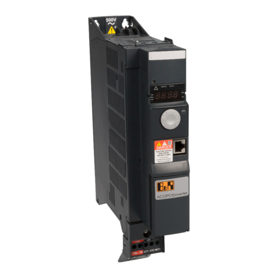
ACOPOSinverter P74 1 ACOPOSinverter P74 1.1 Geräteüberblick Die Produktfamilie ACOPOSinverter P74 umfasst vier Umrichterbaugrößen (A, B, C und D) und ist ideal geeignet für die Einbindung kompakter, leistungsstarker Umrichterlösungen mit einer hohen Leistungsanforderung. Vier Baugrößen Baugröße A Baugröße B 8I74S200018.01P-1, 8I74S200037.01P-1, 8I74S200055.01P-1, 8I74S200110.01P-1, 8I74S200150.01P-1, 8I74S200220.01P-1, 8I74S200075.01P-1, 8I74T400037.01P-1, 8I74T400055.01P-1, 8I74T400220.01P-1, 8I74T400300.01P-1, 8I74T400400.01P-1,... -
Seite 8: Bestellnummernschlüssel
ACOPOSinverter P74 1.2 Bestellnummernschlüssel Produktbereich Gruppe Motion Produktfamilie ACOPOSinverter Bauserie ACOPOSinverter P74 & P74New Phasenzahl 1-phasig 3-phasig Spannungsbereich 200 bis 240 V 380 bis 500 V Nennleistung W x 10 W x 10 W x 10 W x 10 W x 10 Schinttstelle ACOPOSinverter P74 POWERLINK ACOPOSinverter P74... -
Seite 9: Bestelldaten
ACOPOSinverter P74 1.3 Bestelldaten 1.3.1 8I74S200018.01P-1, 8I74S200037.01P-1, 8I74S200055.01P-1, 8I74S200018.00-000, 8I74S200037.00-000, 8I74S200055.00-000 Bestellnummer Kurzbeschreibung Abbildung ACOPOSinverter P74 - 1-phasig 200 bis 240 V 8I74S200018.01P-1 ACOPOSinverter P74, 1x 200 bis 240 V, 0,18 kW, EMV Fil- ter und Bremschopper integriert, Schirmblech im Lieferumfang, POWERLINK Interface 8I74S200037.01P-1 ACOPOSinverter P74, 1x 200 bis 240 V, 0,37 kW, EMV Fil-... -
Seite 10: 8I74S200220.01P
ACOPOSinverter P74 1.3.2 8I74S200075.01P-1, 8I74S200110.01P-1, 8I74S200150.01P-1, 8I74S200220.01P-1, 8I74S200075.00-000, 8I74S200110.00-000, 8I74S200150.00-000, 8I74S200220.00-000 Bestellnummer Kurzbeschreibung Abbildung ACOPOSinverter P74 - 1-phasig 200 bis 240 V 8I74S200075.01P-1 ACOPOSinverter P74, 1x 200 bis 240 V, 0,75 kW, EMV Fil- ter und Bremschopper integriert, Schirmblech im Lieferumfang, POWERLINK Interface 8I74S200110.01P-1 ACOPOSinverter P74, 1x 200 bis 240 V, 1,1 kW, EMV Fil-... -
Seite 11: 8I74T400110.01P
ACOPOSinverter P74 1.3.3 8I74T400037.01P-1, 8I74T400055.01P-1, 8I74T400075.01P-1, 8I74T400110.01P-1, 8I74T400037.00-000, 8I74T400055.00-000, 8I74T400075.00-000, 8I74T400110.00-000 Bestellnummer Kurzbeschreibung Abbildung ACOPOSinverter P74 - 3-phasig 380 bis 500 V 8I74T400037.01P-1 ACOPOSinverter P74, 3x 380 bis 500 V, 0,37 kW, EMV Fil- ter und Bremschopper integriert, Schirmblech im Lieferumfang, POWERLINK Interface 8I74T400055.01P-1 ACOPOSinverter P74, 3x 380 bis 500 V, 0,55 kW, EMV Fil-... -
Seite 12: 8I74T400400.01P
ACOPOSinverter P74 1.3.4 8I74T400150.01P-1, 8I74T400220.01P-1, 8I74T400300.01P-1, 8I74T400400.01P-1, 8I74T400150.00-000, 8I74T400220.00-000, 8I74T400300.00-000, 8I74T400400.00-000 Bestellnummer Kurzbeschreibung Abbildung ACOPOSinverter P74 - 3-phasig 380 bis 500 V 8I74T400150.01P-1 ACOPOSinverter P74, 3x 380 bis 500 V, 1,5 kW, EMV Fil- ter und Bremschopper integriert, Schirmblech im Lieferumfang, POWERLINK Interface 8I74T400220.01P-1 ACOPOSinverter P74, 3x 380 bis 500 V, 2,2 kW, EMV Fil-... -
Seite 13: 8I74T401500.01P
ACOPOSinverter P74 1.3.5 8I74T400550.01P-1, 8I74T400750.01P-1, 8I74T401100.01P-1, 8I74T401500.01P-1, 8I74T400550.00-000, 8I74T400750.00-000, 8I74T401100.00-000, 8I74T401500.00-000 Bestellnummer Kurzbeschreibung Abbildung ACOPOSinverter P74 - 3-phasig 380 bis 500 V 8I74T400550.01P-1 ACOPOSinverter P74, 3x 380 bis 500 V, 5,5 kW, EMV Fil- ter und Bremschopper integriert, Schirmblech im Lieferumfang, POWERLINK Interface 8I74T400750.01P-1 ACOPOSinverter P74, 3x 380 bis 500 V, 7,5 kW, EMV Fil-... -
Seite 14: Technische Daten
ACOPOSinverter P74 1.4 Technische Daten 1.4.1 8I74S200018.01P-1, 8I74S200037.01P-1, 8I74S200055.01P-1 Bestellnummer 8I74S200018.01P-1 8I74S200037.01P-1 8I74S200055.01P-1 Allgemeines Zertifizierungen UL E225616 Power Conversion Equipment Motorleistung Auf Typenschild angegeben 0,18 kW (0,25 HP) 0,37 kW (0,5 HP) 0,55 kW (0,75 HP) Netzanschluss Netzeingangsspannung 1x 200 VAC -15% bis 240 VAC +10% Frequenz 50 bis 60 Hz ±5% Scheinleistung (bei 240 VAC) - Seite 15 ACOPOSinverter P74 Bestellnummer 8I74S200018.01P-1 8I74S200037.01P-1 8I74S200055.01P-1 min. Widerstandswert (extern) 40 Ω 24 VDC - Stromversorgung Eingangsspannung 24 VDC (-15%/+20%) Strom max. 1,1 A Verfügbare interne Stromversorgungen Ausgangsspannung 24 VDC 24 VDC (-15%/+20%) Ausgangsspannung 24 VDC max. Ausgangsstrom bei 24 VDC 100 mA Ausgangsspannung 10 VDC 10 VDC (-0%/+10%)
- Seite 16 ACOPOSinverter P74 Bestellnummer 8I74S200018.01P-1 8I74S200037.01P-1 8I74S200055.01P-1 Ausgang 0 bis 10 V oder 0 bis 20 mA Potenzialtrennung Ausgang - ACOPOSinverter Ausgang - Ausgang Nein min. Lastimpedanz Spannung 470 Ω Strom 800 Ω Aktualisierungszeit 2 ms Auflösung 10 Bit Einsatzbedingungen Schutzart nach EN 60529 IP20 Luftfeuchtigkeit nach IEC 60068-2-3 5 bis 95%, nicht kondensierend...
-
Seite 17: 8I74S200018.00-000, 8I74S200037.00-000, 8I74S200055.00-000
ACOPOSinverter P74 1.4.2 8I74S200018.00-000, 8I74S200037.00-000, 8I74S200055.00-000 Bestellnummer 8I74S200018.00-000 8I74S200037.00-000 8I74S200055.00-000 Allgemeines Zulassungen Motorleistung Auf Typenschild angegeben 0,18 kW (0,25 HP) 0,37 kW (0,5 HP) 0,55 kW (0,75 HP) Netzanschluss Netzeingangsspannung 1x 200 VAC -15% bis 240 VAC +10% Frequenz 50 bis 60 Hz ±5% Scheinleistung (bei 240 VAC) 0,7 kVA 1,2 kVA... - Seite 18 ACOPOSinverter P74 Bestellnummer 8I74S200018.00-000 8I74S200037.00-000 8I74S200055.00-000 Hauptschutzfunktionen des Umrichters Thermischer Schutz gegen Überhitzung der Leistungsstufe Schutz gegen: Kurzschlüsse zwischen Motorphasen, Überstrom zwischen Ausgangsphasen und Erde, Überspannungen auf dem DC-Bus, Überschreiten der Drehzahlgrenze. Sicherheitsfunktion für: Über- und Unterspannung der Netzversorgung, Netzphasenausfall bei 3-phasiger Versorgung Brems-Chopper Integrierte dynamische Bremstransistoren min.
- Seite 19 ACOPOSinverter P74 Bestellnummer 8I74S200018.00-000 8I74S200037.00-000 8I74S200055.00-000 Schaltleistung R1, bei ohmscher Last (cos phi = 1): 3 A bei 250 VAC, R1, bei ohmscher Last (cos phi = 1): 4 A bei 30 VDC, R1, R2, bei induktiver Last (cos = 0,4 und L/R = 7 ms): 2 A bei 250 VAC, R1, R2, bei induktiver Last (cos = 0,4 und L/R = 7 ms): 2 A bei 30 VDC, R2 bei ohmscher Last (cos phi = 1): 5 A bei 250 VAC, R2 bei ohmscher Last (cos phi = 1): 5 A bei 30 VDC...
-
Seite 20: 8I74S200075.01P-1, 8I74S200110.01P-1, 8I74S200150.01P-1, 8I74S200220.01P-1
ACOPOSinverter P74 1.4.3 8I74S200075.01P-1, 8I74S200110.01P-1, 8I74S200150.01P-1, 8I74S200220.01P-1 Bestellnummer 8I74S200075.01P-1 8I74S200110.01P-1 8I74S200150.01P-1 8I74S200220.01P-1 Allgemeines Zertifizierungen UL E225616 Power Conversion Equipment Motorleistung Auf Typenschild angegeben 0,75 kW (1 HP) 1,1 kW (1 1,5 kW (2 HP) 2,2 kW (3 HP) Netzanschluss Netzeingangsspannung 1x 200 VAC -15% bis 240 VAC +10% Frequenz 50 bis 60 Hz ±5%... - Seite 21 ACOPOSinverter P74 Bestellnummer 8I74S200075.01P-1 8I74S200110.01P-1 8I74S200150.01P-1 8I74S200220.01P-1 Motorregelungsprofile Asynchronmotor Flussvektorregelung ohne Encoder, Spannungs-/Frequenzverhältnis - U/f-Kennlinie (2 oder 5 Punkte), Pumpen-/Lüfterprofil (quadratische Kennlinie Kn Energiesparprofil (speziell für Belüftung) Synchronmotor Vektorregelung ohne Drehzahlrückführung Hauptschutzfunktionen des Umrichters Thermischer Schutz gegen Überhitzung der Leistungsstufe Schutz gegen: Kurzschlüsse zwischen Motorphasen, Überstrom zwischen Ausgangsphasen und Erde, Überspannungen auf dem DC-Bus, Überschreiten der Drehzahlgrenze.
- Seite 22 ACOPOSinverter P74 Bestellnummer 8I74S200075.01P-1 8I74S200110.01P-1 8I74S200150.01P-1 8I74S200220.01P-1 Relaisausgänge Anzahl Nennspannung 30 VDC / 250 VAC Ausführung Relais 1 1 Wechslerkontakt Relais 2 1 Schließerkontakt Potenzialtrennung Ausgang - ACOPOSinverter Ausgang - Ausgang Nein Antwortzeit (max.) 2 ms Analoge Ausgänge Anzahl Ausgang 0 bis 10 V oder 0 bis 20 mA Potenzialtrennung Ausgang - ACOPOSinverter...
-
Seite 23: 8I74S200075.00-000, 8I74S200110.00-000, 8I74S200150.00-000, 8I74S200220.00-000
ACOPOSinverter P74 1.4.4 8I74S200075.00-000, 8I74S200110.00-000, 8I74S200150.00-000, 8I74S200220.00-000 Bestellnummer 8I74S200075.00-000 8I74S200110.00-000 8I74S200150.00-000 8I74S200220.00-000 Allgemeines Zulassungen Motorleistung Auf Typenschild angegeben 0,75 kW (1 HP) 1,1 kW (1 1,5 kW (2 HP) 2,2 kW (3 HP) Netzanschluss Netzeingangsspannung 1x 200 VAC -15% bis 240 VAC +10% Frequenz 50 bis 60 Hz ±5% Scheinleistung (bei 240 VAC) - Seite 24 ACOPOSinverter P74 Bestellnummer 8I74S200075.00-000 8I74S200110.00-000 8I74S200150.00-000 8I74S200220.00-000 Motorregelungsprofile Asynchronmotor Vektorregelung ohne Drehzahlrückführung: 1. mit U/f-Kennlinie für konstantes Drehmoment -> Standardprofil 2. mit U/f-Kennlinie für quadratisch ansteigendes Drehmoment -> Energiesparprofil z.B. für Lüfter und Pumpen Schlupfregelung ohne Drehzahlrückführung: 1. mit U/f-Kennlinie für konstantes Drehmoment ->...
- Seite 25 ACOPOSinverter P74 Bestellnummer 8I74S200075.00-000 8I74S200110.00-000 8I74S200150.00-000 8I74S200220.00-000 Eingangsimpedanz Spannung 30 kΩ Strom 250 Ω Digitale Ausgänge Anzahl Nennspannung 24 VDC max. Spannung 30 VDC Ausgangsbeschaltung Source oder Sink Abtastzeit 2 ms max. Strom 100 mA Relaisausgänge Anzahl Nennspannung 30 VDC / 250 VAC Schaltleistung R1, bei ohmscher Last (cos phi = 1): 3 A bei 250 VAC, R1, bei ohmscher Last (cos phi = 1): 4 A bei 30 VDC,...
-
Seite 26: 8I74T400037.01P-1, 8I74T400055.01P-1, 8I74T400075.01P-1, 8I74T400110.01P-1
ACOPOSinverter P74 1.4.5 8I74T400037.01P-1, 8I74T400055.01P-1, 8I74T400075.01P-1, 8I74T400110.01P-1 Bestellnummer 8I74T400037.01P-1 8I74T400055.01P-1 8I74T400075.01P-1 8I74T400110.01P-1 Allgemeines Zertifizierungen UL E225616 Power Conversion Equipment Motorleistung Auf Typenschild angegeben 0,37 kW (0,5 HP) 0,55 kW (0,75 HP) 0,75 kW (1 HP) 1,1 kW (1 Netzanschluss Netzeingangsspannung 3x 380 VAC -15% bis 500 VAC +10% Frequenz 50 bis 60 Hz ±5%... - Seite 27 ACOPOSinverter P74 Bestellnummer 8I74T400037.01P-1 8I74T400055.01P-1 8I74T400075.01P-1 8I74T400110.01P-1 Motorregelungsprofile Asynchronmotor Flussvektorregelung ohne Encoder, Spannungs-/Frequenzverhältnis - U/f-Kennlinie (2 oder 5 Punkte), Pumpen-/Lüfterprofil (quadratische Kennlinie Kn Energiesparprofil (speziell für Belüftung) Synchronmotor Vektorregelung ohne Drehzahlrückführung Hauptschutzfunktionen des Umrichters Thermischer Schutz gegen Überhitzung der Leistungsstufe Schutz gegen: Kurzschlüsse zwischen Motorphasen, Überstrom zwischen Ausgangsphasen und Erde, Überspannungen auf dem DC-Bus, Überschreiten der Drehzahlgrenze.
- Seite 28 ACOPOSinverter P74 Bestellnummer 8I74T400037.01P-1 8I74T400055.01P-1 8I74T400075.01P-1 8I74T400110.01P-1 Relaisausgänge Anzahl Nennspannung 30 VDC / 250 VAC Ausführung Relais 1 1 Wechslerkontakt Relais 2 1 Schließerkontakt Potenzialtrennung Ausgang - ACOPOSinverter Ausgang - Ausgang Nein Antwortzeit (max.) 2 ms Analoge Ausgänge Anzahl Ausgang 0 bis 10 V oder 0 bis 20 mA Potenzialtrennung Ausgang - ACOPOSinverter...
-
Seite 29: 8I74T400037.00-000, 8I74T400055.00-000, 8I74T400075.00-000, 8I74T400110.00-000
ACOPOSinverter P74 1.4.6 8I74T400037.00-000, 8I74T400055.00-000, 8I74T400075.00-000, 8I74T400110.00-000 Bestellnummer 8I74T400037.00-000 8I74T400055.00-000 8I74T400075.00-000 8I74T400110.00-000 Allgemeines Zulassungen Motorleistung Auf Typenschild angegeben 0,37 kW (0,5 HP) 0,55 kW (0,75 HP) 0,75 kW (1 HP) 1,1 kW (1 Netzanschluss Netzeingangsspannung 3x 380 VAC -15% bis 500 VAC +10% Frequenz 50 bis 60 Hz ±5% Scheinleistung (bei 500 VAC) - Seite 30 ACOPOSinverter P74 Bestellnummer 8I74T400037.00-000 8I74T400055.00-000 8I74T400075.00-000 8I74T400110.00-000 Motorregelungsprofile Asynchronmotor Vektorregelung ohne Drehzahlrückführung: 1. mit U/f-Kennlinie für konstantes Drehmoment -> Standardprofil 2. mit U/f-Kennlinie für quadratisch ansteigendes Drehmoment -> Energiesparprofil z.B. für Lüfter und Pumpen Schlupfregelung ohne Drehzahlrückführung: 1. mit U/f-Kennlinie für konstantes Drehmoment ->...
- Seite 31 ACOPOSinverter P74 Bestellnummer 8I74T400037.00-000 8I74T400055.00-000 8I74T400075.00-000 8I74T400110.00-000 Eingangsimpedanz Spannung 30 kΩ Strom 250 Ω Digitale Ausgänge Anzahl Nennspannung 24 VDC max. Spannung 30 VDC Ausgangsbeschaltung Source oder Sink Abtastzeit 2 ms max. Strom 100 mA Relaisausgänge Anzahl Nennspannung 30 VDC / 250 VAC Schaltleistung R1, bei ohmscher Last (cos phi = 1): 3 A bei 250 VAC, R1, bei ohmscher Last (cos phi = 1): 4 A bei 30 VDC,...
-
Seite 32: 8I74T400150.01P-1, 8I74T400220.01P-1, 8I74T400300.01P-1, 8I74T400400.01P-1
ACOPOSinverter P74 1.4.7 8I74T400150.01P-1, 8I74T400220.01P-1, 8I74T400300.01P-1, 8I74T400400.01P-1 Bestellnummer 8I74T400150.01P-1 8I74T400220.01P-1 8I74T400300.01P-1 8I74T400400.01P-1 Allgemeines Zertifizierungen UL E225616 Power Conversion Equipment Motorleistung Auf Typenschild angegeben 1,5 kW (2 HP) 2,2 kW (3 HP) 3 kW (- HP) 4 kW (5 HP) Netzanschluss Netzeingangsspannung 3x 380 VAC -15% bis 500 VAC +10% Frequenz... - Seite 33 ACOPOSinverter P74 Bestellnummer 8I74T400150.01P-1 8I74T400220.01P-1 8I74T400300.01P-1 8I74T400400.01P-1 Motorregelungsprofile Asynchronmotor Flussvektorregelung ohne Encoder, Spannungs-/Frequenzverhältnis - U/f-Kennlinie (2 oder 5 Punkte), Pumpen-/Lüfterprofil (quadratische Kennlinie Kn Energiesparprofil (speziell für Belüftung) Synchronmotor Vektorregelung ohne Drehzahlrückführung Hauptschutzfunktionen des Umrichters Thermischer Schutz gegen Überhitzung der Leistungsstufe Schutz gegen: Kurzschlüsse zwischen Motorphasen, Überstrom zwischen Ausgangsphasen und Erde, Überspannungen auf dem DC-Bus, Überschreiten der Drehzahlgrenze.
- Seite 34 ACOPOSinverter P74 Bestellnummer 8I74T400150.01P-1 8I74T400220.01P-1 8I74T400300.01P-1 8I74T400400.01P-1 Relaisausgänge Anzahl Nennspannung 30 VDC / 250 VAC Ausführung Relais 1 1 Wechslerkontakt Relais 2 1 Schließerkontakt Potenzialtrennung Ausgang - ACOPOSinverter Ausgang - Ausgang Nein Antwortzeit (max.) 2 ms Analoge Ausgänge Anzahl Ausgang 0 bis 10 V oder 0 bis 20 mA Potenzialtrennung Ausgang - ACOPOSinverter...
-
Seite 35: 8I74T400150.00-000, 8I74T400220.00-000, 8I74T400300.00-000, 8I74T400400.00-000
ACOPOSinverter P74 1.4.8 8I74T400150.00-000, 8I74T400220.00-000, 8I74T400300.00-000, 8I74T400400.00-000 Bestellnummer 8I74T400150.00-000 8I74T400220.00-000 8I74T400300.00-000 8I74T400400.00-000 Allgemeines Zulassungen Motorleistung Auf Typenschild angegeben 1,5 kW (2 HP) 2,2 kW (3 HP) 3 kW (- HP) 4 kW (5 HP) Netzanschluss Netzeingangsspannung 3x 380 VAC -15% bis 500 VAC +10% Frequenz 50 bis 60 Hz ±5% Scheinleistung (bei 500 VAC) - Seite 36 ACOPOSinverter P74 Bestellnummer 8I74T400150.00-000 8I74T400220.00-000 8I74T400300.00-000 8I74T400400.00-000 Motorregelungsprofile Asynchronmotor Vektorregelung ohne Drehzahlrückführung: 1. mit U/f-Kennlinie für konstantes Drehmoment -> Standardprofil 2. mit U/f-Kennlinie für quadratisch ansteigendes Drehmoment -> Energiesparprofil z.B. für Lüfter und Pumpen Schlupfregelung ohne Drehzahlrückführung: 1. mit U/f-Kennlinie für konstantes Drehmoment ->...
- Seite 37 ACOPOSinverter P74 Bestellnummer 8I74T400150.00-000 8I74T400220.00-000 8I74T400300.00-000 8I74T400400.00-000 Eingangsimpedanz Spannung 30 kΩ Strom 250 Ω Digitale Ausgänge Anzahl Nennspannung 24 VDC max. Spannung 30 VDC Ausgangsbeschaltung Source oder Sink Abtastzeit 2 ms max. Strom 100 mA Relaisausgänge Anzahl Nennspannung 30 VDC / 250 VAC Schaltleistung R1, bei ohmscher Last (cos phi = 1): 3 A bei 250 VAC, R1, bei ohmscher Last (cos phi = 1): 4 A bei 30 VDC,...
-
Seite 38: 8I74T400550.01P-1, 8I74T400750.01P-1, 8I74T401100.01P-1, 8I74T401500.01P-1
ACOPOSinverter P74 1.4.9 8I74T400550.01P-1, 8I74T400750.01P-1, 8I74T401100.01P-1, 8I74T401500.01P-1 Bestellnummer 8I74T400550.01P-1 8I74T400750.01P-1 8I74T401100.01P-1 8I74T401500.01P-1 Allgemeines Zertifizierungen UL E225616 Power Conversion Equipment Motorleistung Auf Typenschild angegeben 5,5 kW (7 7,5 kW (10 HP) 11 kW (15 HP) 15 kW (20 HP) Netzanschluss Netzeingangsspannung 3x 380 VAC -15% bis 500 VAC +10% Frequenz 50 bis 60 Hz ±5%... - Seite 39 ACOPOSinverter P74 Bestellnummer 8I74T400550.01P-1 8I74T400750.01P-1 8I74T401100.01P-1 8I74T401500.01P-1 Motorregelungsprofile Asynchronmotor Flussvektorregelung ohne Encoder, Spannungs-/Frequenzverhältnis - U/f-Kennlinie (2 oder 5 Punkte), Pumpen-/Lüfterprofil (quadratische Kennlinie Kn Energiesparprofil (speziell für Belüftung) Synchronmotor Vektorregelung ohne Drehzahlrückführung Hauptschutzfunktionen des Umrichters Thermischer Schutz gegen Überhitzung der Leistungsstufe Schutz gegen: Kurzschlüsse zwischen Motorphasen, Überstrom zwischen Ausgangsphasen und Erde, Überspannungen auf dem DC-Bus, Überschreiten der Drehzahlgrenze.
- Seite 40 ACOPOSinverter P74 Bestellnummer 8I74T400550.01P-1 8I74T400750.01P-1 8I74T401100.01P-1 8I74T401500.01P-1 Relaisausgänge Anzahl Nennspannung 30 VDC / 250 VAC Ausführung Relais 1 1 Wechslerkontakt Relais 2 1 Schließerkontakt Potenzialtrennung Ausgang - ACOPOSinverter Ausgang - Ausgang Nein Antwortzeit (max.) 2 ms Analoge Ausgänge Anzahl Ausgang 0 bis 10 V oder 0 bis 20 mA Potenzialtrennung Ausgang - ACOPOSinverter...
-
Seite 41: 8I74T400550.00-000, 8I74T400750.00-000, 8I74T401100.00-000, 8I74T401500.00-000
ACOPOSinverter P74 1.4.10 8I74T400550.00-000, 8I74T400750.00-000, 8I74T401100.00-000, 8I74T401500.00-000 Bestellnummer 8I74T400550.00-000 8I74T400750.00-000 8I74T401100.00-000 8I74T401500.00-000 Allgemeines Zulassungen Motorleistung Auf Typenschild angegeben 5,5 kW (7 7,5 kW (10 HP) 11 kW (15 HP) 15 kW (20 HP) Netzanschluss Netzeingangsspannung 3x 380 VAC -15% bis 500 VAC +10% Frequenz 50 bis 60 Hz ±5% Scheinleistung (bei 500 VAC) - Seite 42 ACOPOSinverter P74 Bestellnummer 8I74T400550.00-000 8I74T400750.00-000 8I74T401100.00-000 8I74T401500.00-000 Motorregelungsprofile Asynchronmotor Vektorregelung ohne Drehzahlrückführung: 1. mit U/f-Kennlinie für konstantes Drehmoment -> Standardprofil 2. mit U/f-Kennlinie für quadratisch ansteigendes Drehmoment -> Energiesparprofil z.B. für Lüfter und Pumpen Schlupfregelung ohne Drehzahlrückführung: 1. mit U/f-Kennlinie für konstantes Drehmoment ->...
- Seite 43 ACOPOSinverter P74 Bestellnummer 8I74T400550.00-000 8I74T400750.00-000 8I74T401100.00-000 8I74T401500.00-000 Eingangsimpedanz Spannung 30 kΩ Strom 250 Ω Digitale Ausgänge Anzahl Nennspannung 24 VDC max. Spannung 30 VDC Ausgangsbeschaltung Source oder Sink Abtastzeit 2 ms max. Strom 100 mA Relaisausgänge Anzahl Nennspannung 30 VDC / 250 VAC Schaltleistung R1, bei ohmscher Last (cos phi = 1): 3 A bei 250 VAC, R1, bei ohmscher Last (cos phi = 1): 4 A bei 30 VDC,...
-
Seite 44: Mechanische Daten
ACOPOSinverter P74 1.5 Mechanische Daten Baugröße A - Abmessungen und Gewichte 8,82 5,98 3,39 1,77 9,65 1,14 0,31 0,31 4x Ø 5,5 4x Ø0,22 9,13 (2x Ø10) 0,28 (2x Ø0,4 ) 0,55 2,67 3,78 5,09 8,46 10,04 10,16 10,63 12,48 12,80 5,39 0,20... -
Seite 45: Baugröße B - Abmessungen Und Gewichte
ACOPOSinverter P74 Baugröße B - Abmessungen und Gewichte 8,82 2,36 0,35 0,35 1,65 9,64 4x Ø 5,5 4x Ø0,22 9,21 (2x Ø10) 0,28 (2x Ø0,4 ) 0,59 3,78 129,3 8,46 10,04 10,16 10,63 12,48 12,80 5,39 0,35 Verweis Gewicht (kg) Gewicht (lb) 8I74S200110.01P-1, 8I74S200110.00-000, 8I74S200150.01P-1, 8I74S200150.00-000 1,952... - Seite 46 ACOPOSinverter P74 Baugröße C - Abmessungen und Gewichte 5,12 7,48 8,27 5,12 0,12 7,12 7,56 8,66 9,23 9,13 Verweis Gewicht (kg) Gewicht (lb) 8I74T400550.01P-1, 8I74T400550.00-000, 8I74T400750.01P-1, 8I74T400750.00-000 4,20 9,26 ACOPOSinverter P74ACOPOSinverter P74New Anwenderhandbuch 2.60 Übersetzung der Originalbetriebsanleitung...
-
Seite 47: Baugröße C Mit Emv-Platte - Abmessungen Und Gewichte
ACOPOSinverter P74 Baugröße C mit EMV-Platte - Abmessungen und Gewichte 5,91 12,13 3,43 4,53 Verweis Gewicht (kg) Gewicht (lb) 8I74T400550.01P-1, 8I74T400550.00-000, 8I74T400750.01P-1, 8I74T400750.00-000 4,41 9,72 ACOPOSinverter P74ACOPOSinverter P74New Anwenderhandbuch 2.60 Übersetzung der Originalbetriebsanleitung... - Seite 48 ACOPOSinverter P74 Baugröße D - Abmessungen und Gewichte 7,08 6,29 0,27 3,15 7,09 5,59 11,61 7,12 2,08 9,65 7,56 12,2 4,17 9,13 Verweis Gewicht (kg) Gewicht (lb) 8I74T401100.01P-1, 8I74T401100.00-000, 8I74T401500.01P-1, 8I74T401500.00-000 6,75 14,88 ACOPOSinverter P74ACOPOSinverter P74New Anwenderhandbuch 2.60 Übersetzung der Originalbetriebsanleitung...
- Seite 49 ACOPOSinverter P74 Baugröße D - mit EMV-Platte - Abmessungen und Gewichte 7,01 15,91 4,17 4,41 4,84 Verweis Gewicht (kg) Gewicht (lb) 8I74T401100.01P-1, 8I74T401100.00-000, 8I74T401500.01P-1, 8I74T401500.00-000 7,00 15,40 ACOPOSinverter P74ACOPOSinverter P74New Anwenderhandbuch 2.60 Übersetzung der Originalbetriebsanleitung...
-
Seite 50: Anschlusspläne
ACOPOSinverter P74 1.6 Anschlusspläne 1.6.1 1- oder 3-Phasen-Spannungsversorgung – Anschlussplan mit Eingangsschütz Anschlusspläne entsprechend den Normen EN 954-1 Kategorie 1 und IEC/EN 61508 Sicherheits-Integritätslevel SIL1, Stoppkategorie 0 in Übereinstimmung mit der Norm IEC/EN 60204-1. - KM1 - Q2 - Q3 - S2 - S1 - Q2... -
Seite 51: 1- Oder 3-Phasen-Spannungsversorgung - Anschlussplan Mit Trennung Über Schalter
ACOPOSinverter P74 1.6.2 1- oder 3-Phasen-Spannungsversorgung – Anschlussplan mit Trennung über Schalter Anschlusspläne entsprechend den Normen EN 954-1 Kategorie 1 und IEC/EN 61508 Sicherheits-Integritätslevel SIL1, Stoppkategorie 0 in Übereinstimmung mit der Norm IEC/EN 60204-1. (1) Netzdrossel (sofern verwendet) (2) Störungsrelaiskontakte, zur externen Anzeige des Umrichterstatus ACOPOSinverter P74ACOPOSinverter P74New Anwenderhandbuch 2.60 Übersetzung der Originalbetriebsanleitung... -
Seite 52: Anschlussplan Mit Sicherheitsschaltgerät
ACOPOSinverter P74 1.6.3 Anschlussplan mit Sicherheitsschaltgerät Anschlusspläne entsprechend den Normen EN 954-1 Kategorie 3 und IEC/EN 61508 Sicherheits-Integritätslevel SIL2, Stoppkategorie 0 in Übereinstimmung mit der Norm IEC/EN 60204-1. Nachstehender Anschlussplan ist geeignet für Maschinen mit einem kurzen freien Auslauf (Maschinen mit geringer Trägheit oder hohem Gegenmoment). -
Seite 53: Anschlussplan Ohne Sicherheitsschaltgerät
ACOPOSinverter P74 1.6.4 Anschlussplan ohne Sicherheitsschaltgerät Anschlusspläne entsprechend den Normen EN 954-1 Kategorie 2 und IEC/EN 61508 Sicherheits-Integritätslevel SIL1, Stoppkategorie 0 in Übereinstimmung mit der Norm IEC/EN 60204-1. Nachstehender Anschlussplan ist geeignet für Maschinen mit einem kurzen freien Auslauf (Maschinen mit geringer Trägheit oder hohem Gegenmoment). -
Seite 54: Installation
Installation 2 Installation 2.1 Umrichtermontage Vorsicht! GEFAHR VON SCHÄDEN AM FREQUENZUMRICHTER Beachten Sie die in diesem Dokument beschriebenen Montageanweisungen. Die Nichtbeachtung dieser Anweisung kann zu Materialschäden führen. Montage- und Temperaturbedingungen Optionaler GV2- Leistungsschalter (1) Mindestwert entsprechend den Wärmebedingungen. Bei den Baugrößen A und B ist ein Abstand von 150 mm (5,9 in) sinnvoll für die Erleichterung des Erdanschlusses. - Seite 55 Installation Deratingkennlinie Deratingkennlinien für den Umrichternennstrom (In) in Abhängigkeit von Umgebungstemperatur und Taktfrequenz. 8I74S200xxx.01P-1 und 8I74S200xxx.00-000 In = 100 % 40°C (104°F) 50°C (122°F) 90 % 60°C (140°F) 80 % 70 % 60 % 50 % Schaltfrequenz 2 kHz 4 kHz 8 kHz 12 kHz 16 kHz...
-
Seite 56: Empfehlungen Zur Verdrahtung
Installation 2.2 Empfehlungen zur Verdrahtung Gefahr! GEFAHR EINES ELEKTRISCHEN SCHLAGS • Um eine Überhitzung oder eine Kontaktunterbrechung zu vermeiden, sind die Anschlüsse ge- mäß den in diesem Dokument angegebenen Kabelgrößen und Anzugsmomenten auszuführen. • Der Netzwerkanschluss darf nicht mit einem mehradrigen Kabel ohne Klemme erfolgen. •... -
Seite 57: Gefahr Eines Elektrischen Schlags, Einer Explosion Oder Eines Lichtbogens
Installation Erdung des Geräts Erden Sie den Umrichter gemäß lokalen und nationalen Vorschriften. Zur Einhaltung von Vorschriften hinsichtlich Ableitstrombegrenzung ist möglicherweise ein Mindestleiterquerschnitt von 10 mm² (AWG 6) erforderlich. Gefahr! GEFAHR EINES ELEKTRISCHEN SCHLAGS, EINER EXPLOSION ODER EINES LICHTBOGENS • Die Montageplatte des Umrichters muss vor dem Einschalten mit der Schutzerde verbunden werden. -
Seite 58: Eingangsinstallation
Installation 2.3 Eingangsinstallation Zugang zu den Leistungsklemmen – Baugröße A und B Gefahr! GEFAHR EINES ELEKTRISCHEN SCHLAGS, EINER EXPLOSION ODER EINES LICHTBOGENS • Vor dem Einschalten der Spannungsversorgung müssen alle Drahtklemmen wieder angebracht werden. Die Nichteinhaltung dieser Anweisungen kann zu Tod oder lebensgefährlichen Verletzungen führen. Die Leistungsklemmen befinden sich auf der Oberseite des Umrichters. - Seite 59 Installation Zugang zu den Leistungsklemmen – Baugröße C und D Die Leistungs-, Motor- und Bremswiderstandsklemmen befinden sich an der Unterseite des Umrichters. Für den Zugriff auf die Klemmen (1) die Abdeckung abnehmen. Drücken Sie dazu die Sicherungslasche mit einem Schraubendreher ein (siehe unten). Nehmen Sie dann die Klemmenabdeckung (3) ab.
-
Seite 60: Ausgangsinstallation
Installation 2.4 Ausgangsinstallation Installation der Ausgangssteckverbindung und der EMV-Platte – Umrichter der Baugrößen A und B Die EMV-Platte, die steckbare Motorausgangsanschlussklemme und die Bremswiderstandsklemme sind untrenn- bar miteinander verbunden. Die Eingangsklemmen befinden sich auf der Oberseite des Umrichters. (1) Stecken Sie die Ausgangsleistungsklemme auf. (2) Befestigungsschrauben und Erdungsschrauben einsetzen (Abdruck: Plus- oder Minus-HS-Schraubendreher Typ 2). - Seite 61 Installation Installation der Ausgangssteckverbindung und der EMV-Platte – Umrichter der Baugröße C Die im Lieferumfang des Pakets enthaltene EMV-Platte wird mit drei M5-HS-Schrauben des Typs 2 an der Unter- seite des Umrichters befestigt. Befestigungsschrauben Installation der Ausgangssteckverbindung und der EMV-Platte – Umrichter der Baugröße D Die im Lieferumfang des Pakets enthaltene EMV-Platte wird mit zwei M5-HS-Schrauben des Typs 2 an der Unter- seite des Umrichters befestigt.
-
Seite 62: Funktionen Der Leistungsklemmen
Installation 2.4.1 Funktionen der Leistungsklemmen Klemme Funktion Für ACOPOSinverter P74 Erdungsklemme Alle Typen R/L1 - S/L2/N Spannungsversorgung 8I74S200018.01P-1, 8I74S200018.00-000, 8I74S200037.01P-1, 8I74S200037.00-000, 8I74S200055.01P-1, 8I74S200055.00-000, 8I74S200075.01P-1, 8I74S200075.00-000, 8I74S200110.01P-1, 8I74S200110.00-000, 8I74S200150.01P-1, 8I74S200150.00-000, 8I74S200220.01P-1, 8I74S200220.00-000 R/L1 - S/L2 - T/L3 Spannungsversorgung 8I74T400037.01P-1, 8I74T400037.00-000, 8I74T400055.01P-1, 8I74T400055.00-000, 8I74T400075.01P-1, 8I74T400075.00-000, 8I74T400110.01P-1, 8I74T400110.00-000, 8I74T400150.01P-1, 8I74T400150.00-000,... -
Seite 63: Anordnung Und Kenndaten Der Leistungsklemmen
Installation 2.4.2 Anordnung und Kenndaten der Leistungsklemmen Baugröße A Untere Klemmen Obere Klemmen / R L PBe PB Eingangsleistung Ausgangsleistung und Bremswiderstand Leitungsquerschnitt/Größe Auszugsmoment Leitungsquerschnitt/Größe Auszugsmoment Baugröße A min. max. Nennwert min. max. min. bis max. (AWG) (AWG) Nm (Ib, in) (AWG) (AWG) Nm (Ib, in) - Seite 64 Installation Baugröße B Untere Klemmen Obere Klemmen / R L Eingangsleistung Ausgangsleistung und Bremswiderstand Leitungsquerschnitt/Größe Auszugsmoment Leitungsquerschnitt/Größe Auszugsmoment Baugröße B min. max. Nennwert min. max. min. bis max. (AWG) (AWG) Nm (Ib, in) (AWG) (AWG) Nm (Ib, in) 8I74T400220.01P-1, 8I74T400220.00-000, 0,7 bis 0,8 8I74T400300.01P-1, 8I74T400300.00-000 (14)
- Seite 65 Installation Baugröße C PBe PA U T V T / 1 / 2 Eingangsleistung Ausgangsleistung und Bremswiderstand Leitungsquerschnitt/Größe Auszugsmoment Leitungsquerschnitt/Größe Auszugsmoment Baugröße C min. max. min. bis max. min. max. min. bis max. (AWG) (AWG) Nm (Ib, in) (AWG) (AWG) Nm (Ib, in) 8I74T400550.01P-1, 8I74T400550.00-000 1,2 bis 1,5...
- Seite 66 Installation Baugröße D / 1 S L / 2 T L PA/+ PC/- U/T 1 V/T2 W/T3 Eingangsleistung Ausgangsleistung und Bremswiderstand Leitungsquerschnitt/Größe Auszugsmoment Leitungsquerschnitt/Größe Auszugsmoment Baugröße D min. max. min. bis max. min. max. min. bis max. (AWG) (AWG) Nm (Ib, in) (AWG) (AWG) Nm (Ib, in)
-
Seite 67: Kabelanordnung Emv-Platten
Installation 2.4.3 Kabelanordnung EMV-Platten Baugröße C Baugröße C Baugröße A und B Baugröße A und B Baugröße D (1) ACOPOSinverter P74 (2) Geerdete EMV-Platte aus Stahl (3) Geschirmtes Kabel für den Anschluss des Bremswiderstands (sofern verwendet). Diese Abschirmung muss ohne Unterbrechung ausgeführt werden. (4) EMV-Platte für die Steuerung (5) Geschirmte Steuerleitungen und Leitungen zum eingangsseitigen Anschluss der STO-Sicherheitsfunktion. -
Seite 68: Elektromagnetische Verträglichkeit (Emv)
Installation 2.5 Elektromagnetische Verträglichkeit (EMV) Hinweis: Trotz des Potenzialausgleichs zwischen Umrichter, Motor und Kabelabschirmung muss jede dieser Komponenten einzeln geerdet werden. 2.5.1 Prinzipien und Sicherheitsvorkehrungen • Erdungen zwischen Umrichter, Motor und Kabel müssen mit hochfrequentem Potentialausgleich ausge- stattet sein. • Wenn ein geschirmtes Kabel für den Motor verwendet wird, ist ein vieradriges Kabel zu verwenden, sodass eine Ader die Erdverbindung zwischen dem Motor und dem Antrieb darstellt. -
Seite 69: Betrieb In Einem It-System
Installation 2.5.2 Betrieb in einem IT-System IT-Netzwerk: Isolierter oder über eine hohe Impedanz geerdeter Nullleiter. Verwenden Sie eine permanente Iso- lationsüberwachung, die mit nicht linearen Lasten kompatibel ist (z. B. Typ XM200 oder gleichwertig). Gefahr! GEFAHR EINES ELEKTRISCHEN SCHLAGS, EINER EXPLOSION ODER EINES LICHTBOGENS Lesen Sie die Sicherheitshinweise im Kapitel "Vorbereitungsmaßnahmen"... - Seite 70 Installation Max. Ableitstrom Spannung Materialnummer IT-Jumper geschlossen IT-Jumper geöffnet 8I74S200018.01P-1, 8I74S200018.00-000 8I74S200037.01P-1, 8I74S200037.00-000 7,49 mA 2,63 mA 8I74S200055.01P-1, 8I74S200055.00-000 200-V-Bereich 8I74S200075.01P-1, 8I74S200075.00-000 8I74S200110.01P-1, 8I74S200110.00-000 8I74S200150.01P-1, 8I74S200150.00-000 11,29 mA 2,9 mA 8I74S200220.01P-1, 8I74S200220.00-000 8I74T400037.01P-1, 8I74T400037.00-000 8I74T400055.01P-1, 8I74T400055.00-000 8I74T400075.01P-1, 8I74T400075.00-000 6,43 mA 8I74T400110.01P-1, 8I74T400110.00-000 8I74T400150.01P-1, 8I74T400150.00-000 8I74T400220.01P-1, 8I74T400220.00-000...
-
Seite 71: Montage Der Steuerungskomponente
Installation 2.6 Montage der Steuerungskomponente 2.6.1 Zugang zu den Steuerklemmen Der Zugang zu den Steuerklemmen ist bei allen Produkten identisch. Öffnen Sie einfach die Abdeckung, wie in nachstehendem Beispiel gezeigt. Bei allen Schrauben handelt es sich um M3-Schlitzschrauben mit einem Durchmesser von 3,8 mm (0,15 in). Sink Sink Source ext. -
Seite 72: Anschlussschema Der Steuerung Im Sinkmodus
Installation 2.6.2 Anschlussschema der Steuerung im Sinkmodus x bis y mA -10 bis 10 VDC (1) Sollwertpotenziometer SZ1RV1202 (2,2 kΩ) oder vergleichbar (max. 10 kΩ) 2.6.3 Anordnung der Steuerklemmen Leitungsquerschnitt/Größe Auszugsmoment P74-Steuerklemmen Minimum Maximum (AWG) (AWG) Nm (Ib, in) R1A, R1B, R1C, R2A, R2C 0,75 (18) 1,5 (16) 0,5 (4,4) -
Seite 73: Rj45-Kommunikationsport
Installation Klemme Funktionalität Elektrische Eigenschaften Analoger Eingang als Spannung Analoger Eingang: 0 + 10 V • Impedanz: 30 kΩ • Auflösung: 10-Bit-Wandler • Präzision: ±0,5% bei 50/60 Hz und 25°C ±10°C, ±2% bei 50/60 Hz und -10 bis 60°C bei Δθ = 60°C •... -
Seite 74: Konfiguration Als Sink/Source (Schalter Sw1)
Installation 2.6.6 Konfiguration als Sink/Source (Schalter SW1) Gefahr! UNBEABSICHTIGTER BETRIEB VON GERÄTEN • Wenn der Schalter SW1 auf Source Int oder Source Ext gestellt wird, darf die COM-Klemme keinesfalls mit Erde oder mit Schutzerde verbunden werden. Andernfalls besteht bei dem ersten Isolationsfehler das Risiko eines unbeabsichtigten Gerätebetriebs. -
Seite 75: Powerlink Schnittstelle P74
Installation 2.7 POWERLINK Schnittstelle P74 2.7.1 8I0IF108.400-1 2.7.1.1 Bestelldaten Bestellnummer Kurzbeschreibung Abbildung ACOPOSinverter P74 - Schnittstellenmodul 8I0IF108.400-1 ACOPOSinverter P74 Schnittstellenmodul POWERLINK V2 In- terface, integrierter 2fach Hub, 2x RJ45 Anschluss Tabelle 16: 8I0IF108.400-1 - Bestelldaten 2.7.1.2 Technische Daten Bestellnummer 8I0IF108.400-1 Allgemeines B&R ID-Code 0xC29B... -
Seite 76: Powerlink Schnittstelle (8I0If108.400-1)
Installation 2.7.1.4 POWERLINK Schnittstelle (8I0IF108.400-1) Vorsicht! RISIKO VON SCHÄDEN AM FREQUENZUMRICHTER • Es dürfen nur Kommunikationsmodule installiert werden, die für den Umrichter ausgelegt sind. • Es darf ausschließlich ein Kommunikationsmodul in den Umrichter eingesetzt werden. Die Nichtbeachtung dieser Anweisungen kann zu Materialschäden führen. Der ACOPOSinverter P74 wird mit einer POWERLINK Schnittstelle ausgeliefert. -
Seite 77: Ziehen Sie Das Kommunikationsmodul Wie Folgt Heraus
Installation 4. Prüfen Sie, ob das Modul vollständig eingeführt und mechanisch im Umrichter verriegelt ist. Stellen Sie sicher, dass sich das Modul in der korrekten Position befindet. Ziehen Sie das Kommunikationsmodul wie folgt heraus: 1. Stellen Sie sicher, dass die Spannungsversorgung abgeschaltet ist. Drücken Sie auf die Leiste. ACOPOSinverter P74ACOPOSinverter P74New Anwenderhandbuch 2.60 Übersetzung der Originalbetriebsanleitung... -
Seite 78: Status Led
Installation 2. Ziehen Sie das Modul heraus und halten Sie dabei die Leiste gedrückt. 2.7.1.4.1 Status LED Farbe Status Beschreibung Grün / rot Status/Error-LED. Bootvorgang der Optionskarte fehlerhaft. Der Zustand NOT_ACTIVE konnte nicht erreicht werden (Neustart er- forderlich). L/A1, L/A2 Grün Grün Der Link zur Gegenstelle ist aufgebaut... - Seite 79 Installation Abbildung Farbe Status Beschreibung Blinkend Modus STOPPED. Ausgangsdaten werden nicht ausgegeben und es werden keine Eingangsdaten geliefert. Dieser Zustand kann nur durch ein entsprechendes Kommando vom Manager erreicht und wieder verlassen werden. Der Controlled Node (CN) befindet sich in einem Fehlerzustand (Ausfall von Ethernet Frames, Häufung von Kollisionen am Netzwerk usw.).
-
Seite 80: Led Status Indicators
Installation 2.7.1.4.2 Stationsnummer POWERLINK Stationsnummern im Bereich $01 bis $EF sind erlaubt. Die POWERLINK Stationsnummer wird über das integrierte Bedienterminal bzw. das Drehrad parametriert. Der Parameter wird wie folgt aufgerufen: [UMRICHTERMENÜ](DRI), [KONF](CONF-), [VOLLST.](FULL-), [KOMMUNIKATION](COM-), [KOMMUNIKATIONSKARTE](Cbd-): Code Name/ Beschreibung Einstellbereich Werkseinstellung [Adresse] (ADRC) 1 bis 239... - Seite 81 Installation LED Status CANopen Status Der CANopen-Controller ist im "OFF" Status. Der ACOPOSinverter P74 ist in "STOPPED" Status. CAN_RUN Der ACOPOSinverter P74 ist in "PRE-OPERATIONAL" Status. Der ACOPOSinverter P74 ist in "OPERATIONAL" Status. Kein Fehler. Fehler am CANopen des ACOPOSinverters P74 entdeckt (Beispiel: zu viele Fehler-Frames). CAN_ERR Fehler aufgrund des Auftretens eines Knoten-Überwachungsereignisses oder eines Heartbeat-Ereignisses.
-
Seite 82: Wartung
Installation 2.9 Wartung Gefahr! GEFAHR EINES ELEKTRISCHEN SCHLAGS, EINER EXPLOSION ODER EINES LICHTBOGENS Lesen Sie die Sicherheitshinweise im Kapitel "Vorbereitungsmaßnahmen" vollständig und sorgfältig durch, bevor sie das in diesem Abschnitt beschriebene Verfahren durchführen. Die Nichteinhaltung dieser Anweisungen kann zu Tod oder lebensgefährlichen Verletzungen führen. Garantiebeschränkung Wird das Produkt von jemand anderem als einem Wartungstechniker von B&R geöffnet, führt dies zum Verlust der Garantie. -
Seite 83: Netzkurzschlusskapazität Und Kurzschlussschutz
Installation 2.10 Netzkurzschlusskapazität und Kurzschlussschutz Netzkurzschlusskapazität am Einspeisepunkt des Umrichters und Kurzschlussschutz des Leistungsab- gangs Empfohlene Sicherungsnennleistungen für UL- und CSA-Anforderungen Spannung (Y) Kurzschlusska- Kurzschlusskapazi- Leistungsabgang (Z1) Leistungs- pazität am Ein- tät am Ausgang des bereich (Z2) speisepunkt des Umrichters (X) Materialnummer Umrichters 8I74S200018.01P-1,... -
Seite 84: Common Dc Bus
Installation 2.11 Common DC bus 2.11.1 Introduction Whether to produce accelerated or constant motion, a drive system requires energy that must be supplied to the system. By retarding a motion, a motor can function as a generator. A large part of the kinetic energy is resupplied to the system as electrical energy. -
Seite 85: Voltage Measurement At The Dc Bus
Installation Warnung! LOSS OF CONTROLLER FUNCTION • When designing the control system, the builder must take into account potential control path failures and make adequate provisions to protect critical functions in such a way that both du- ring and after a control path failure, conditions remain safe. Examples of critical control func- tions: EMERGENCY STOP, limit of travel, power loss, and restarts. -
Seite 86: Technical Data
Installation 2.11.3 Technical data 2.11.3.1 Drive amplifier data 2.11.3.1.1 Permissible device types for a shared/common DC bus The DC bus of the following driver amplifiers can be connected: 200 to 240 V 380 to 500 V 8I74S200018.01P-1 8I74S200018.00-000 8I74T400037.01P-1 8I74T400037.00-000 8I74S200037.01P-1 8I74S200037.00-000 8I74T400055.01P-1... - Seite 87 Installation 2.11.3.1.2 ACOPOSinverter P74 Data DC bus ACOPOSinverter P74 - 1-phase 200 to 240V 8I74... (1~) S200018.01P-1 S200037.01P-1 S200055.01P-1 S200075.01P-1 Nominal voltage (1~) [VAC] Nominal voltage DC bus Undervoltage limit Overvoltage limit Maximum continuous power output (DC bus) [kW] 0.58 0.58 0.84 0.84...
- Seite 88 Installation 8I74... (3~) T400220.01P-1 T400300.01P-1 T400400.01P-1 T400550.01P-1 T400750.01P-1 Nominal voltage (3~) [VAC] Nominal voltage DC bus Undervoltage limit Overvoltage limit Maximum continuous power output [kW] 5.07 5.07 (DC bus) Maximum continuous current (DC 10.6 13.6 10.3 16.8 12.9 25.2 19.4 32.2 24.8 bus)
-
Seite 89: Fuses
Installation 2.11.3.2 Fuses The common DC busing of several drive amplifiers can be realized in many different ways. Depending on the application, you will need a mains fuse and a fuse for the DC bus. Mains fuse Choose your fuse size based on the power of the drive amplifier and the gauge/cross-sectional area of the con- ductor. -
Seite 90: Cable For Dc Bus
Installation 2.11.3.3 Cable for DC bus Minimum requirement for a cable for the common/shared DC bus A cable for the common DC bus must possess the following characteristics. • Shielded for cable lengths >0.2 m • Twisted pair for cable lengths >0.2 m •... -
Seite 91: Braking Resistors
Installation 2.11.3.4 Braking resistors The minimum values for external brake resistance given in the list of drive amplifiers must not be undershot. The ACOPOSinverter P74 drive amplifiers have a connection for an external brake resistor. Depending on the dynamics of the application, one or more external brake resistors might have to be attached. External brake resistors (Acces.) 8I0BR 100.000-1... -
Seite 92: Project Development
Installation 2.11.4 Project development In this chapter you will find information on planning a project to link the DC bus to several drive amplifiers. The information in the "Installation" auf Seite 54 chapter must also be taken into account. Warnung! DESTRUCTION OF PROPERTY AND LOSS OF THE CONTROL SYSTEM Incorrect use of the parallel switches of the DC bus can destroy the drive amplifiers immediately or over time. - Seite 93 Installation Braking resistors Two parameters are authoritative for the energy acceptance of a brake resistance. • The continuous output P shows how much energy can be conducted in the long run, without overloading the brake resistance. • The maximum energy ECR restricts the short term expendable, higher performance. Dimensioning This profile with the speed (v) and engine phase current (I) is also used in case of dimensioning of engine and brake resistance.
-
Seite 94: Prerequisites For The Common Dc Bus
Installation 2.11.4.4 Prerequisites for the common DC bus Only ACOPOSinverter P74 should be connected to each other. The following conditions must be adhered to: • Only booster with similar nominal voltage should be connected with a common DC bus. • Only booster with similar phase number should be connected with a common DC bus. Connect only 3- phase booster with 3-phase boosters or 1-phase booster with 1-phase booster. - Seite 95 Installation 1-phase drive amplifiers Joint mains fuse: 8I74S200xxx.01P-1/8I74S200xxx.00-000 3-phase drive amplifiers Joint mains fuse: 8I74T40xxxx.01P-1/8I74T40xxxx.00-000 ACOPOSinverter P74ACOPOSinverter P74New Anwenderhandbuch 2.60 Übersetzung der Originalbetriebsanleitung...
- Seite 96 Installation 2.11.4.5.2 Separate mains fuse Each drive amplifier is connected to the mains supply by own mains fuses. Conditions For the DC bus connection of drive amplifiers with separate mains fuses, the following conditions have to be met: • Each drive amplifier requires its own mains fuses. •...
- Seite 97 Installation 3-phase drive amplifiers Separate mains fuse: 8I74T40xxxx.01P-1/8I74T40xxxx.00-000 ACOPOSinverter P74ACOPOSinverter P74New Anwenderhandbuch 2.60 Übersetzung der Originalbetriebsanleitung...
- Seite 98 Installation 2.11.4.5.3 DC supply via one drive amplifier The drive amplifiers are supplied by a correspondingly huge drive amplifier via the DC bus. Conditions For the DC bus connection of drive amplifiers to a supplying drive amplifier, the following conditions have to be met: •...
- Seite 99 Installation Special case If the additional condition has been met, fuses between the supplying drive amplifier and the supplied DC bus are sufficient: • The power of all drive amplifiers supplied by the DC bus does not exceed the values listed in the following table: 1-phase drive amplifier 8I74S200xxx.01P-1/8I74S200xxx.00-000 3-phase drive amplifier 8I74T40xxxx.01P-1/8I74T40xxxx.00-000...
- Seite 100 Installation 2.11.4.5.4 DC supply via DC power supply unit The drive amplifiers are supplied by a DC power supply unit via the DC bus. Conditions For the DC bus connection of drive amplifiers by means of a supplying DC power supply unit, the following con- ditions have to be met: •...
-
Seite 101: Accessories For Common Dc Bus
Installation 2.11.4.6 Accessories for common DC bus 2.11.4.6.1 Braking resistors Excess energy in the common DC bus must be received by braking resistors depending on the application, one or more braking resistors are connected. Hinweis: If drive amplifiers are connected with a different nominal power via the DC bus, you need to connect external braking resistors to the drive amplifiers with the highest rated output. - Seite 102 Installation External braking resistor An external braking resistor is required for applications in which the brake power is greater than the energy which can be absorbed by the driving amplifiers to the common DC bus. Remember when calculating the braking energy the extreme applications of their uses.
- Seite 103 Installation 2.11.4.6.1.2 Dimensioning optimization For dimensioning, the components are calculated which contribute to absorbing braking energy. An external braking resistor is required if the absorbed kinetic energy exceeds the sum of the internal components (DC bus capacitors). The energy E depends quadratically on the difference between the voltage before the braking process and the response threshold.
-
Seite 104: Line Choke
Installation 2.11.4.6.2 Line choke A line choke is required if at least one of the following apply: • Output of the drive amplifier is to be increased. • Short-circuit current rating (SCCR) of the supply network is larger than required for the drive amplifier. •... -
Seite 105: Installation
Installation 2.11.5 Installation Before starting the mechanical or electrical installation, a projection has to be executed. Warnung! DESTRUCTION OF PROPERTY AND LOSS OF THE CONTROL SYSTEM Incorrect use of the parallel switches of the DC bus can destroy the drive amplifiers immediately or over time. -
Seite 106: Cable For Dc Bus
Installation 2.11.5.1 Cable for DC bus There are pre-assembled cables for the joint DC bus. If the pre-assembled cable does not comply with the required length, cables as reel material and crimp terminals are available. Characteristics of the DC bus cable Characteristics of the DC bus cable: Cable for DC bus Assemble DC bus cable... -
Seite 107: Wire The Dc Bus
Installation 2.11.5.2 Wire the DC bus Vorsicht! DAMAGE OF DEVICE BY INCORRECT POLARITY • Take care of the correct polarity when connecting the bus. In observance of these precautions may lead to material damage. The connection of the DC bus connection is effected via a plug connection or via screw terminals. Polarizing key The plugs are polarized If you do not implement pre-assembled cables, please take care that the crimp terminals snap in the plug correctly. -
Seite 108: Check Installation
Installation If the two cables cannot move about freely, the unlocking of the DC bus connecting cable will not be loosened. • Push the two cables towards the plug. • Whilst pushing the cables towards the plug, pull at the connector housing with the other hand at the same time. -
Seite 109: Commissioning
Installation 2.11.6 Commissioning The commissioning is effected according to the commissioning of single devices. Warnung! DESTRUCTION OF PROPERTY AND LOSS OF THE CONTROL SYSTEM Incorrect use of the parallel switches of the DC bus can destroy the drive amplifiers immediately or over time. -
Seite 110: Accessories And Spare Parts
Installation 2.11.7 Accessories and spare parts DC bus accessories Description Model number DC bus connecting cable pre-assembled, 0.1 m, 5 pcs. 8I0XC003.400-1 Cable for DC bus, 2x 6 mm (2x AWG 10), shielded 15 m 8I0XC003.415-1 DC bus connector set, connector housing and contacts, 10 pcs. 8I0XC004.400-1 A crimping tool is needed for the crimp terminals of the connector set. - Seite 111 Installation Length / 12 / 36 x 0.0254 x 2.54 x 25.4 x 12 x 0.30479 x 30.479 x 304.79 x 36 x 0.9144 x 91.44 x 914.4 / 0.0254 / 0.30479 / 0.9144 x 100 x 1000 / 2.54 / 30.479 / 91.44 / 100...
-
Seite 112: Programming
Programming 3 Programming 3.1 General Overview 3.1.1 Safety Information Important Information Hinweis: Read these instructions carefully and look at the equipment to become familiar with the device before trying to install, operate or maintain it. The following special messages may appear throughout this documentation or on the equipment to warn of potential hazards or to call attention to information that clarifies or simplifies a procedure. - Seite 113 Programming Product related information Read and understand these instructions before performing any procedure on this drive. Gefahr! HAZARD OF ELECTRIC SHOCK, EXPLOSION OR ARC FLASH • Only appropriately trained persons who are familiar with and understand the contents of this manual and all other pertinent product documentation and who have received safety training to recognize and avoid hazards involved are authorized to work on and with this drive system.
-
Seite 114: Formierung Der Zwischenkreiskondensatoren
Programming Warnung! LOSS OF CONTROL • The designer of any control scheme must consider the potential failure modes of control paths and, for critical control functions, provide a means to achieve a safe state during and after a path failure. Examples of critical control functions are emergency stop, overtravel stop, power outage and restart. -
Seite 115: Vorgehensweise Nach Längerer Lagerung Der Module
Programming Aufgrund von Lagerzeiten über 1 Jahr kann es bei Inbetriebnahme ohne Vorbehandlung der Elektrolytkondensa- toren zu deren Zerstörung kommen. Erfolgt eine Vorbehandlung in Form eines definierten Formiervorgangs der B&R Module, so kann ein ordnungsgemäßer Betrieb gewährleistet werden. Die Formierung erfolgt bei Anlegen einer definierten Spannung über einen definierten Zeitraum. -
Seite 116: Software Enhancements
Programming 3.1.1.2 Software enhancements Since it was first marketed, the ACOPOSinverter P74 has been equipped with additional functions. Software version V2.1 IE 15 has now been updated to V2.3 IE 19. This documentation relates to version V2.3 IE 19. The software version appears on the rating plate attached to the side of the drive. -
Seite 117: Overview
Programming 3.1.2 Overview 3.1.2.1 Factory configuration The ACOPOSinverter P74 is factory-set for common operating conditions: • Display: drive ready [Ready](rdY) when motor is ready to run and motor frequency when motor is running. • The LI3 to LI6 logic inputs, AI2 and AI3 analog inputs, LO1 logic output, AO1 analog output and R2 relay are unassigned. -
Seite 118: Application Functions
Programming 3.1.2.2 Application functions The tables on the following pages show the combinations of functions and applications, in order to guide your selection. The applications in these tables relate to the following machines, in particular: • Hoisting: cranes, overhead cranes, gantries (vertical hoisting, translation, slewing), lifting platforms •... -
Seite 119: Basic Functions
Programming Safety functions/Fault management Functions Applications Hoisting Handling Packing Textiles Wood Process Safe Torque Off (STO) (Safety function, see dedicated docu- ■ ■ ■ ■ ■ ■ ment) Deferred stop on thermal alarm ■ ■ Alarm handling ■ ■ ■ ■... - Seite 120 Programming Example configuration windows: Single selection SPRACHE English Français When powering up the graphic display terminal for the first time, the user has to select the required language. Deutsch When only one selection is possible, the selection made is indicated by ✓. Example: Only one language can be Italiano chosen.
- Seite 121 Programming Powering up the drive with Graphic display terminal for the first time When powering up the graphic display terminal for the first time, the user has to select the required language. SPRACHE English Français Deutsch Display after the graphic display terminal has been powered up for the first time. Select the language and press Italiano ENT.
-
Seite 122: Powering Up The Drive For The First Time
Programming 3.1.2.5 Powering up the drive for the first time With the integrated display terminal, when powering up the drive for the first time, the user immediately accesses [Standard mot. freq](bFr) in the menu (COnF > FULL > SIM). Display after the drive has been powered up for the first time. 8I74 0.75 kW 200M... - Seite 123 Programming Subsequent power-ups With the integrated display terminal, at subsequent power-ups of the drive for the first time, the user immediately [Drive state](HS1)). Example: Ready (rdY). accesses to the drive state (Same list than Display after powering up. 8I74 0.75 kW 200M Config 0 ↓...
- Seite 124 Programming Identification menu [IDENTIFICATION](OId-) menu can only be accessed on the graphic display terminal. This is a read-only menu that cannot be configured. It enables the following information to be displayed: • Drive reference, power rating and voltage • Drive software version •...
-
Seite 125: Structure Of The Parameter Tables
Programming 3.1.2.6 Structure of the parameter tables The parameter tables contained in the descriptions of the various menus are organized as follows. Example: 1. Way to access the parameters described in this page 2. Submenu code on 4-digit 7-segment display 3. -
Seite 126: Finding A Parameter In This Document
Programming 3.1.2.7 Finding a parameter in this document The following assistance with finding explanations on a parameter is provided: • With the integrated display terminal and the remote display terminal: Direct use of the parameter code index to find the page giving details of the displayed parameter. •... -
Seite 127: Description Of The Hmi
Programming 3.1.2.8 Description of the HMI Functions of the Display and the Keys The ESC key is used for menu navigation (backward) and para- meters adjustment (cancel) The Jog dial is used for menu navigation (up or down) and para- meters adjustment (increase/decrease value or element choice). -
Seite 128: Structure Of The Menus
Programming 3.1.2.9 Structure of the menus Powering up Parameter selection This parameter is only visible when the drive is powered up for the first time. = ENT ESC = ESC The setting can be amended subsequently in the menu [MOTOR CONTROL](drC-) = ENT ESC = ESC... -
Seite 129: Operation With Sdc
Programming 3.1.2.10 Operation with SDC Timing behavior Der ACOPOSinverter P74 kann mit Hilfe des B&R ACP10 Managers angesteuert werden. Hierzu müssen die ACP10 SDC-Schnittstellen und dessen Bibliothek verwendet werden. Wird im Automation Studio ein ACOPOSin- verter P74 zu einem Projekt hinzugefügt, folgen Wizard-Seiten und ein Achsen-Objekt wird erstellt. Mit dem Aufru- fen der Wizard-Seiten werden dem Projekt ein Tast "ncsdcctrl", einige globale Variablen und wichtige Bibliotheken hinzugefügt. -
Seite 130: Netzteilanschluss (Nicht) Vorhanden
Programming Netzteilanschluss Fehler (nicht) vorhanden Eintrag im Jeder Status Status-Diagramm Fehler Fehlerüberwachung Nicht bereit zum aktiv Starten Starten nicht möglich Fehler ETA(D)=16#xxx8 ETA(D)=16#xx40 Fehler verschwunden oder und Fehlerreset ETA(D)=16#xx50 CMD(D) = 16#0080 Wenn Schnellstopp „NST“ Optionscode = 2: Übergang nach Stopp. Spannung deaktivieren Wenn Schnellstopp Spannung deaktivieren... - Seite 131 Programming Schlüssel: Status Wert des Status-Wortes Starten ETA(D)=16#xx21 Keine Versorgung ETA(D)=16#xx33 ETA(D)=16#xx31 Versorgung „RDY, FST“ ETA(D)=16#xxx8 (Keine) Versorgung Betrieb aktivieren Status-Anzeige am CMD(D) = 16#xxxF Grafik Display Terminal Übergangsbedingung mit Befehlsbeispiel For CMDD bit 2, the ramp used is the fast stop ramp. It's the same ramp than if you used FST parmeters assigned to an logic input.
- Seite 132 Programming 5 - Operation enabled The drive is running. For a separate control section, the power section line supply must be present. For a separate control section with line contactor, the contactor is controlled. The drive is unlocked, power is supplied to the motor. The drive functions are activated and voltage is applied to the motor terminals.
- Seite 133 Programming Summary State Power section line supply Power supplied to motor Modification of confi- for separate control section guration parameters 1 - Not ready to switch on Not required 2 - Switch on disabled Not required 3 - Ready to switch on Not required 4 - Switched on Required...
- Seite 134 Programming Operation of the ACOPOSinverter P74 in rpm or Hertz The standard entry for speed is read in revolutions per minute (rpm). Conversion formula of the ACP10SDC parameter, SERVO_V_MAX_OUTPUT, for units/sec in rpm: Example SCALE_LOAD_UNIT = 1000 SCAL_LOAD_MOTOR_REV = 1 Conversion formula of the ACP10SDC parameter, SERVO_V_MAX_OUTPUT for units/sec in Hertz (Reso- lution 0.1 Hz) Example...
- Seite 135 Programming Conversion formula of the ACP10SDC parameter, SERVO_V_MAX_OUTPUT for units/sec in Hertz (Reso- lution 0-TFR) In this configuration, the default value is specified in Hertz [Hz]. The resolution is not predefined in this case; however, it can be influenced by the user. This is done by setting the "TFR Max frequency [0.1 Hz]"...
-
Seite 136: Setup
Programming 3.1.3 Setup 3.1.3.1 Steps for setting-up the drive INSTALLATION • Please refer to the installation chapter. PROGRAMMING • Apply input power to the drive, but do not give a run command. • Configure: ° The nominal frequency of the motor [Standard mot. -
Seite 137: Preliminary Recommendations
Programming 3.1.3.2 Preliminary recommendations Before powering up the drive Gefahr! UNINTENDED EQUIPMENT OPERATION Read and understand this manual before installing or operating the ACOPOSinverter P74. Any changes made to the parameter settings must be performed by qualified personnel. Check that all logic inputs are inactive to avoid any unintended operation. Failure to follow these instructions will result in death or serious injury. -
Seite 138: Programming Description
Programming 3.2 Programming description 3.2.1 Reference Mode (rEF) 3.2.1.1 Introduction Use the reference mode to monitor and, if the reference channel is the analog input 1 ([Ref.1 channel](Fr1) set to [AI virtual 1](AIU1)), adjust the actual reference value by modifying the analog input voltage value. channel](Fr1) set to [HMI](LCC)), the jog dial on the remote display terminal If local control is enabled... -
Seite 139: Menu
Programming 3.2.1.3 Menu Parameters described in this page can be accessed by: DRI- > rEF- Code Name / Description Adjustment range Factory settings rEF- [1.1 SPEED REFERENCE] Displayed parameters depend on drive settings. AIV1 0.0 to 100.0% [Image input AIV1] 0.0% of HSP-LSP First virtual AI value. -
Seite 140: Monitoring Mode (Mon)
Programming 3.2.2 Monitoring Mode (MOn) 3.2.2.1 Introduction The parameters can be accessed when the drive is running or stopped. Some functions have numerous parameters. In order to clarify programming and avoid having to scroll through endless parameters, these functions have been grouped in submenus. Like menus, submenus are identified by a dash after their code. -
Seite 141: Organization Tree
Programming 3.2.2.2 Organization tree = ENT ESC = ESC Wert Einheit StFr MMO- Displayed parameters of the diagram are given as examples. IOM- (1) Visible only with graphic display terminal SAF- MFb- CMM- MpI- I2tM pEt- CnFS CFpS ALGr ALr- SSt- dGt- COd-... -
Seite 142: Menu
Programming 3.2.2.3 Menu Parameters described in this page can be accessed by: DRI- > MOn- Code Name / Description Unit MOn- [1.2 MONITORING] [Image input AIV1] AIV1 First virtual AI value. This parameter is read-only. It enables you to display the speed reference applied to the motor. [Frequency ref.] Frequency reference before ramp (signed value). - Seite 143 Programming 3.2.2.3.1 [MONIT. MOTOR] Parameters described in this page can be accessed by: DRI- > MOn- > MMO- Code Name / Description Unit MMO- [MONIT. MOTOR] [Motor speed] Motor speed in rpm (estimated value). [Motor voltage] Motor voltage (estimated value). [Motor power] Output power monitoring (100% = nominal motor power, estimated value based on current measure).
- Seite 144 Programming 3.2.2.3.2 [I/O MAP] Parameters described in this page can be accessed by: DRI- > MOn- > IOM- Code Name / Description IOM- [I/O MAP] LIA- [LOGIC INPUT CONF.] Logic input functions. LIS1 [State of logic inputs LI1 to LI6] Can be used to visualize the state of logic inputs LI1 to LI6 (display segment assignment: high = 1, low = 0).
- Seite 145 Programming Parameters described in this page can be accessed by: DRI- > MOn- > IOM- > AIA- Code Name / Description Unit UIH1 [AI1 max value] Voltage scaling parameter of 100%. AI1F [AI1 filter] Interference filtering cut-off time of the low-filter. AI2C [AI2] AI2 customer image: Value of analog input 2.
- Seite 146 Programming Parameters described in this page can be accessed by: DRI- > MOn- > IOM- > FSI- Code Name / Description Unit FSI- [FREQ. SIGNAL IMAGE] Frequency signal image. This menu is visible only on graphic display terminal. PFrC [RP input] Filtered customer pulse input frequency reference.
- Seite 147 Programming 3.2.2.3.3 [MONIT. SAFETY] Parameters described in this page can be accessed by: DRI- > MOn- > SAF- Code Name / Description SAF- [MONIT. SAFETY] For more details on Integrated Safety Functions, please refer to dedicated chapter "Safety Functions". [STO status] StOS Status of the Safe Torque Off safety function.
- Seite 148 Programming 3.2.2.3.4 [MONIT. FUN. BLOCKS] Parameters described in this page can be accessed by: DRI- > MOn > MFb- Code Name / Description MFb- [MONIT. FUN. BLOCKS] FbSt [FB status] Function Block Status. IdLE [Idle] (IdLE): Idle state CHEC [Check prog.] (CHEC): Check program state [Stop] StOP...
- Seite 149 Programming 3.2.2.3.5 [COMMUNICATION MAP] Parameters described in this page can be accessed by: DRI- > MOn- > CMM- Code Name / Description Unit CMM- [COMMUNICATION MAP] This menu is visible only on graphic display terminal, except for [COM. SCANNER INPUT MAP](ISA-) [COM SCANMAP](OSA-)
- Seite 150 Programming Parameters described in this page can be accessed by: DRI- > MOn- > CMM- Code Name / Description Unit [ETA state word] DRIVECOM status word. Possible values in CiA402 profile, separate or not separate mode. Bit 0: "Ready to switch on", awaiting power section line supply Bit 1: "Switched on", ready Bit 2: "Operation enabled", running Bit 3: "Fault"...
- Seite 151 Programming Parameters described in this page can be accessed by: DRI- > MOn- > CMM- Code Name / Description Unit Possible values in the I/O profile. Hinweis: The value is identical in the CiA402 profile and the I/O profile. In the I/O profile, the description of the values is simplified and does not refer to the CiA402 (Drivecom) state chart.
- Seite 152 Programming Parameters described in this page can be accessed by: DRI- > MOn- > CMM- > ISA- Code Name / Description [Com Scan In5 val.] Value of the 5th input word. [Com Scan In6 val.] Value of the 6th input word. [Com Scan In7 val.] Value of the 7th input word.
- Seite 153 Programming Parameters described in this page can be accessed by: DRI- > MOn- > CMM- > CnM- > PO1- Code Name / Description PO1- [PDO1 IMAGE] View of the RPDO1 and TPDO1. rp11 [Received PDO1-1] 1st frame of the received PDO1. rp12 [Received PDO1-2] 2nd frame of the received PDO1.
- Seite 154 Programming Parameters described in this page can be accessed by: DRI- > MOn- > CMM- > CnM- > PO3- Code Name / Description PO3- [PDO3 IMAGE] View of the RPDO3 and TPDO3: Same structure as [PDO1 IMAGE](PO1-). rp31 [Received PDO3-1] 1st frame of the received PDO3.
- Seite 155 Programming 3.2.2.3.6 [MONIT. PI] Parameters described in this page can be accessed by: DRI- > MOn- > MPI- Code Name / Description Unit MPI- [MONIT. PI] PID management. Visible if [PID feedback ass.](PIF) is not set to [No](nO). [Internal PID ref.] Internal PID reference: As a process value.
- Seite 156 Programming 3.2.2.3.7 [MONIT. POWER TIME] Parameters described in this page can be accessed by: DRI- > MOn- > pEt- Code Name / Description Unit pEt- [MONIT. POWER TIME] [Consumption] Wh, kWh, MWh Energy consumption in Wh, kWh or MWh (accumulated consumption). [Run time] s, min, h Run elapsed time display (resettable) in seconds, minutes or hours (length of time the motor has been switched on).
- Seite 157 Programming 3.2.2.3.8 [Config. active] Parameters described in this page can be accessed by: DRI- > MOn- Code Name / Description MOn- [1.2 MONITORING](continued) CnFS [Config. active] View of the active configuration. progress](nO): Transitory state (configuration changing) CnF0 [Config. n°0](CnF0): Configuration 0 active [Config.
- Seite 158 Programming 3.2.2.3.9 [ALARMS] Parameters described in this page can be accessed by: DRI- > MOn- > ALGr- Code Name / Description ALGr- [ALARMS] List of current alarms. If an alarm is present, a ✓ appears on the graphic display terminal. nOAL alarm](nOAL) PtCL...
- Seite 159 Programming 3.2.2.3.10 [OTHER STATE] Parameters described in this page can be accessed by: DRI- > MOn- > SSt- Code Name / Description SSt- [OTHER STATE] List of secondary states. This menu is visible only on graphic display terminal. [In motor fluxing](FL) PtCL [PTC...
- Seite 160 Programming 3.2.2.3.11 [DIAGNOSTICS] Parameters described in this page can be accessed by: DRI- > MOn- > dGt- > pFH- Code Name / Description Unit pFH- [FAULT HISTORY] Shows the 8 last detected faults. [Past fault 1] Fault record 1 (1 is last). fault](nOF): No detected fault memorized [Angle error](ASF): Angle setting detected fault...
- Seite 161 Programming Parameters described in this page can be accessed by: DRI- > MOn- > dGt- > pFH- Code Name / Description Unit decel.](dEC): Deceleration [Current lim.](CLI): Current limit (in case of using a synchronous motor) [Fast stop](FSt): Fast stop [Mot. fluxing](FLU): Fluxing function is activated [no mains V.](nLP): Control is powered on but the DC bus is not loaded...
- Seite 162 Programming Parameters described in this page can be accessed by: DRI- > MOn- > dGt- > pFH- Code Name / Description Unit [Past fault 4] [Saf1 Reg n-4](Sr14), [Saf2 Reg n-4](Sr24), [SF00 Reg n-4](SrA4), [SF01 Reg n-4](Srb4) [SF02 Reg n-4](SrC4) [SF11 Reg n-4](SrL4) may be visible with this parameter.
- Seite 163 Programming Parameters described in this page can be accessed by: DRI- > MOn- > dGt- > pFL- Code Name / Description [Torque time-out](SrF): Timeout during speed regulation [Torque/current lim](SSF): Torque current limitation detected fault [IGBT overheat](tJF): IGBT overheating [Auto-tuning](tnF): Tune detected fault [Pr.Underload Flt](ULF): Torque underload [Undervoltage](USF): Undervoltage...
- Seite 164 Programming Parameters described in this page can be accessed by: DRI- > MOn- > dGt- > AFI- Code Name / Description SF00 [SAFF Subcode 0] Safety fault subregister 00. Application auto test error register. Bit0: Reserved Bit1 = 1: Ram stack overflow Bit2 = 1: Ram address integrity error Bit3 = 1: Ram data access error Bit4 = 1: Flash Checksum error...
- Seite 165 Programming Parameters described in this page can be accessed by: DRI- > MOn- > dGt- > AFI- Code Name / Description SF04 [SAFF Subcode 4] Safety fault subregister 04. [Safe Torque Off] detected error register. Bit0 = 1: No signal configured Bit1 = 1: State machine detected error Bit2 = 1: Internal data detected error Bit3: Reserved...
- Seite 166 Programming Parameters described in this page can be accessed by: DRI- > MOn- > dGt- > AFI- Code Name / Description SF07 [SAFF Subcode 7] Safety fault subregister 07. Application Watchdog Management detected error register. Bit0: Reserved Bit1: Reserved Bit2: Reserved Bit3: Reserved Bit4: Reserved Bit5: Reserved...
- Seite 167 Programming Parameters described in this page can be accessed by: DRI- > MOn- > dGt- > AFI- Code Name / Description Bit2 = 1: Application requested diagnostic of SpdStat provided by Motor Control Bit3: Reserved Bit4: Reserved Bit5: Reserved Bit6: Reserved Bit7: Reserved Bit8 = 1: Motor Control safe diagnostic of direct short circuit is enabled Bit9 = 1: Motor Control consistency check of stator frequency estimation is enabled...
- Seite 168 Programming 3.2.2.3.12 [PASSWORD] Parameters described in this page can be accessed by: DRI- > MOn- > COd- Code Name / Description COd- [PASSWORD] HMI Password. If you have lost your code, please contact B&R. [State] Status of the drive (lock/unlock). Information parameter, cannot be modified. [Locked](LC): The drive is locked by a password [Unlocked](ULC): The drive is not locked by a password [PIN code 1]...
-
Seite 169: Configuration Mode (Conf)
Programming 3.2.3 Configuration Mode (ConF) 3.2.3.1 Introduction Configuration mode includes 4 parts: • "My Menu" menu includes up to 25 parameters available for user customization using the graphic display terminal. • Store/recall parameter set: These 2 functions are used to store and recall customer settings. •... -
Seite 170: Organization Tree
Programming 3.2.3.2 Organization tree Displayed parameter values are given as examples only. = ENT ESC = ESC COnF MYMn FCS- FULL SIM- SEt- drC- I_O- CtL- FbM- FUn- FLt- COM- ACOPOSinverter P74ACOPOSinverter P74New Anwenderhandbuch 2.60 Übersetzung der Originalbetriebsanleitung... -
Seite 171: My Menu
Programming 3.2.3.3 My Menu Parameters described in this page can be accessed by: DRI- > COnF > MYMn Code Name / Description MYMn [MY MENU] This menu contains the parameters selected in the [3.4 DISPLAY CONFIG.](dCF-) menu. 3.2.3.4 Factory Settings Parameters described in this page can be accessed by: DRI- >... -
Seite 172: Macro Configuration
Programming 3.2.3.5 Macro Configuration Parameters described in this page can be accessed by: DRI- > COnF > CFG Code Name / Description Factory setting [Macro configuration] [Start/Stop](StS) Gefahr! UNINTENDED EQUIPMENT OPERATION Check that the selected macro configuration is compatible with the wiring diagram used. Failure to follow these instructions will result in death or serious injury. - Seite 173 Programming Other configurations and settings In addition to the assignment of inputs/outputs, other parameters are assigned only in the Hoisting macro con- figuration. Hoisting: • [Movement type](bSt) [Hoisting](UEr) is set to • [Brake contact](bCI) is set to [No](nO) • [Brake impulse](bIP) is set to [Yes](YES)
-
Seite 174: Full
Programming 3.2.3.6 Full 3.2.3.6.1 [SIMPLY START] Parameters described in this page can be accessed by: DRI- > COnF > FULL > SIM- Code Name / Description Adjustment range Factory setting SIM- [SIMPLY START] [2/3 wire control] wire](2C) Gefahr! UNINTENDED EQUIPMENT OPERATION When this parameter is changed, [Reverse assign.](rrS) - Seite 175 Programming Parameters described in this page can be accessed by: DRI- > COnF > FULL > SIM- Code Name / Description Adjustment range Factory setting [Rated motor volt.] 100 to 690 V According to drive rating Rated motor voltage given nameplate.
- Seite 176 Programming 3.2.3.6.2 [SETTINGS] Settings - With integrated display terminal Gefahr! UNINTENDED EQUIPMENT OPERATION Check that changes made to the settings during operation do not present any danger. We recommend stopping the drive before making any changes. Failure to follow these instructions will result in death or serious injury. From COnF menu...
- Seite 177 Programming Parameters described in this page can be accessed by: DRI- > COnF > FULL > SEt- Code Name / Description Adjustment range Factory setting [Deceleration 2] 0.00 to 6000 s 5.0 s [Rated motor freq.](FrS) Time to decelerate from the to 0.
- Seite 178 Programming Parameters described in this page can be accessed by: DRI- > COnF > FULL > SEt- Code Name / Description Adjustment range Factory setting [K speed loop filter] 0 to 100 Speed filter coefficient. [Speed time integral] 1 to 65535 ms 63 ms Speed loop integral time constant.
-
Seite 179: Parameter Settings
Programming 3.2.3.6.2.1 Parameter settings Parameter settings for [K speed loop filter](SFC), [Speed prop. gain](SPG) [Speed time integral](SIt) Warnung! LOSS OF CONTROL Bad parameter settings of the speed loop with High Inertia application may cause a Ramp non consis- tent with application. Failure to follow these instructions will result in death, serious injury or equipment damage. - Seite 180 Programming Special case: Parameter [K speed loop filter](SFC) is not 0 This parameter must be reserved for specific applications that require a short response time (trajectory positioning or servo control). • When set to 100 as described above, the regulator is a “PI” type, without filtering of the speed reference. •...
- Seite 181 Programming Parameters described in this page can be accessed by: DRI- > COnF > FULL > SEt- Code Name / Description Adjustment range Factory setting SEt- [SETTINGS] [Ramp divider] 0 to 10 Deceleration ramp time reduction. [DC inject. level 1] 0.1 to Level of DC injection braking current activated via logic input or selected as stop mode.
- Seite 182 Programming Parameters described in this page can be accessed by: DRI- > COnF > FULL > SEt- Code Name / Description Adjustment range Factory setting [Switching freq.] 2.0 to 16.0 kHz 4.0 kHz Vorsicht! RISK OF DAMAGE TO THE DRIVE On 8I74S200xxx.01P-1/8I74S200xxx.00-000 ratings, if the RFI filters are disconnected (operation on an IT system), the drive’s switching frequency must not exceed 4 kHz.
- Seite 183 Programming Parameters described in this page can be accessed by: DRI- > COnF > FULL > SEt- Code Name / Description Adjustment range Factory setting [Low speed time out] 0.0 to 999.9 s 0.0 s [Low speed](LSP).Following operation at LSP for a defined period, a motor stop is requested automatically. Maximum operating time at The motor will restart if the reference is greater than LSP and if a run command is still present.
- Seite 184 Programming Parameters described in this page can be accessed by: DRI- > COnF > FULL > SEt- Code Name / Description Adjustment range Factory setting SP13 [Preset speed 13] 0.0 to 599.0 Hz 70.0 Hz Preset speed 13. SP14 [Preset speed 14] 0.0 to 599.0 Hz 80.0 Hz Preset speed 14.
- Seite 185 Programming Parameters described in this page can be accessed by: DRI- > COnF > FULL > SEt- Code Name / Description Adjustment range Factory setting [Speed input %] 1 to 100% 100% Multiplying coefficient for predictive speed input. [Preset ref. PID 2] [Min PID reference](PIP1) [Max PID...
- Seite 186 Programming Parameters described in this page can be accessed by: DRI- > COnF > FULL > SEt- Code Name / Description Adjustment range Factory setting tLIG [Gen. torque lim] 0.0 to 300% 100% [Torque increment](IntP) Torque limitation in generator mode as a % or in 0.1% increments of the rated torque in accordance with the parameter [Traverse freq.
- Seite 187 Programming Parameters described in this page can be accessed by: DRI- > COnF > FULL > SEt- Code Name / Description Adjustment range Factory setting [Unld.Thr.0.Speed] 0% to [Unld.Thr.Nom.Speed](LUn) (referring to [Rated mot. current](nCr)) Underload threshold at zero frequency as a % of the rated motor torque. Visible only if [Unld T.
- Seite 188 Programming 3.2.3.6.3 [MOTOR CONTROL] The parameters in the [MOTOR CONTROL](drC-) menu can only be modified when the drive is stopped and no run command is present with the following exceptions: • [Auto tuning](tUn), which may cause the motor to start up. •...
- Seite 189 Programming Parameters described in this page can be accessed by: DRI- > COnF > FULL > drC- Code Name / Description Adjustment range Factory setting [V/F 5pts](UF5): 5-segment V/F profile: As [Standard](Std) profile but also supports the avoidance of resonance (saturation). Spannung Frequenz F2 F3...
- Seite 190 Programming 3.2.3.6.3.1 Asynchronous motor parameters Parameters described in this page can be accessed by: DRI- > COnF > FULL > drC- > ASY- Code Name / Description Adjustment range Factory setting ASY- [ASYNC. MOTOR] Only visible if [Motor control type](Ctt) is not set to [Sync.
- Seite 191 Programming Parameters described in this page can be accessed by: DRI- > COnF > FULL > drC- > ASY- Code Name / Description Adjustment range Factory setting [Auto tuning] [No](nO) Gefahr! HAZARD OF ELECTRIC SHOCK OR ARC FLASH During auto-tuning the motor operates at rated current. •...
- Seite 192 Programming Parameters described in this page can be accessed by: DRI- > COnF > FULL > drC- > ASY- Code Name / Description Adjustment range Factory setting [Custom](CUS): The values set manually are used to control the motor Hinweis: Tune of the motor will increase significantly the performances. tUnU [Auto tuning usage] [Therm...
- Seite 193 Programming 3.2.3.6.3.2 Asynchronous motor parameters: Expert mode Parameters described in this page can be accessed by: DRI- > COnF > FULL > drC- > ASY- Code Name / Description Adjustment range Factory setting ASY- [ASYNC. MOTOR] [Cust stator resist.] 0 to 65535 mΩ 0 mΩ...
- Seite 194 Programming 3.2.3.6.3.3 Synchronous motor parameters Synchronous motor parameters These parameters can be accessed if [Motor control type](Ctt) is set to [Sync. mot.](SYn). In this case, the asynchronous motor parameters cannot be accessed. Once the drive is chosen: 1- Enter the motor nameplate 2 - Perform the tune •...
- Seite 195 Programming Advices: The drive must be chosen to have enough current according to the need of behavior, but not too much, to have enough accuracy in the current measurement, especially with the high frequency signal injection. Performances may be higher on high saliency motors by activating high frequency injection function. Hinweis: The drive must be selected so as to have sufficient current to meet performance requirements, but not too much, in order that the current can be precisely measured, especially during signal injection.
- Seite 196 Programming Parameters described in this page can be accessed by: DRI- > COnF > FULL > drC- > SYN- Code Name / Description Adjustment range Factory setting [Auto tuning] [No](nO) Gefahr! HAZARD OF ELECTRIC SHOCK OR ARC FLASH During auto-tuning the motor operates at rated current. •...
- Seite 197 Programming Parameters described in this page can be accessed by: DRI- > COnF > FULL > drC- > SYN- Code Name / Description Adjustment range Factory setting StUn [Tune selection] [Default](tAb) (for information only, cannot be modified) [Default](tAb): The default values are used to control the motor MEAS [Measure](MEAS): The values measured by the auto-tuning function are used to control the motor [Custom](CUS): The values set manually are used to control the motor...
- Seite 198 Programming 3.2.3.6.3.4 Synchronous motor: Expert mode Parameters described in this page can be accessed by: DRI- > COnF > FULL > drC- > SYN- Code Name / Description Adjustment range Factory setting SYN- [SYNCHRONOUS MOTOR] rSAS [Cust. stator R syn] 0 to 65535 mΩ...
- Seite 199 Programming Parameters described in this page can be accessed by: DRI- > COnF > FULL > drC- Code Name / Description Adjustment range Factory setting drC- [MOTOR CONTROL](continued) [Speed prop. gain] 0 to 1000% Speed loop proportional gain. [Motor control type](Ctt) is not set to [Standard](Std), [V/F...
- Seite 200 Programming Parameters described in this page can be accessed by: DRI- > COnF > FULL > drC- Code Name / Description Adjustment range Factory setting [F5] 0.0 to 599.0 Hz 0.0 Hz V/F profile setting. This parameter can be accessed if [Motor control type](Ctt) is set to...
- Seite 201 Programming Parameters described in this page can be accessed by: DRI- > COnF > FULL > drC- Code Name / Description Adjustment range Factory setting [Boost] -100 to 100% [Boost activation](bOA) is not set to [No](nO). This parameter can be accessed if Adjustment of the motor magnetizing current at low speed as a % of the rated magnetizing current.
- Seite 202 Programming The value of the [Volt surge limit. opt](SOP) parameter corresponds to the attenuation time of the cable used. It is defined to help to prevent the superimposition of voltage wave reflections resulting from long cable lengths. It limits overvoltages to twice the DC bus rated voltage. The tables on the following page give examples of correspondence between the [Volt surge limit.
- Seite 203 Programming Parameters described in this page can be accessed by: DRI- > COnF > FULL > drC- Code Name / Description Adjustment range Factory setting drC- [MOTOR CONTROL](continued) [Braking level] 335 to 820 V According to drive rating voltage Braking transistor command level. [Load sharing] [No](nO) When two motors are connected mechanically and therefore at the same speed and each is controlled by a drive, this function can be...
- Seite 204 Programming 3.2.3.6.3.5 Load sharing, parameters that can be accessed at expert level Principle: Drehmoment-Sollwert Sollwert Drehzahlregler Rampe Drehzahl Ausgleich Filter LBC1 LBC2 LBC3 The load sharing factor K is determined by the torque and speed with two factors K1 and K2 (K = K1 x K2). Drehzahl LBC2 LBC1...
- Seite 205 Programming 3.2.3.6.4 [INPUTS / OUTPUTS CFG] The parameters in the [INPUTS / OUTPUTS CFG](I_O-) menu can only be modified when the drive is stopped and no run command is present. Parameters described in this page can be accessed by: DRI- > COnF > FULL > I_O- Code Name / Description Adjustment range...
- Seite 206 Programming Zum Ändern der Zuweisung dieses Parameters muss die Taste ENT zwei Sekunden lang gedrückt werden. ACOPOSinverter P74ACOPOSinverter P74New Anwenderhandbuch 2.60 Übersetzung der Originalbetriebsanleitung...
- Seite 207 Programming 3.2.3.6.4.1 [LI CONFIGURATION] Parameters described in this page can be accessed by: DRI- > COnF > FULL > I_O- > L1- Code Name / Description Adjustment range Factory setting [LI1 CONFIGURATION] [LI1 assignment] Read-only parameter, cannot be configured. It displays all the functions that are assigned to input LI1 in order to check for multiple assignments. [No](nO): Not assigned [Run](rUn): Run Enable [Forward](Frd): Forward operation...
- Seite 208 Programming Parameters described in this page can be accessed by: DRI- > COnF > FULL > I_O- > L1- Code Name / Description Adjustment range Factory setting IL10 [IL10](IL10): Function blocks: Logical input 10 FbrM start](FbrM): Function blocks: Run mode SLS1 [SLS ch.1](SLS1): Safety: false consumer...
- Seite 209 Programming Configuration of analog inputs and pulse input The minimum and maximum input values (in volts, mA, etc.) are converted to % in order to adapt the references to the application. Minimum and maximum input values: The minimum value corresponds to a reference of 0% and the maximum value to a reference of 100%. The mini- mum value may be greater than the maximum value: Sollwert 100%...
- Seite 210 Programming Range (output values): For analog inputs only: This parameter is used to configure the reference range to [0% → 100%] or [-100% → +100%] in order to obtain a bidirectional output from a unidirectional input. Sollwert 100% Strom oder Spannungseingang 20 mA oder [min.
- Seite 211 Programming Parameters described in this page can be accessed by: DRI- > COnF > FULL > I_O- > bSP Code Name / Description Adjustment range Factory setting [Reference template] [Standard] (bSd) [Standard](bSd) Frequenz -100% Sollwert At zero reference the frequency = LSP +100% [Pedestal](bLS) Frequenz...
- Seite 212 Programming Delinearization: For analog inputs only: The input can be delinearized by configuring an intermediate point on the input/output curve of this input: For range 0 → 100% Sollwert 100% Strom- oder Spannungseingang [Pkt Y Verschieb] ] [max. Wert] 20 mA [min.
- Seite 215 Programming 3.2.3.6.4.3 [VIRTUAL AI] Parameters described in this page can be accessed by: DRI- > COnF > FULL > I_O- > AU1- Code Name / Description AU1- [VIRTUAL AI1] AU1A [AIV1 assignment] Virtual analog input 1 via the jog dial available on the front side of the product. Identical to [AI1 assignment](AI1A).
- Seite 220 Programming 3.2.3.6.4.7 Configuration of analog output Minimum and maximum values (output values): The minimum output value, in volts, corresponds to the lower limit of the assigned parameter and the maximum value corresponds to its upper limit. The minimum value may be greater than the maximum value. Zugeordneter Parameter Oberer Grenzwert Strom- oder...
-
Seite 221: Application Example
Programming Oberer Grenzwert des zugeordneten Parameters ASHx 100% Neue Skala ASLx Unterer Grenzwert des zugeordneten Parameters Application example 2 The value of the motor current at the AO1 output has to be transferred with 0 to 20 mA, range 2 In motor, being the equivalent of a 0.8 In drive. - Seite 222 Programming 3.2.3.6.4.8 [AO1 CONFIGURATION] Parameters described in this page can be accessed by: DRI- > COnF > FULL > I_O- > AO1- Code Name / Description Adjustment range Factory setting AO1- [AO1 CONFIGURATION] [AO1 assignment] [No](nO) [No](nO): Not assigned motor](OCr): Current in the motor, between 0 and 2 In (In = rated drive current indicated in the Installation chapter and on the drive nameplate) [Motor freq.](OFr): Output frequency, from 0 to...
- Seite 223 Programming 3.2.3.6.4.9 [ALARM GRP1 DEFINITION] The following submenus group the alarms into 1 to 3 groups, each of which can be assigned to a relay or a logic output for remote signaling. These groups can also be displayed on the graphic display terminal [3.3 MONITORING CONFIG.]((MCF-) menu) and viewed via the...
- Seite 224 Programming 3.2.3.6.4.10 [COMMAND] Command The parameters in the [COMMAND](CtL-) menu can only be modified when the drive is stopped and no run com- mand is present. Command and reference channels Run commands (forward, reverse, stop, etc.) and references can be sent using the following channels: Command Reference Terminals: logic inputs LI or analog inputs used as logic inputs LA...
- Seite 225 Programming Reference channel for [Not separ.](SIM), [Separate](SEP) [I/O profile](IO) configurations, PID not con- figured [Umsch Sollw 1B] FLOC [KanalSollw 1] Hinweis: Forced lokal ist in Vorwahlfrequenz Fr1b [Profil I/O] nicht aktiv. [Kanal Sollw1B] [Sollw. Summ. E2] Grafikterminal (SP1) [Sollw. Summ. E3] [SubParam2] SP16 [SubParam3]...
- Seite 226 Programming Reference channel for [Not separ.](SIM), [Separate](SEP) [I/O profile](IO) configurations, PID configu- red with PID references at the terminals [Umsch Sollw 1B] FLOC [KanalSollw 1] Hinweis: Forced lokal ist in Fr1b [Profil I/O] nicht aktiv [Kanal Sollw1B] [Sollw. Summ. E2] [Sollw.
- Seite 227 Programming Command channel for [Not separ.](SIM) configuration Reference and command, not separate. The command channel is determined by the reference channel. Parameters Fr1, Fr2, rFC, FLOC common to reference and command. Example: If the reference is (analog input at the terminals), control is via (logic input at the terminals).
- Seite 228 Programming Command channel for [Separate](SEP) configuration Separate reference and command. Parameters FLOC are common to reference and command. Example: If the reference is in forced local mode via (analog input at the terminals), command in forced local mode is via (logic input at the terminals).
- Seite 229 Programming Command channel for [I/O profile](IO) configuration Separate reference and command, as in [Separate](SEP) configuration. The command channels are independent of the reference channels Fr1, Fr1b and Fr2. [Konfig. Kanal 1] [Umsch. Befehlk.] [Profil] Forced lokal CHCF Rechtslauf Linkslauf STOP Grafikterminal STOP (Vorrang STOP)
- Seite 230 Programming If the active channel is the graphic display terminal, the functions and commands assigned to CDxx switchable internal bits are inactive. Hinweis: Cd06 Cd13 can only be used for switching between two networks. They do not have equivalent logic inputs.
- Seite 232 Programming Parameters described in this page can be accessed by: DRI- > COnF > FULL > CtL- Code Name / Description Factory setting [Cmd channel 1] [Terminals](tEr) [Profile](CHCF) [Separate](SEP) [I/O profile](IO). This parameter can be accessed if is set to [Terminals](tEr): Terminals [HMI](LCC): Graphic display terminal or remote display terminal [Modbus](Mdb): Integrated Modbus...
- Seite 233 Programming As the graphic display terminal may be selected as the command and/or reference channel, its action modes can be configured. The parameters on this page can only be accessed on the graphic display terminal, and not on the integrated display terminal.
- Seite 234 Programming 3.2.3.6.6 [APPLICATION FUNCT.] Summary of functions: Code Name [REFERENCE SWITCH.] (rEF-) (OAI-) [REF. OPERATIONS] (rPt-) [RAMP] (Stt-) [STOP CONFIGURATION] (AdC-) [AUTO DC INJECTION] [JOG] (JOG-) (PSS-) [PRESET SPEEDS] (UPd) [+/- SPEED] (SrE-) [+/-SPEED AROUND REF.] (SPM-) [MEMO REFERENCE] [FLUXING BY LI] (FLI-) (bLC-) [BRAKE LOGIC CONTROL]...
-
Seite 235: Compatibility Table
Programming Hinweis: This compatibility table does not affect commands that can be assigned to the keys of the graphic display terminal. Compatibility table ● Reference operations ↑ ↑ ↑ ↑ +/- speed ● ● ↑ ↑ Preset speeds ← ↑ ↑... - Seite 236 Programming Term Term 0,0 Hz APPLIKATIONS-FKT. UMSCH. SOLLWERT KONFIG. SOLLWERTE RAMPENTYP ANHALTEMODUS AUTO GS BREMSUNG Code << >> Quick If you attempt to assign a function that is incompatible with another function that has already been assigned, an alarm message will appear: •...
- Seite 466 Accessories 5.3 Smoothing coils • Improved protection against over voltages in the mains supply and reduction of the distortion factor in the power produced by the inverter. • Limitation of the mains current. • Using smoothing coils is recommended under the following conditions: °...
-
Seite 467: Technical Data
Accessories 5.3.2 Technical data Bestellnummer 8I0CS004. 8I0CS007. 8I0CS018. 8I0CT004. 8I0CT010. 8I0CT016. 8I0CT030. 000-1 000-1 000-1 000-1 000-1 000-1 000-1 Allgemeines Zertifizierungen Netzanschluss Verlustleistung 17 W 20 W 30 W 45 W 65 W 75 W 90 W Induktivität 10 mH 5 mH 2 mH 10 mH... - Seite 468 Accessories 5.3.3 Dimensions 8I0CS004.000-1 Ø Ø = 4x9 8I0CS007.000-1 Ø Ø = 4x9 8I0CS018.000-1 Ø Ø = 5x11 ACOPOSinverter P74ACOPOSinverter P74New Anwenderhandbuch 2.60 Übersetzung der Originalbetriebsanleitung...
- Seite 469 Accessories 8I0CT004.000-1 8xØ Ø = 6x9 8I0CT010.000-1 8xØ 80.5 Ø = 6x12 8I0CT016.000-1 8xØ 80.5 Ø = 6x12 ACOPOSinverter P74ACOPOSinverter P74New Anwenderhandbuch 2.60 Übersetzung der Originalbetriebsanleitung...
- Seite 470 Accessories 8I0CT030.000-1 8xØ Ø = 6x12 5.3.4 Installation 8I0CS0xx.000-1 ACOPOSinverter 8I0CS00x.000-1 1 to 1.5 Nm (8.9 to 13.3 Ib.in) 8I0CT0xx.000-1 ACOPOSinverter ACOPOSinverter ACOPOSinverter P74ACOPOSinverter P74New Anwenderhandbuch 2.60 Übersetzung der Originalbetriebsanleitung...
- Seite 471 Accessories E1 S1 E2 S2 E3 S3 ACOPOSinverter P74ACOPOSinverter P74New Anwenderhandbuch 2.60 Übersetzung der Originalbetriebsanleitung...
- Seite 472 Accessories 5.4 Additional EMC filters • Additional EMC filters are intended to reduce line-conducted emissions from the mains supply to a level under the limits specified in IEC/EN 61800-3, category C1, C2 or C3 in environment 1 (public mains) or 2 (industrial mains) depending on the inverter power.
- Seite 473 Accessories 5.4.3 Dimensions 8I0FS009.200-2 134.5 22.5 8I0FS016.200-1 121.5 22.5 134.5 ACOPOSinverter P74ACOPOSinverter P74New Anwenderhandbuch 2.60 Übersetzung der Originalbetriebsanleitung...
- Seite 474 Accessories 8I0FS022.200-1 174.5 22.5 8I0FT015.200-1 121.5 22.5 134.5 ACOPOSinverter P74ACOPOSinverter P74New Anwenderhandbuch 2.60 Übersetzung der Originalbetriebsanleitung...
- Seite 475 Accessories 8I0FT047.200-1 224.5 26.5 8I0FT049.200-1 314.5 26.5 ACOPOSinverter P74ACOPOSinverter P74New Anwenderhandbuch 2.60 Übersetzung der Originalbetriebsanleitung...
- Seite 476 Accessories 5.4.4 Installation 8I0FS0xx.200-x 8I0FS0xx.200-x L‘1 L‘2 R/L1 S/L2 ACOPOSinverter U/T1 V/T2 W/T3 8I0FT0xx.200-1 8I0FT0xx.200-1 L‘1 L‘2 L‘3 R/L1 S/L2 T/L3 ACOPOSinverter U/T1 V/T2 V/T3 ACOPOSinverter P74ACOPOSinverter P74New Anwenderhandbuch 2.60 Übersetzung der Originalbetriebsanleitung...
- Seite 477 Accessories 5.5 Fan Gefahr! HAZARD OF ELECTRIC SHOCK, EXPLOSION, OR ARC FLASH • Only appropriately trained persons who are familiar with and understand the contents of this manual and all other pertinent product documentation and who have received safety training to recognize and avoid hazards involved are authorized to work on and with this drive system.
- Seite 478 Accessories 5.5.2 Installation 8I0XF074.010-1, 8I0XF074.020-1 ACOPOSinverter P74ACOPOSinverter P74New Anwenderhandbuch 2.60 Übersetzung der Originalbetriebsanleitung...
- Seite 479 Accessories 8I0XF074.030-1 ACOPOSinverter P74ACOPOSinverter P74New Anwenderhandbuch 2.60 Übersetzung der Originalbetriebsanleitung...
- Seite 480 Accessories 8I0XF074.040-1 ACOPOSinverter P74ACOPOSinverter P74New Anwenderhandbuch 2.60 Übersetzung der Originalbetriebsanleitung...
- Seite 481 Accessories 5.6 Brake resistors • The brake resistor enables the ACOPOSinverter P74 to run braking or slowly braking by conducting away brake energy. • It permits a maximum short-term braking torque. • The resistors are intended for being assembled outside of the housing, but they may not influence natural cooling.
- Seite 482 Accessories -2 s Bremsen mit einem Bremsmoment von 0,6 Tn für einen 40-Sekunden-Zyklus -0,8 s Bremsen mit einem Bremsmoment von 1,5 Tn für einen 40-Sekunden-Zyklus Für 8I0BR003.001-1 bis 8I0BR001.004-1: -10 s Bremsen mit einem Bremsmoment von 2 Tn für einen 30-Sekunden-Zyklus 5.6.3 Dimensions 8I0BR028.000-1 4x Ø...
- Seite 483 Accessories 5.6.4 Installation ≥50 mm ≥1.97 in ≥50 mm ≥1.97 in ≥100 mm ≥100 mm ≥100 mm ≥100 mm ≥3.93 in ≥3.93 in ≥3.93 in ≥3.93 in ≥50 mm ≥1.97 in ≥50 mm ≥1.97 in PA PB T1 T2 PA/+ ACOPOSinverter P74ACOPOSinverter P74New Anwenderhandbuch 2.60 Übersetzung der Originalbetriebsanleitung...
- Seite 484 Accessories 5.7 USB accessories 5.7.1 Order data Bestellnummer Kurzbeschreibung Abbildung ACOPOSinverter P74/P76 - USB Zubehör 8I0XC001.003-1 ACOPOSinverter USB Modbus Universal Kabel 3 m, Verbin- dung PC - ACOPOSinverter Tabelle 26: 8I0XC001.003-1 - Bestelldaten 5.8 DC-Bus Kabel 5.8.1 Bestelldaten Bestellnummer Kurzbeschreibung Abbildung ACOPOSinverter P74/P76 - DC-Bus Kabel 8I0XC003.400-1...
- Seite 485 Accessories 5.9 Recommendations for installation ≥100 ≥100 ≥100 ≥100 ACOPOSinverter P74ACOPOSinverter P74New Anwenderhandbuch 2.60 Übersetzung der Originalbetriebsanleitung...
-
Seite 486: Eg-Konformitätserklärung
EG-Konformitätserklärung 6 EG-Konformitätserklärung Dieses Dokument wurde ursprünglich in englischer Sprache verfasst. Die englische Ausgabe stellt somit die Ori- ginalbetriebsanleitung gemäß der Maschinenrichtlinie 2006/42 / EG dar. Dokumente in anderen Sprachen sind als Übersetzungen der Originalbetriebsanleitung zu betrachten. Produkthersteller: B&R Industrial Automation GmbH B&R Strasse 1 5142 Eggelsberg AUSTRIA... - Seite 487 Register description 7 Register description The complete description of register for the ACOPOSinverter P74 can be taken form the Excel file (attachment). Please follow the link to open the file "ACOPOSinverter P74 - Communication Parameters". • ACOPOSinverterP74Communication_parameters ACOPOSinverter P74ACOPOSinverter P74New Anwenderhandbuch 2.60 Übersetzung der Originalbetriebsanleitung...