Moeller ZB65 Handbuch
Motorschutzrelais
Inhaltsverzeichnis
Verfügbare Sprachen
Verfügbare Sprachen
Quicklinks
Motorschutzrelais
ZB65 und ZB150
Überlastüberwachung
von EEx e-Motoren
Motor-protective
relays ZB65 and ZB150
Overload monitoring of
EEx e motors
For Sales and Support call KMparts.com (866) 595-9616
Hardware und Projektierung
Hardware and Engineering
07/04 AWB2300-1545D/GB
A
T hink future. Switch to green.
Kapitel
Inhaltsverzeichnis

Verwandte Anleitungen für Moeller ZB65


Inhaltszusammenfassung für Moeller ZB65
- Seite 2 No part of this manual may be reproduced in any form (printed, photocopy, microfilm or any otherprocess) or processed, duplicated or distributed by means of electronic systems without written permission of Moeller GmbH, Bonn. Subject to alterations without notice. Printed on bleached cellulose.
- Seite 3 Warnung! Warning! Gefährliche Dangerous elektrische electrical voltage! Spannung! Vor Beginn der Installationsarbeiten Before commencing the installation • Gerät spannungsfrei schalten. • Disconnect the power supply of the device. • Ensure relosing interlock that devices • Gegen Wiedereinschalten sichern. cannot be accidentally restarted. •...
- Seite 4 07/04 AWB2300-1545D/GB Überblick/Overview Motorschutzrelais ZB65 und ZB150 Überlastüberwachung von EEx e-Motoren ZB65 and ZB150 motor-protective relays Overload monitoring of EEx e motors Anhang/Appendix For Sales and Support call KMparts.com (866) 595-9616...
-
Seite 5: Inhaltsverzeichnis
07/04 AWB2300-1545D/GB Inhalt Zu diesem Handbuch Zielgruppe Abkürzungen und Symbole Motorschutzrelais ZB65 und ZB150 Vorwort Geräteübersicht Gerätebeschreibung – Überlastschutz mit Bimetallrelais – Strombereiche der Motorschutzrelais – Temperaturkompensation – Phasenausfall – Wiedereinschaltung – Testfunktion Projektierung Überlastüberwachung von Motoren im EEx e-Bereich Einstellung der Überstromschutzeinrichtung... - Seite 6 07/04 AWB2300-1545D/GB Inhalt Anhang/Appendix Typenschilder/Rating plates – Motorschutzrelais/Overload relay ZB65 – Motorschutzrelais/Overload relay ZB150 Auslösekennlinien/ Tripping characteristics – ZB65-10 – ZB65-16 – ZB65-24 – ZB65-40 – ZB65-57 – ZB65-65 – ZB150-35, ZB150-35KK – ZB150-50 – ZB150-50KK – ZB150-70, ZB150-70KK – ZB150-100 –...
-
Seite 7: Zu Diesem Handbuch
07/04 AWB2300-1545D/GB Zu diesem Handbuch Das vorliegende Handbuch gilt für die Motorschutzrelais ZB65 und ZB150. Dieses Handbuch beschreibt die Überlastüberwachung zum Schutz von EEx e-Motoren in explosiongefährdeten Berei- chen. Zielgruppe Dieses Handbuch richtet sich an Fachpersonal, das die Motorschutzrelais installiert, in Betrieb nimmt und wartet. - Seite 8 07/04 AWB2300-1545D/GB Zu diesem Handbuch Warnung! warnt vor schweren Sachschäden und schweren Verletzungen oder Tod. Für eine gute Übersichtlichkeit finden Sie auf den linken Seiten im Kopf die Kapitelüberschrift und auf den rechten Seiten den aktuellen Abschnitt, Ausnahmen sind Kapitel- anfangsseiten und leere Seiten am Kapitelende.
-
Seite 9: Motorschutzrelais Zb65 Und Zb150
Rechtsvorschriften der Mitgliedsstaaten für Geräte und Schutzsysteme zur bestimmungsmäßigen Verwendung in explosionsgefährdeten Bereichen ist seit dem 30.06.2003 bindend. Die Motorschutzrelais ZB65 und ZB150 sind nach der Richt- linie 94/9/EG (ATEX 100a) durch die PTB zugelassen. ! Die EG-Baumusterprüfbescheinigungs-Nummern lauten: ZB65:... -
Seite 10: Geräteübersicht
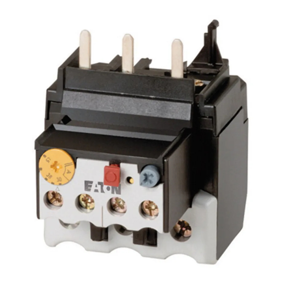
07/04 AWB2300-1545D/GB Motorschutzrelais ZB65 und ZB150 Geräteübersicht Abbildung 1: Motorschutzrelais ZB65 Abbildung 2: Motorschutzrelais ZB150 Abbildung 3: Motorschutzrelais ZB150-…KK For Sales and Support call KMparts.com (866) 595-9616... -
Seite 11: Gerätebeschreibung
Schütz ZB65 DILM40 DILM50 DILM65 ZB150 DILM80 DILM95 DILM115 DILM150 Zusätzlich sind die Relais ZB65 in Kombination mit einer Einzelaufstellung einzeln einsetzbar. Die Relais ZB150-…KK sind für Einzelaufstellung konzipiert. Einzelaufstellung Motorschutzrelais Einzelaufstellung ZB65 ZB65-XEZ ZB150-…KK – Bei einer Überlastauslösung schalten die Hilfsschalter 95-96 und 97-98 um und unterbrechen den Steuerstromkreis des zugehörigen Leistungsschützes. -
Seite 12: Strombereiche Der Motorschutzrelais
07/04 AWB2300-1545D/GB Motorschutzrelais ZB65 und ZB150 L1 L2 L3 (Q11/1) -S11 -Q11 -Q11 U V W Abbildung 4: Schaltbild eines Motorabganges mit Motorschutzrelais Sicherung Motorschutzrelais Motorschütz Motor Strombereiche der Motorschutzrelais Die Z-Relais werden mit Hilfe der Strom-Einstellscheibe auf den Motornennstrom eingestellt. - Seite 13 07/04 AWB2300-1545D/GB Gerätebeschreibung Tabelle 1: Strombereiche ZB65 Relais Strombereich I [A] ZB65-10 6 bis 10 ZB65-16 10 bis 16 ZB65-24 16 bis 24 ZB65-40 24 bis 40 ZB65-57 40 bis 57 ZB65-65 50 bis 65 Tabelle 2: Strombereiche ZB150 Relais...
-
Seite 14: Temperaturkompensation
Temperaturbereich –5 °C bis +55 °C konti- nuierlich durch Korrektur des Auslöseweges selbsttätig kompensiert. Phasenausfall Motorschutzrelais ZB65 und ZB150 sind phasenausfallemp- findlich. Die Auslenkung aller drei Bimetalle wirkt auf eine Auslösebrücke, die bei Erreichen des Grenzwertes einen Sprungschalter umschaltet. Gleichzeitig verschieben alle drei Bimetalle die Differenzialbrücke. -
Seite 15: Wiedereinschaltung
07/04 AWB2300-1545D/GB Gerätebeschreibung Soll mit einem ZB65 oder ZB150 Relais ein Wechselstrom- motor oder ein Gleichstrommotor überwacht werden, muss der Strom über alle drei Strombahnen geführt werden, um Frühauslösungen zu vermeiden. Abbildung 6: Verdrahtung der Motorschutzrelais für den Schutz von Wechselstrom- oder Gleichstrommotoren (Reihenschaltung der Bimetallauslöser) -
Seite 16: Testfunktion
07/04 AWB2300-1545D/GB Motorschutzrelais ZB65 und ZB150 Testfunktion Durch eine zusätzliche Testtaste kann die Funktionstüchtig- keit der Hilfsschalter kontrolliert werden. Hierbei hat die Testtaste eine Doppelfunktion: • Das Drücken der Testtaste öffnet den Öffner 95-96. Nach dem Loslassen fällt der Öffner wieder zurück. -
Seite 17: Projektierung
07/04 AWB2300-1545D/GB Projektierung Überlastüberwachung von Durch besondere konstruktive Maßnahmen erreicht man bei Motoren im EEx e-Bereich Motoren die Zündschutzart EEx e. Die Motoren werden auf Basis der höchst zulässigen Oberflächentemperaturen Temperaturklassen zugeordnet. Zusätzlich wird die Erwär- mungszeit t und das Verhältnis Anlaufstrom zu Nennstrom bestimmt und auf dem Motor angegeben. - Seite 18 07/04 AWB2300-1545D/GB Projektierung Beispiel: I = 6, t = 10 s 7 8 9 10 Abbildung 7: Auslösekennlinie des Motorschutzrelais Der Motor wird zuverlässig geschützt. For Sales and Support call KMparts.com (866) 595-9616...
-
Seite 19: Kurzschlussschutz Der Motorschutzrelais
Vorsicherung des Schützes für die entsprechende Zuord- nungsart mit berücksichtigt. Vorsicht! Zum Schutz von EEx e-Motoren ist nur die Zuordnungsart „2“ zulässig. Tabelle 3: ZB65 in Direktanbau oder Einzelaufstellung Schütz Sicherung gG/gL [A] Zuordnungsart „1“ Zuordnungsart „2“ ZB65-10 DILM40... -
Seite 20: Zulassungen
ZB150-125KK ZB150-150KK 1) nach IEC/EN 60947 Zulassungen Die Motorschutzrelais ZB65, ZB150 und ZB150-…KK sind nach der Vorschrift IEC EN 60947 Niederspannungsschalt- geräte gebaut und erfüllen die Forderungen nach der Richt- linie 94/9/EG (ATEX 100a) zum Schutz von EEx e-Motoren. II(2)GD... -
Seite 21: Installation
Installation Hinweise zur Installation Bei der mechanischen und elektrischen Installation ist die entsprechende Montageanweisung zu beachten. Die Monta- geanweisung liegt den ZB150 Relais bei und ist bei den ZB65 Relais auf der Innenseite der Kartonverpackung aufgedruckt. ZB65: AWA2300-2113 ZB150: AWA2300-2115 Warnung! Für den Explosionsschutz ist nur ein manuelles Rück-... - Seite 22 07/04 AWB2300-1545D/GB Installation L1 L2 L3 (Q11/1) -S11 -Q11 -Q11 U V W Abbildung 8: Schaltung verhindert automatischen Wiederanlauf F1 Sicherung F2 Motorschutzrelais Q11 Leistungsschütz M1 Motor Die Selbsthaltung des Leistungsschützes Q11 verhindert einen automatischen Wiederanlauf. For Sales and Support call KMparts.com (866) 595-9616...
-
Seite 23: Geräte Montieren
07/04 AWB2300-1545D/GB Geräte montieren Geräte montieren Die Motorschutzrelais ZB65 können sowohl direkt am Schütz montiert als auch in Kombination mit der Einzelaufstellung aufgebaut werden. Die ZB150 Relais sind für den Direktanbau an das Schütz gebaut, die ZB150-…KK werden einzeln aufgestellt. - Seite 24 07/04 AWB2300-1545D/GB Installation ZB65-XEZ DIL... ZB65 ZB65 Abbildung 9: Montage ZB65 Die Einzelaufstellungen ZB65-XEZ können auf einer Hutschiene oder direkt auf der Montageplatte montiert werden. DIL... ZB150-... Abbildung 10: Montage ZB150 For Sales and Support call KMparts.com (866) 595-9616...
- Seite 25 07/04 AWB2300-1545D/GB Geräte montieren Die ZB150-…KK werden direkt auf die Montageplatte montiert. Tabelle 8: Maße zur Montage ZB65-XEZ ZB150-…KK Bohrmaße (B x H) [mm] 50 x 75 100 x 74 Schraube [mm] 2 x (M5 x 12) 2 x (M6 x 20) Verdrahten Sie die Motorleitungen wie in Abb.
- Seite 26 07/04 AWB2300-1545D/GB Installation Hauptstrombahnen Hilfsstrom- bahnen ZB65 ZB150 95-96, 97-98 – 1 x (6 x16 x 0,8) – – 2 x (6 x 16 x 0,8) – [mm] 1 x (14 – 2) 1 x (6 – 2/0) 1 x (18 – 12) 2 x (14 –...
-
Seite 27: Geräte Betreiben
Motornennstrom mit Hilfe einer Stromeinstellscheibe am Relais eingestellt werden (a Tabelle 1 und Tabelle 2 auf Seite 9). Rücksetzung Die Motorschutzrelais ZB65 und ZB150 bieten mit Hilfe des Wahlknopfes Reset die Möglichkeit, zwischen einem auto- matischem Wiederanlauf „A“ und einer Handrücksetzung „H“ zu wählen. -
Seite 28: Test
07/04 AWB2300-1545D/GB Geräte betreiben Test Die Motorschutzrelais ZB65 und ZB150 sind mit einer Taste Test versehen, in der eine Doppelfunktion integriert ist. TEST NO 97 NC 95 NO 98 NC 96 Abbildung 13: Schaltmöglichkeiten der Taste Test Ein Ziehen der Taste hat das Öffnen des Hilfskontaktes 95-96 zur Folge und kann zum Abschalten des Schützes... - Seite 54 07/04 AWB2300-1545D/GB Anhang/Appendix Tabelle/Table 10: Werte der einzelnen Typen/Values of the various types ZB65-10 6 – 10 A ZB65-16 10 – 16 A ZB65-24 16 – 24 A ZB65-40 24 – 40 A ZB65-57 40 – 57 A ZB65-65 50 – 65 A...
-
Seite 55: Motorschutzrelais/Overload Relay Zb150
07/04 AWB2300-1545D/GB Typenschilder/Rating plates Motorschutzrelais/Overload relay ZB150 imp 8000 V "1" A gL 1000 V h "2" Normal Test AC–15 380/415 500Vh 220/240 95–96: 0,8 A 97–98: 0,5 A imp 6000 V th 6 A II(2)GD 0102 PTB 04 ATEX 3022 IEC/EN 60947 IND. - Seite 56 07/04 AWB2300-1545D/GB Anhang/Appendix Die Zuordnungen der Werte zu den jeweiligen Typen sind der nachfolgenden Tabelle 11 zu entnehmen. For information on the assignment of values to the relevant types, please refer to Tabelle 11. Tabelle/Table 11: Werte der einzelnen Typen/Values of the various types ZB150-35 25 –...
-
Seite 57: Auslösekennlinien/Tripping Characteristics
07/04 AWB2300-1545D/GB Auslösekennlinien/ Tripping characteristics Auslösekennlinien/ Tripping characteristics For Sales and Support call KMparts.com (866) 595-9616... -
Seite 58: Zb65
Toleranzbereich/Tolerance range g 20 % Einstellung/ Auslösezeit/Tripping time t [s] Setting 3-phase a 2-phase c 3-phase b 2-phase d 3 x I 16.5 7.2 x I 7 8 9 10 Abbildung/Figure 16: ZB65-10 For Sales and Support call KMparts.com (866) 595-9616... -
Seite 59: Zb65
Toleranzbereich/Tolerance range g 20 % Einstellung/ Auslösezeit/Tripping time t [s] Setting 3-phase a 2-phase c 3-phase b 2-phase d 3 x I 29.7 7.2 x I 7 8 9 10 Abbildung/Figure 17: ZB65-16 For Sales and Support call KMparts.com (866) 595-9616... -
Seite 60: Zb65
Toleranzbereich/Tolerance range g 20 % Einstellung/ Auslösezeit/Tripping time t [s] Setting 3-phase a 2-phase c 3-phase b 2-phase d 3 x I 24.5 7.2 x I 7 8 9 10 Abbildung/Figure 18: ZB65-24 For Sales and Support call KMparts.com (866) 595-9616... -
Seite 61: Zb65
20 % Einstellung/ Auslösezeit/Tripping time t [s] Setting 3-phase a 2-phase c 3-phase b 2-phase d 3 x I 23.5 18.2 13.2 7.2 x I 7 8 9 10 Abbildung/Figure 19: ZB65-40 For Sales and Support call KMparts.com (866) 595-9616... -
Seite 62: Zb65
20 % Einstellung/ Auslösezeit/Tripping time t [s] Setting 3-phase a 2-phase c 3-phase b 2-phase d 3 x I 28.8 16.6 7.2 x I Z1-57 7 8 9 10 Abbildung/Figure 20: ZB65-57 For Sales and Support call KMparts.com (866) 595-9616... -
Seite 63: Zb65
20 % Einstellung/ Auslösezeit/Tripping time t [s] Setting 3-phase a 2-phase c 3-phase b 2-phase d 3 x I 26.4 18.5 23.9 7.2 x I 7 8 9 10 Abbildung/Figure 21: ZB65-65 For Sales and Support call KMparts.com (866) 595-9616... -
Seite 64: Zb150-35, Zb150-35Kk
07/04 AWB2300-1545D/GB Anhang/Appendix ZB150-35, ZB150-35KK Bereich/Range 25 – 35 A (NM – HM) Umgebungstemperatur/Ambient temperature 20 °C Auslöseklasse/Tripping class 10 A Toleranzbereich/Tolerance range g 20 % Einstellung/ Auslösezeit/Tripping time t [s] Setting 3-phase a 2-phase c 3-phase b 2-phase d 3 x I 7.2 x I 7 8 9 10... - Seite 65 07/04 AWB2300-1545D/GB Auslösekennlinien/ Tripping characteristics ZB150-50 Bereich/Range 35 – 50 A (NM – HM) Umgebungstemperatur/Ambient temperature 20 °C Auslöseklasse/Tripping class 10 A Toleranzbereich/Tolerance range g 20 % Einstellung/ Auslösezeit/Tripping time t [s] Setting 3-phase a 2-phase c 3-phase b 2-phase d 3 x I 15.8 13.8...
-
Seite 66: Zb150-50Kk
07/04 AWB2300-1545D/GB Anhang/Appendix ZB150-50KK Bereich/Range 36 – 50 A (NM – HM) Umgebungstemperatur/Ambient temperature 20 °C Auslöseklasse/Tripping class 10 A Toleranzbereich/Tolerance range g 20 % Einstellung/ Auslösezeit/Tripping time t [s] Setting 3-phase a 2-phase c 3-phase b 2-phase d 3 x I 12.8 7.2 x I 7 8 9 10... -
Seite 67: Zb150-70, Zb150-70Kk
07/04 AWB2300-1545D/GB Auslösekennlinien/ Tripping characteristics ZB150-70, ZB150-70KK Bereich/Range 50 – 70 A (NM – HM) Umgebungstemperatur/Ambient temperature 20 °C Auslöseklasse/Tripping class 10 A Toleranzbereich/Tolerance range g 20 % Einstellung/ Auslösezeit/Tripping time t [s] Setting 3-phase a 2-phase c 3-phase b 2-phase d 3 x I 15.3... -
Seite 68: Zb150-100
07/04 AWB2300-1545D/GB Anhang/Appendix ZB150-100 Bereich/Range 70 – 100 A (NM – HM) Umgebungstemperatur/Ambient temperature 20 °C Auslöseklasse/Tripping class 10 A Toleranzbereich/Tolerance range g 20 % Einstellung/ AuslösezeitTripping time t [s] Setting 3-phase a 2-phase c 3-phase b 2-phase d 3 x I 7.2 x I 7 8 9 10 Abbildung/Figure 26: ZB150-100... -
Seite 69: Zb150-100Kk
07/04 AWB2300-1545D/GB Auslösekennlinien/ Tripping characteristics ZB150-100KK Bereich/Range 70 – 1000 A (NM – HM) Umgebungstemperatur/Ambient temperature 20 °C Auslöseklasse/Tripping class 10 A Toleranzbereich/Tolerance range g 20 % Einstellung/ Auslösezeit/Tripping time t [s] Setting 3-phase a 2-phase c 3-phase b 2-phase d 3 x I 7.2 x I 7 8 9 10... -
Seite 70: Zb150-125, Zb150-125Kk
07/04 AWB2300-1545D/GB Anhang/Appendix ZB150-125, ZB150-125KK Bereich/Range 95 – 125 A (NM – HM) Umgebungstemperatur/Ambient temperature 20 °C Auslöseklasse/Tripping class 10 A Toleranzbereich/Tolerance range g 20 % Einstellung/ Auslösezeit/Tripping time t [s] Setting 3-phase a 2-phase c 3-phase b 2-phase d 3 x I 24.5 7.2 x I... -
Seite 71: Zb150-150
07/04 AWB2300-1545D/GB Auslösekennlinien/ Tripping characteristics ZB150-150 Bereich/Range 120 – 150 A (NM – HM) Umgebungstemperatur/Ambient temperature 20 °C Auslöseklasse/Tripping class 10 A Toleranzbereich/Tolerance range g 20 % Einstellung/ Auslösezeit/Tripping time t [s] Setting 3-phase a 2-phase c 3-phase b 2-phase d 3 x I 7.2 x I 7 8 9 10... -
Seite 72: Zb150-150Kk
07/04 AWB2300-1545D/GB Anhang/Appendix ZB150-150KK Bereich/Range 120 – 150 A (NM – HM) Umgebungstemperatur/Ambient temperature 20 °C Auslöseklasse/Tripping class 10 A Toleranzbereich/Tolerance range g 20 % Einstellung/ Auslösezeit/Tripping time t [s] Setting 3-phase a 2-phase c 3-phase b 2-phase d 3 x I 7.2 x I 7 8 9 10 Abbildung/Figure 30: ZB150-150KK... -
Seite 73: Konformitätserklärung/Declaration Of Conformity
07/04 AWB2300-1545D/GB Konformitätserklärung/Decla- ration of Conformity Konformitätserklärung/ ZB65-… Declaration of Conformity For Sales and Support call KMparts.com (866) 595-9616...