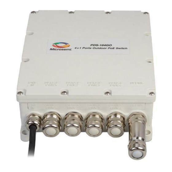
Microsemi PDS-104GO Hardwarespezifikationen Und Installationsanleitung
Outdoor poe switch 4 poe ports + 1 sfp uplink port

Verwandte Anleitungen für Microsemi PDS-104GO


Inhaltszusammenfassung für Microsemi PDS-104GO
-
Seite 24: Technischer Kundendienst
Eigentumsrechten muss von einem leitenden Microsemi Angestellten schriftlich genehmigt und unterzeichnet werden. Microsemi behält sich das Recht vor, die Konfiguration, Funktionalität und Leistung ihrer Produkte jederzeit ohne vorherige Ankündigung ändern zu können. Dieses Produkt ist eingeschränkten Tests unterzogen worden und sollte nicht zusammen mit lebenserhaltenden oder anderen unternehmenskritischen Geräten und Anwendungen eingesetzt werden. - Seite 25 3. Hardware-Beschreibung ..........27 4. Mechanische Ansicht ..........28 5. Installation ..............29 5.1 Installationsmöglichkeiten für den PDS-104GO ..29 6. Anschluss der Netzwerkkabel ........33 6.1 Anschluss des Gigabit Ethernet Kabels ....33 6.2 Anschluss des Glasfaserkabels ......38 6.3 Erste Schritte zur Switch-Konfiguration ....
-
Seite 26: Vorwort
Dokuments. 1.1 Zugehörige Dokumente Weitere Informationen finden Sie in folgenden Dokumenten: Microsemi PDS-104 Software (NMS) Anleitung 1.2 Zielgruppe Diese Anleitung richtet sich an den Personenkreis, der für die Installation und Wartung des Routers verantwortlich ist. Bei diesen Personen sollte es sich um erfahrene Elektroniker oder Elektromechanik-Techniker handeln, die mit der Elektronik und den Verdrahtungstechniken vertraut sind. -
Seite 27: Einführung
Außenbereich. Er kann vier elektrisch betriebene Geräte mit Strom versorgen, ihnen eine Datenverbindung bieten und sie mit Hilfe seiner Datenübermittlungsschnittstelle mit dem Netzwerk verbinden. Der PDS-104GO/AC/M kann über das Internet oder SNMP fernverwaltet werden, einschließlich der Überwachung und Steuerung des Geräts und seiner aadvs-Schnittstellen. Der PDS-104GO/AC/M unterstützt 10/100/1000Mbps... -
Seite 28: Mechanische Ansicht
Eine Glasfaserkabelverschraubung + Kabelverschraubungs-Extender Fünf Kabelverschraubungskappen Mechanische Montagesatz-Option für die Mastmontage (optional, wird getrennt verkauft) 4. Mechanische Ansicht Copyright © 2016 Microsemi Page 28 of 48 CPG – PoE BU Rev. A00 One Enterprise Aliso Viejo, CA 92656 USA... -
Seite 29: Installation
5.1 Installationsmöglichkeiten für den PDS-104GO Die folgenden zwei Abschnitte beschreiben die Installationsmöglichkeiten. 5.1.1 Wandmontage Die PDS-104GO Einheit kann mit Hilfe der Montagelöcher an einer Wand / einer Arbeitsfläche (alle Arten von flachen Oberflächen: Holz, Mauerstein, Beton usw.) befestigt werden. Befestigen Sie den PDS-104GO mit Hilfe der vier Schrauben, siehe Abbildung 5-1. - Seite 30 Mit Hilfe des optionalen Montagesatzes (wird getrennt verkauft). Mastmontage mit Hilfe des optionalen Montagesatzes (wird getrennt vekauft) Schritt 1 Copyright © 2016 Microsemi Page 30 of 48 CPG – PoE BU Rev. A00 One Enterprise Aliso Viejo, CA 92656 USA...
- Seite 31 Schritt 2 Vorsicht Die Montageklammer muss geerdet werden! Schritt 3 Für Mastdurchmesser von 25,4 mm < ø < 76,2 mm Copyright © 2016 Microsemi Page 31 of 48 CPG – PoE BU Rev. A00 One Enterprise Aliso Viejo, CA 92656 USA...
- Seite 32 Schritt 4 Für Mastdurchmesser von 76,2 mm < ø < 203,2 mm Copyright © 2016 Microsemi Page 32 of 48 CPG – PoE BU Rev. A00 One Enterprise Aliso Viejo, CA 92656 USA...
-
Seite 33: Anschluss Der Netzwerkkabel
6. Anschluss der Netzwerkkabel Dieser Abschnitt beschreibt, wie die folgenden PDS-104GO Schnittstellen angeschlossen werden: Anschluss des Gigabit Ethernet Kabels Hinweis Der PDS-104 wird nicht mit Ethernet-Kabel und RJ45- Steckergeliefert. Schritt 1 Entfernen Sie die Metallverschraubung von der PDS- 104GO Einheit, indem Sie sie gegen den Uhrzeigersinn drehen. - Seite 34 Schritt 2 Schieben Sie Metallverschraubung, Gummidichtung und Druckfinger in dieser Reihenfolge auf das Ethernetkabel. Vergrößert Ethernetkabel Druckfinger Metallverschraubung PDS-104GO Einheit Gummidichtung Hinweis Achten Sie auf die richtige Reihenfolge und Richtung. Siehe Schritt 3 Copyright © 2016 Microsemi Page 34 of 48 CPG –...
- Seite 35 Schritt 3 Schieben Sie die Gummidichtung in die Druckfinger Schritt 4 Schieben Sie den RJ45-Stecker in die RJ45- Buchse, bis die Druckknöpfe richtig sitzen. Copyright © 2016 Microsemi Page 35 of 48 CPG – PoE BU Rev. A00 One Enterprise Aliso Viejo, CA 92656 USA...
- Seite 36 Buchse, bis die Druckknöpfe richtig sitzen. Schritt 6 Drehen Sie die Metallverschraubung im Uhrzeigersinn mit einem Drehmoment von 7,6 Nm in den PDS-104GO. Hinweis Beginnen Sie zuerst mit der Montage des Anschlusses Nr. 1 (Daten & STROM 1) und heben den Datenübermittlungsanschluss bis zum Schluss auf.
- Seite 37 STEP-1 STEP-2 STEP-3 STEP-4 STEP-5 STEP-6 TORQUE 7.5Nm Copyright © 2016 Microsemi Page 37 of 48 CPG – PoE BU Rev. A00 One Enterprise Aliso Viejo, CA 92656 USA...
-
Seite 38: Anschluss Des Glasfaserkabels
Datenübermittlungsanschluss bis zum Schluss auf. Hinweis Benutzen Sie einen Splitter für nicht AF/AT konforme Einheiten – vergewissern Sie sich, dass der Splitter in der Copyright © 2016 Microsemi Page 38 of 48 CPG – PoE BU Rev. A00... -
Seite 39: Erste Schritte Zur Switch-Konfiguration
Hinweis Diese Einheit ist für den Einsatz im Freien geeignet. 6.3 Erste Schritte zur Switch-Konfiguration Standard IP Adresse: 192.168.0.50 Copyright © 2016 Microsemi Page 39 of 48 CPG – PoE BU Rev. A00 One Enterprise Aliso Viejo, CA 92656 USA... -
Seite 40: Anhang A. Sicherheits- Und Warnhinweise
Eine Nichtübereinstimmung der Spannung kann die Geräte beschädigen und eine Feuergefahr darstellen. Wenn die auf dem Aufkleber angezeigte Spannung von der Spannung abweicht, die an der Steckdose anliegt, schließen Sie den PDS-104GO nicht an diese Steckdose an! Alle Verdrahtungen und Anschlüsse müssen in Übereinstimmung mit NFPA 70 (NEC) ausgeführt werden. - Seite 41 Vergewissern Sie sich, dass sich die Netzspannung innerhalb des zulässigen Bereichs befindet. Copyright © 2016 Microsemi Page 41 of 48 CPG – PoE BU Rev. A00 One Enterprise Aliso Viejo, CA 92656 USA...
-
Seite 42: Anhang B. Fehlerbehebung
Sie ihn mit einem Splitter, von dem Sie verbindung wissen, dass er funktioniert. 3. Vergewissern Sie sich, dass Sie für diese Verbindung ein standardmäßiges gerade Copyright © 2016 Microsemi Page 42 of 48 CPG – PoE BU Rev. A00 One Enterprise Aliso Viejo, CA 92656 USA... -
Seite 43: Umweltbezogene Spezifikationen
100 – 240 VAC (50 – 60 Hz) Eingangsspannung Eingangsstrom 2.5 Ampere (max) (100 – 240 VAC) Verfügbarer Ausgangsstrom 150 Watt (max.) Nominal Ausgangsspannung 54 VDC Copyright © 2016 Microsemi Page 43 of 48 CPG – PoE BU Rev. A00 One Enterprise Aliso Viejo, CA 92656 USA... - Seite 44 30W Anschlüsse (Anschlüsse 3 & Paare 1-2 & 3-6 3 Pins AC Stromeingang – AC Stromeingang Netzspannung, Neutralleiter und Erdung Copyright © 2016 Microsemi Page 44 of 48 CPG – PoE BU Rev. A00 One Enterprise Aliso Viejo, CA 92656 USA...
-
Seite 45: Anhang D. Standards
104GO/AC/M: UL60950-1 UL60950-22 CB & GS Erfüllung Blitzschutz des PDS-104GO/AC/M: Das Gerät ist darauf ausgelegt, die Anforderungen des GR- 1089-CORE Blitzschutzes zu erfüllen. Andere Standards und Genehmigungen: IEEE 802.3at & IEEE 802.3af (PoE) Standards ... -
Seite 46: Anhang E. Wiederverwertung Und Entsorgung
Sie das alte Produkt (einschließlich aller seiner Komponenten) an den Händler zurück. Er sollte das Gerät, wie von der nationalen WEEE Gesetzgebung gefordert, zurücknehmen. Copyright © 2016 Microsemi Page 46 of 48 CPG – PoE BU Rev. A00 One Enterprise Aliso Viejo, CA 92656 USA... - Seite 47 Bestellinformationen: Produktname: Microsemi PoE Switch für den Außenbereich Teilenummer: PDS-104GO/AC/M Beschreibung: 4 PoE Anschlüsse + 1 SFP Datenübermittlungsanschluss Montagesatz (wird getrennt verkauft) Produktname: Montagesatz für den Außenbereich Teilenummer: PD-OUT/MBK/S Dokumenten-Teilenummer: 06-6620-170 Copyright © 2016 Microsemi Page 47 of 48 CPG – PoE BU Rev.