Werbung
Quicklinks
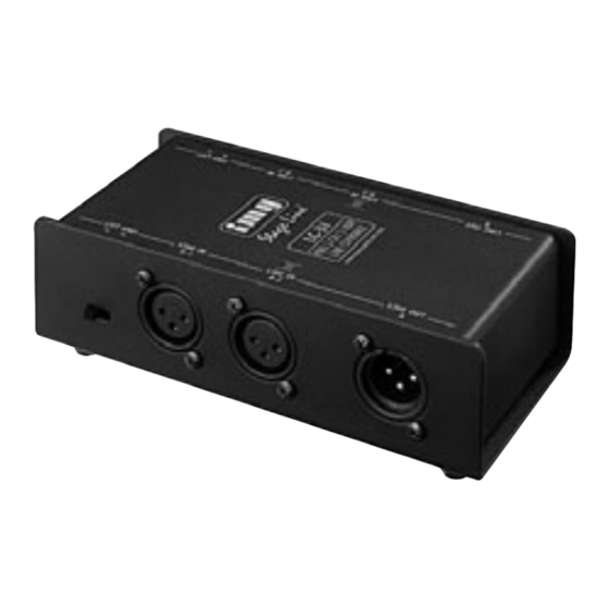
LC-31
Best.-Nr. 25.1670
D
A
CH
2-Kanal-Line-Signal-
Mischadapter
1 Einsatzmöglichkeiten
Der LC-31 ist dafür konzipiert, zwei Line-Signale
zu einem zusammenzumischen. Er hat zwei
unabhängige Signalwege (A und B), sodass z. B.
die Stereo-Ausgänge zweier Mischpulte an den
Stereo-Eingang eines Verstärkers angeschlos-
sen werden können.
Zur galvanischen Trennung der beiden Sig-
nalquellen wird jeweils ein Eingangssignal über
einen Übertrager geführt. Zusätzlich kann die
Signalmasse dieses entkoppelten Eingangs mit-
hilfe eines Schalters von der Masse des Aus-
gangs und der Masse des anderen Eingangs
getrennt werden. So lässt sich eine Masse-
schleife, die ein störendes Brummen verursa-
chen kann, auftrennen. Sie entsteht z. B. wenn
beide Signalquellen sowohl über die Signal-
masse als auch über den Schutzleiter der
Stromversorgung oder über eine leitende Ver-
bindung der Gehäuse im Rack Kontakt haben.
2 Wichtige Hinweise für den Gebrauch
Das Gerät entspricht allen erforderlichen Richt-
linien der EU und ist deshalb mit
zeichnet.
Verwenden Sie das Gerät nur im Innenbereich.
2-Channel Line Signal Mixing
GB
Adapter
1 Applications
The LC-31 has been designed to mix together
two line signals to one signal. It has two inde-
pendent signal ways (A and B) so that e. g. the
stereo outputs of two mixers may be connected
to the stereo input of an amplifier.
For galvanic isolation of the two signal
sources one input signal each is led via a trans-
former. In addition, the signal ground of this
decoupled input can be separated by means of
a switch from the ground of the output and the
ground of the other input. Thus, a ground loop
which may cause an interfering hum noise can
be interrupted. It occurs e. g. when the two sig-
nal sources have contact in the rack both via the
signal ground and via the earthed conductor of
the power supply or a conductive connection of
the housings.
2 Important Notes
The unit corresponds to all required directives of
the EU and is therefore marked with
The unit is suitable for indoor use only. Protect
it against dripping water and splash water,
high air humidity, and heat (admissible
ambient temperature range 0 – 40 °C).
Prinzipschaltbild (1 Kanal) • Basic circuit diagram (1 channel)
2
3
1
LINE IN 1
2
3
1
LINE IN 2
®
Copyright
Schützen Sie es vor Tropf- und Spritzwasser,
hoher Luftfeuchtigkeit und Hitze (zulässiger
Einsatztemperaturbereich 0 – 40 °C).
Verwenden Sie für die Reinigung nur ein
trockenes, weiches Tuch, niemals Chemika-
lien oder Wasser.
Wird das Gerät zweckentfremdet, nicht richtig
angeschlossen, falsch bedient oder nicht
fachgerecht repariert, kann keine Haftung für
daraus resultierende Sach- oder Personen-
schäden und keine Garantie für das Gerät
übernommen werden.
Soll das Gerät endgültig aus dem Be-
trieb genommen werden, übergeben
Sie es zur umweltgerechten Entsor-
gung einem örtlichen Recyclingbetrieb.
3 Anschlüsse herstellen
1) Zur Vermeidung von Schaltgeräuschen die an
die Ausgänge anzuschließenden Geräte
zunächst ausschalten oder deren Eingänge
stummschalten oder herunterregeln.
2) Die Ausgänge der ersten Audioquelle an die
Eingangsbuchsen LINE IN 1 (2) anschließen.
3) Die Ausgänge der zweiten Audioquelle an die
gekenn-
Eingangsbuchsen LINE IN 2 (3) anschließen.
Dieser Eingang ist durch einen Übertrager
von dem ersten Eingang und dem Ausgang
For cleaning only use a dry, soft cloth, by no
means chemicals or water.
No guarantee claims for the unit and no liabil-
ity for any resulting personal damage or mate-
rial damage will be accepted if the unit is used
for other purposes than originally intended, if it
is not correctly connected, operated, or not
repaired in an expert way.
If the unit is to be put out of operation
definitively, take it to a local recycling
plant for a disposal which is not harm-
ful to the environment.
3 Connections
1) To prevent switching noise, for the time being
switch off the units to be connected to the out-
puts, or mute their inputs or reduce them.
2) Connect the outputs of the first audio source
to the input jacks LINE IN 1 (2).
3) Connect the outputs of the second audio
source to the input jacks LINE IN 2 (3). This
input is galvanically isolated from the first
.
input and the output by a transformer. In addi-
tion, the ground connection of this input can
be separated with the groundlift switch from
the ground of the connections LINE IN 1 (2)
and LINE OUT (4).
2
3
1
LINE OUT
GND
LIFT
©
by MONACOR INTERNATIONAL GmbH & Co. KG, Bremen, Germany. All rights reserved.
galvanisch getrennt. Die Masseverbindung
dieses Anschlusses kann zudem mit dem
Groundlift-Schalter von der Masse der
Anschlüsse LINE IN 1 (2) und LINE OUT (4)
getrennt werden.
4) Den jeweiligen Ausgang LINE OUT (4) mit
dem Eingang des nachfolgenden Audiogerä-
tes (z. B. Verstärker, Mischpult) verbinden.
5) Wenn nötig, den jeweiligen Groundlift-Schal-
ter (1) von der Position GND auf die Position
LIFT (Massen getrennt) umschalten.
4 Technische Daten
Entkopplungswiderstände: . . . . . 1 kΩ
Optimale Quellimpedanz: . . . . . . . 50 – 600 Ω
Optimale Lastimpedanz: . . . . . . . ≥ 5 kΩ
Eigenschaften des Übertragers
Frequenzbereich: . . . . . . . . . . 20 – 20 000 Hz
Impedanz: . . . . . . . . . . . . . . . 600 Ω bei 1 kHz
Max. Eingangsspannung
bei 1 % Klirrfaktor, 40 Hz: . . . . 5 V
Abmessungen: . . . . . . . . . . . . . . 160 × 55 × 85 mm
Gewicht: . . . . . . . . . . . . . . . . . . . 780 g
Änderungen vorbehalten.
4) Connect the corresponding output LINE OUT
(4) to the input of the following audio unit (e. g.
amplifier, mixer).
5) If required, switch the corresponding ground-
lift switch (1) from position GND to position
LIFT (grounds separated).
4 Specifications
Decoupling resistors: . . . . . . . . . 1 kΩ
Optimum source
impedance: . . . . . . . . . . . . . . . . . 50 – 600 Ω
Optimum load impedance: . . . . . ≥ 5 kΩ
Characteristics of the transformer
frequency range: . . . . . . . . . . 20 – 20 000 Hz
impedance: . . . . . . . . . . . . . . 600 Ω at 1 kHz
max. input voltage
at 1% THD, 40 Hz: . . . . . . . . . 5 V
Dimensions: . . . . . . . . . . . . . . . . 160 × 55 × 85 mm
Weight: . . . . . . . . . . . . . . . . . . . . 780 g
Subject to technical modification.
1
2
1
2
LIFT GND
LINE IN
LINE IN
A-1
A-2
3
4
3
4
LINE OUT
A
A-0680.99.01.12.2006
Werbung

Verwandte Anleitungen für IMG STAGELINE LC-31


Inhaltszusammenfassung für IMG STAGELINE LC-31
- Seite 1 1 Applications ity for any resulting personal damage or mate- lift switch (1) from position GND to position The LC-31 has been designed to mix together rial damage will be accepted if the unit is used LIFT (grounds separated). two line signals to one signal. It has two inde- for other purposes than originally intended, if it pendent signal ways (A and B) so that e.
- Seite 2 1 Possibilités d’utilisation avec l’interrupteur Groundlift. Pour le nettoyage, utilisez uniquement un chif- Le LC-31 est conçu pour mixer ensemble deux fon sec et doux, en aucun cas de produits chi- 4) Reliez la sortie correspondante LINE OUT (4) signaux ligne en un seul. Il a deux voies indé- miques ou d’eau.
- Seite 3 Para la limpieza use sólo un paño seco y suave, LINE IN 1 (2) y LINE OUT (4). El LC-31 ha sido diseñado para mezclar conjun- no utilice nunca productos químicos o agua. tamente dos señales de línea en una sola señal.