
Verwandte Anleitungen für Balluff BIP LD2-T017-01-EP Serie


Inhaltszusammenfassung für Balluff BIP LD2-T017-01-EP Serie
- Seite 1 BIP LD2-T017-01-EP _ _ -S4 BIP LD2-T017-01-EP _ _ deutsch Betriebsanleitung english User’s guide français Notice d’utilisation italiano Manuale d’uso español Manual de instrucciones 中文 使用说明书 日本語 取扱説明書...
- Seite 2 www.balluff.com...
- Seite 3 BIP LD2-T017-01-EP _ _ -S4 BIP LD2-T017-01-EP _ _ Betriebsanleitung deutsch...
- Seite 4 www.balluff.com...
-
Seite 5: Inhaltsverzeichnis
Schaltsignalkonfiguration (Switching Signal Channels, SSC) Direktes Teach-In der Schaltkanäle 6.10 Condition Monitor 6.11 Hubzähler 6.12 Sensorspezifische Parameter (Hubzähler) 6.13 Systemkommandos für den Hubzähler 6.14 Beispiele (Hubzähler) 6.15 Diagnosedaten 6.16 Geräte-Fehlermeldungen Technische Daten Genauigkeit Umgebungsbedingungen Spannungsversorgung IO-Link-Schnittstelle Mechanische Daten Zubehör www.balluff.com deutsch... -
Seite 6: Benutzerhinweise
BIP LD2-T017-01-EP _ _ / EP _ _ -S4 Induktives Positionsmesssystem Benutzerhinweise Gültigkeit Zulassungen und Kennzeichnungen Diese Anleitung beschreibt Aufbau, Funktion und Einstell- möglichkeiten des induktiven Positionsmesssystems BIP mit IO-Link-Schnittstelle. Sie gilt für die Typen BIP LD2-T017-01-EP _ _ -S4 und BIP LD2-T017-01-EP _ _. Die Anleitung richtet sich an qualifizierte Fachkräfte. Lesen Sie diese Anleitung, bevor Sie das BIP installieren und Mit dem CE-Zeichen bestätigen wir, betreiben. -
Seite 7: Sicherheit
Defekt des BIP keine Gefahren für Perso- Entsorgung nen und Sachen entstehen können. ► Befolgen Sie die nationalen Vorschriften zur Entsor- Bei Defekten und nichtbehebbaren Störungen des BIP ist gung. dieses außer Betrieb zu nehmen und gegen unbefugte Benutzung zu sichern. www.balluff.com deutsch... -
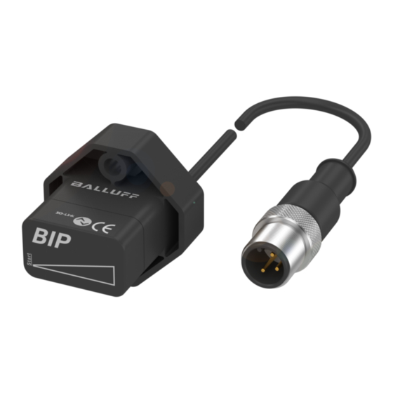
Seite 8: Aufbau Und Funktion
BIP LD2-T017-01-EP _ _ / EP _ _ -S4 Induktives Positionsmesssystem Aufbau und Funktion Aufbau Ø ≤ 3.5 15.1 Start Bild 3-1: Aufbau Funktion Das induktive Positionsmesssystem BIP erfasst die Posi- tion des metallischen Positionsgebers und gibt diese als IO-Link-Ausgangssignal aus. deutsch... -
Seite 9: Einbau Und Anschluss
Die Messrichtung verläuft entlang des keilförmigen Sym- 25.5 bols (Kennzeichnung auf der aktiven Fläche). Montage ► BIP mit 2 Befestigungsschrauben DIN EN ISO 4762 M4 x 10 befestigen (max. Anzugsdrehmoment: 0,5 Nm). Bild 4-2: Einbaumaße Positionsgeber BAM TG-XE-020 17.5 Bild 4-3: Abstand zur Messfläche www.balluff.com deutsch... -
Seite 10: Elektrischer Anschluss
BIP LD2-T017-01-EP _ _ / EP _ _ -S4 Induktives Positionsmesssystem Einbau und Anschluss (Fortsetzung) Elektrischer Anschluss Bild 4-4: Pinbelegung Steckverbinder S4 (Draufsicht auf Stecker am BIP) Stecker/ Adernfarbe Signal Braun L+ (18 30 V) … – nicht belegt Blau L– (GND) Schwarz C/Q (Kommunikationsleitung) Nicht belegte Adern können steuerungsseitig mit GND verbunden werden, aber nicht mit dem Schirm. -
Seite 11: Inbetriebnahme
Reparatur durch den Hersteller die korrekten Werte im Nullpunkt und Endpunkt prüfen. Hinweise zum Betrieb – Funktion des BIP und aller damit verbundenen Kompo- nenten regelmäßig prüfen. – Bei Funktionsstörungen das BIP außer Betrieb neh- men. – Anlage gegen unbefugte Benutzung sichern. www.balluff.com deutsch... -
Seite 12: Io-Link-Schnittstelle
BIP LD2-T017-01-EP _ _ / EP _ _ -S4 Induktives Positionsmesssystem IO-Link-Schnittstelle Grundwissen IO-Link Parameter-Management In der Protokollversion 1.1 ist ein Parametermanager Allgemein definiert, der das Speichern von Device-Parametern auf dem IO-Link-Master ermöglicht. Bei Austausch eines IO-Link integriert konventionelle und intelligente Sensoren IO-Link-Devices können die Parameterdaten des zuletzt und Aktoren in Automatisierungssysteme und ist als installierten IO-Link-Devices übernommen werden. -
Seite 13: Kommunikationsparameter
Master zum Device Herstellerkennung Vendor ID 0x378 Gerätekennung Device ID 0x020309 Tab. 6-1: Device-Spezifikation Übertragungszeiten Prozessdatenzyklus bei 1.0 Master Anzahl PD × master cycle time = 2 × 3 ms = 6 ms Prozessdatenzyklus bei 1.1 Master master cycle time = 3 ms Tab. 6-2: Device-Übertragungszeiten www.balluff.com deutsch... -
Seite 14: Prozessdaten
BIP LD2-T017-01-EP _ _ / EP _ _ -S4 Induktives Positionsmesssystem IO-Link-Schnittstelle (Fortsetzung) Prozessdaten Das BIP gibt über die IO-Link-Schnittstelle 2-Byte-Prozess- daten aus. Die Prozessdatenstruktur ist im Smart-Sensor- Profil Ed.2 beschrieben. Bit offset SDCI IntegerT(16) IntegerT(8) 8 bit Transmission Measurement value Scale Vendor specific direction Byte 3 Byte 2... - Seite 15 Identifikationsdaten Index Parameter Datenformat (Länge) Zugriff Inhalt hex (dez) 0x0010 (16) Vendor Name StringT (7 Byte) Read only „BALLUFF“ 0x0011 (17) Vendor Text StringT (21 Byte) Read only „innovating automation“ 0x0012 (18) Product Name StringT (25 Byte) Read only „BIP LD2-T017-01-EP00,5-S4“ 0x0013 (19) Product ID StringT (7 Byte)
-
Seite 16: Systemparameter
BIP LD2-T017-01-EP _ _ / EP _ _ -S4 Induktives Positionsmesssystem IO-Link-Schnittstelle (Fortsetzung) Systemparameter Index Parameter Subindex Parameter Datenformat Zugriff Werte- Bemerkungen hex (dez) hex (dez) bereich 0x000D ProfileCha- 0x01 (1) DeviceProfileID UINT16 Read only 0x0001 Smart-Sensor-Profil (13) racteristic 0x02 (2) 0x000A Measuring Sensor Profile (16 Bit) Smart-Sensor-Profil ist inherent. -
Seite 17: Sensorspezifische Parameter
Read only 0x02 (2) MDC High Limit int16 (2 Bytes) Read only (17000) 0x03 (3) MDC Unit Code uint16 (2 Bytes) Read only 1010 Unit Code für μm 0x04 (4) MDC Scale int8 (1 Byte) Read only –6 Tab. 6-8: Sensorspezifische Parameter www.balluff.com deutsch... -
Seite 18: Systembefehle
BIP LD2-T017-01-EP _ _ / EP _ _ -S4 Induktives Positionsmesssystem IO-Link-Schnittstelle (Fortsetzung) Systembefehle Beim BIP sind verschiedene Befehle implementiert, die über den Parameter System Command auf Index 2, Subindex 0 erreicht werden können. Wird ein Systembefehl an das BIP übermittelt, löst der Befehl die gewünschte Aktion aus, sofern dies im aktuellen Applikationszustand zulässig ist. -
Seite 19: Schaltsignalkonfiguration (Switching Signal Channels, Ssc)
INT16 –32000…+32000 0x4003 Switching Signal 0x01 logic UINT8 0x00 : normal mode configuration SSC4 0x01: inverted mode 0x02 mode UINT8 0x01: Single point 0x02: Window mode 0x03 Two Point mode 0x03 hysteresis INT16 50…16900 μm Tab. 6-10: Profilspezifische Parameter www.balluff.com deutsch... - Seite 20 BIP LD2-T017-01-EP _ _ / EP _ _ -S4 Induktives Positionsmesssystem IO-Link-Schnittstelle (Fortsetzung) Einzelpunktmodus Hysterese Positionswert Bild 6-2: Beispiel für die Präsenzerkennung im Einzelpunkt-Modus Index Subindex Zugriff Daten 1. Schaltkanal auswählen. 0x003A 0x00 0x01: SSC1 0x02: SSC2 0x03: SSC3 0x04: SSC4 2. Das Target an den gewünschten Schaltpunkt SP1 bewegen (SP1 muss im Betriebsbereich liegen).
- Seite 21 TP1 TP2 TP1 Bit: Bild 6-5: Struktur der Teach Flags und des Teach States Der Teach State kann folgende Werte annehmen: Wert Bedeutung IDLE SP1 SUCCESS SP2 SUCCESS SP12 SUCCESS WAIT FOR COMMAND BUSY ERROR Tab. 6-11: Teach State www.balluff.com deutsch...
- Seite 22 BIP LD2-T017-01-EP _ _ / EP _ _ -S4 Induktives Positionsmesssystem IO-Link-Schnittstelle (Fortsetzung) Direktes Teach-In der Schaltkanäle 6.10.3 Betriebsstundenzähler Die Betriebsstunden werden innerhalb des BIP erfasst und Die Positionswerte für die Schaltschwellen-Programmie- im Stundenintervall permanent gespeichert rung können über die Parameter Set Point value direkt in (Index 0x0057 (87)).
-
Seite 23: Zugriffssperren (Device Access Locks)
Dieser Parameter gibt an, welches Profil vom IO-Link- Device unterstützt wird. – Subindex 1 (DeviceProfileID): 0x000A (Measuring Sensor standard resolution) – Subindex 2 (DeviceProfileID): 0×4000 (Identification and Diagnosis according to Common Profile) – Subindex 3 (FunctionClassID): 0×8001 (SSC Function Class) – Subindex 4 (FunctionClassID): 0×8004 (Teach Channel) www.balluff.com deutsch... -
Seite 24: Hubzähler
BIP LD2-T017-01-EP _ _ / EP _ _ -S4 Induktives Positionsmesssystem IO-Link-Schnittstelle (Fortsetzung) 6.11 Hubzähler 6.11.1 Funktionsbeschreibung Durch Festlegen eines Positionswerts (PW) sowie einer symmetrischen Spanne (SP) können bis zu drei Bereiche innerhalb der Kennlinie definiert werden. Jeder dieser Bereiche kann separat aktiviert bzw. deakti- viert werden (Modus). -
Seite 25: Speicheroptimierung
Hubzähler 3 Modus (aktiv/inaktiv) UintT8 8 Bit 0…1 0 (inaktiv) 0x0213 Hubzähler 3 Zählerwerte RecordT 64 Bit – – Hubzähler 3 Wert (Total Operating) UIntT32 32 Bit – Hubzähler 3 Wert (Custom Operating) UIntT32 32 Bit – Tab. 6-16: Sensorspezifische Parameter (Hubzähler) www.balluff.com deutsch... -
Seite 26: Systemkommandos Für Den Hubzähler
BIP LD2-T017-01-EP _ _ / EP _ _ -S4 Induktives Positionsmesssystem IO-Link-Schnittstelle (Fortsetzung) 6.12.1 ISDU-Parameter Hubzählerbereich 6.13 Systemkommandos für den Hubzähler Innerhalb des Messbereichs können 3 Zonen/Bereiche Index Sub- Wert Parameter Funktion definiert werden, in denen das Target Zählereignisse index auslöst. 0x0002 0x00 0xB6 Hubzähler- Hubzähler Über den Index 0x020D kann der Hubzählerbereich (1…3) -
Seite 27: Beispiele (Hubzähler)
0x0002 0x00 0xB6 Hubzählerposition einlernen Tab. 6-20: Positionswert von Hubzähler-Bereich 2 per Target auf Position 2000 μm setzen Die Spanne (SP) sowie den Modus für Hubzähler 2 zusätzlich per Parametrierung via ISDU setzen. Konfiguration von Hubzähler 2 entsprechend Tab. 6-16 vornehmen. www.balluff.com deutsch... -
Seite 28: Diagnosedaten
BIP LD2-T017-01-EP _ _ / EP _ _ -S4 Induktives Positionsmesssystem IO-Link-Schnittstelle (Fortsetzung) 6.15 Diagnosedaten Das BIP meldet Diagnosedaten (Events) an das steuernde System (siehe Tab. 6-22) oder das steuernde System kann den Status über die Diagnose-Parameter auslesen. 6.15.1 Diagnoseparameter Index Subindex Parameter Größe Zugriff Werte... -
Seite 29: Geräte-Fehlermeldungen
Index not available 0×8012 Subindex not available 0x8023 Access denied 0×8030 Value out of range 0×8033 Parameter length overrun 0×8034 Parameter length underrun 0×8036 Function temporarily unavailable 0x8040 Invalid parameter set 0x8041 Inconsistent parameter set Tab. 6-24: Fehlermeldungen IO-Link-Spezifikation www.balluff.com deutsch... -
Seite 30: Technische Daten
BIP LD2-T017-01-EP _ _ / EP _ _ -S4 Induktives Positionsmesssystem Technische Daten Die technischen Daten, insbesondere die Wiederholgenau- IO-Link-Schnittstelle igkeit, gelten nach einer Warmlaufzeit von 15 min. Spezifikation IO-Link 1.1 Genauigkeit Übertragungsrate 38,4 kBaud (COM2) Prozessdaten 4 Byte Linearitätsbereich S 0…17 mm Positionswert bei S 0 µm Linearitätsfehler ≤ ±250 µm l min... -
Seite 31: Zubehör
BIP LD2-T017-01-EP _ _ / EP _ _ -S4 Induktives Positionsmesssystem Zubehör Positionsgeber BAM TG-XE-020 Die vom BIP erfasste Position (A) liegt in der Mitte des Positionsgebers (Symmetrielinie). Bestellcode: BAM02RW Material: Stahl (EC-80) Bild 8-1: Positionsgeber BAM TG-XE-020 www.balluff.com deutsch... - Seite 33 BIP LD2-T017-01-EP _ _ -S4 BIP LD2-T017-01-EP _ _ User’s Guide english...
- Seite 34 www.balluff.com...
- Seite 35 6.11 Stroke counter 6.12 Sensor-specific parameters (stroke counters) 6.13 System commands for the stroke counter 6.14 Examples (stroke counters) 6.15 Diagnostic data 6.16 Device error messages Technical data Accuracy Ambient conditions Power supply IO-Link interface Mechanical data Accessories www.balluff.com english...
-
Seite 36: Notes To The User
BIP LD2-T017-01-EP _ _ / EP _ _ -S4 Inductive Positioning System Notes to the user Validity Approvals and markings This guide describes the construction, function, and setup options for the BIP inductive position measuring system with IO-Link interface. It applies to models BIP LD2-T017-01-EP _ _ -S4 and BIP LD2-T017-01-EP _ _. -
Seite 37: Safety
BIP will not result in hazards to persons or equipment. If defects and unresolvable faults occur in the BIP, take it Disposal out of service and secure against unauthorized use. ► Observe the national regulations for disposal. www.balluff.com english... -
Seite 38: Construction And Function
BIP LD2-T017-01-EP _ _ / EP _ _ -S4 Inductive Positioning System Construction and function Construction Ø ≤ 3.5 15.1 Start Fig. 3-1: Construction Function The BIP inductive positioning system detects the position of the metallic magnet and outputs it as an IO-Link output signal. -
Seite 39: Installation And Connection
(marking on the active surface). ≥5 25.5 Installation ► Fasten the BIP with 2 mounting screws DIN EN ISO 4762 M4 x 10 (max. tightening torque: 0.5 Nm). Fig. 4-2: Installation dimensions BAM TG-XE-020 magnet 17.5 Fig. 4-3: Distance from measuring surface www.balluff.com english... -
Seite 40: Electrical Connection
BIP LD2-T017-01-EP _ _ / EP _ _ -S4 Inductive Positioning System Installation and connection (continued) Electrical connection Fig. 4-4: Pin assignment of S4 connector (view from above on connector of BIP) Connector/ Wire color Signal Brown L+ (18 30 V) … – Not used Blue L–... -
Seite 41: Startup
Operating notes – Regularly check function of the BIP and all associated components. – Take the BIP out of operation whenever there is a malfunction. – Secure the system against unauthorized use. www.balluff.com english... -
Seite 42: Io-Link Interface
BIP LD2-T017-01-EP _ _ / EP _ _ -S4 Inductive Positioning System IO-Link interface Basic knowledge about IO-Link Parameter management A parameter manager that enables device parameters to General be saved on the IO-Link master is defined in protocol version 1.1. When exchanging an IO-Link device, the IO-Link integrates conventional and intelligent sensors and parameter data of the previously installed IO-Link device actuators in automation systems and is intended as a... -
Seite 43: Communication Parameters
Device ID 0x020309 Tab. 6-1: Device specification Transfer times Process data cycle with 1.0 master Amount of PD x master cycle time = 2 x 3 ms = 6 ms Process data cycle with 1.1 master Master cycle time = 3 ms Tab. 6-2: Device transfer times www.balluff.com english... -
Seite 44: Process Data
BIP LD2-T017-01-EP _ _ / EP _ _ -S4 Inductive Positioning System IO-Link interface (continued) Process data The BIP outputs 2-byte process data via the IO-Link interface. The process data structure is described in the Smart Sensor Profil Ed.2. Bit offset SDCI IntegerT(16) IntegerT(8) 8 bits Transmission... -
Seite 45: Identification Data
Index Parameters Data format (length) Access Contents hex (dec) 0x0010 (16) Vendor Name StringT (7 bytes) Read only “BALLUFF” 0x0011 (17) Vendor Text StringT (21 bytes) Read only “innovating automation” 0x0012 (18) Product Name StringT (25 bytes) Read only “BIP LD2-T017-01-EP00,5-S4”... -
Seite 46: System Parameters
BIP LD2-T017-01-EP _ _ / EP _ _ -S4 Inductive Positioning System IO-Link interface (continued) System parameters Index Parameters Subindex Parameters Data format Access Value Comments hex (dec) hex (dec) range 0x000D ProfileCha- 0x01 (1) DeviceProfileID UINT16 Read only 0x0001 Smart Sensor Profile (13) racteristic 0x02 (2) -
Seite 47: Sensor-Specific Parameters
0x02 (2) MDC High Limit int16 (2 bytes) Read only (17000) 0x03 (3) MDC Unit Code uint16 (2 bytes) Read only 1010 Unit Code for μm 0x04 (4) MDC Scale int8 (1 byte) Read only –6 Tab. 6-8: Sensor-specific parameters www.balluff.com english... -
Seite 48: System Commands
BIP LD2-T017-01-EP _ _ / EP _ _ -S4 Inductive Positioning System IO-Link interface (continued) System commands Different commands are implemented in the BIP that can be reached via parameter System Command on index 2, subindex 0. Once a system command is transmitted to the BIP, the command triggers the desired action, provided that this action is permitted in the current application state. -
Seite 49: Switching Signal Channels, Ssc
INT16 –32000…+32000 0x4003 Switching Signal 0x01 logic UINT8 0x00 : normal mode configuration SSC4 0x01: inverted mode 0x02 mode UINT8 0x01: Single point 0x02: Window mode 0x03 Two Point mode 0x03 hysteresis INT16 50…16900 μm Tab. 6-10: Profile-specific parameters www.balluff.com english... - Seite 50 BIP LD2-T017-01-EP _ _ / EP _ _ -S4 Inductive Positioning System IO-Link interface (continued) Single-point mode Hysteresis Position value Fig. 6-2: Example for presence detection in single-point mode Index Subindex Access Data 1. Select switching channel. 0x003A 0x00 0x01: SSC1 0x02: SSC2 0x03: SSC3 0x04: SSC4 2.
- Seite 51 Bit: Fig. 6-5: Structure of the Teach Flags and the Teach State The Teach State can assume the following values: Value Meaning IDLE SP1 SUCCESS SP2 SUCCESS SP12 SUCCESS WAIT FOR COMMAND BUSY ERROR Tab. 6-11: Teach State www.balluff.com english...
- Seite 52 BIP LD2-T017-01-EP _ _ / EP _ _ -S4 Inductive Positioning System IO-Link interface (continued) Direct teach-in of the switching channels 6.10.3 Operating hours counter The operating hours are recorded within the BIP and saved The position values for the switching threshold permanently in hour intervals (index 0x0057 (87)). programming can be directly entered into the corresponding registers using the Set Point value –...
- Seite 53 This parameter indicates which profile of the IO-Link device is supported. – Subindex 1 (DeviceProfileID): 0x000A (Measuring Sensor standard resolution) – Subindex 2 (DeviceProfileID): 0×4000 (identification and diagnosis according to common profile) – Subindex 3 (FunctionClassID): 0×8001 (SSC function class) – Subindex 4 (FunctionClassID): 0×8004 (teach channel) www.balluff.com english...
-
Seite 54: Stroke Counter
BIP LD2-T017-01-EP _ _ / EP _ _ -S4 Inductive Positioning System IO-Link interface (continued) 6.11 Stroke counter 6.11.1 Functional description By specifying a position value (PW) and a symmetrical span (SP) you can define up to three ranges within the characteristic curve. Each of these ranges can be enabled or disabled separately (Mode). -
Seite 55: Sensor-Specific Parameters (Stroke Counters)
UintT8 8 bits 0…1 (disabled) 0x0213 Stroke counter 3 counter values RecordT 64 bits – – Stroke counter 3 value (Total Operating) UIntT32 32 bits – Stroke counter 3 value (Custom Operating) UIntT32 32 bits – Tab. 6-16: Sensor-specific parameters (stroke counters) www.balluff.com english... -
Seite 56: System Commands For The Stroke Counter
BIP LD2-T017-01-EP _ _ / EP _ _ -S4 Inductive Positioning System IO-Link interface (continued) 6.12.1 ISDU parameter stroke counter range 6.13 System commands for the stroke counter 3 zones/ranges can be defined within the measuring Index Sub- Value Parameter Function range, within which the target triggers counter events. index Use Index 0x020D to select the counter range (1...3). -
Seite 57: Examples (Stroke Counters)
Tab. 6-20: Set position value of stroke counter range 2 per target to 2000 μm Set the span (SP) and mode for stroke counter 2 also using parameterization via ISDU. Configure stroke counter 2 corresponding to Tab. 6-16. www.balluff.com english... -
Seite 58: Diagnostic Data
BIP LD2-T017-01-EP _ _ / EP _ _ -S4 Inductive Positioning System IO-Link interface (continued) 6.15 Diagnostic data The BIP reports diagnostic data (events) to the controlling system (see Tab. 6-22), or the controlling system can read out the status using the diagnostic parameters. 6.15.1 Diagnostic parameters Index Subindex... -
Seite 59: Device Error Messages
Subindex not available 0x8023 Access denied 0×8030 Value out of range 0×8033 Parameter length overrun 0×8034 Parameter length underrun 0×8036 Function temporarily unavailable 0x8040 Invalid parameter set 0x8041 Inconsistent parameter set Tab. 6-24: Error messages of IO-Link specification www.balluff.com english... -
Seite 60: Technical Data
BIP LD2-T017-01-EP _ _ / EP _ _ -S4 Inductive Positioning System Technical data The technical data, in particular the repeat accuracy, IO-Link interface applies after a warm-up period of 15 min. Specification IO-Link 1.1 Accuracy Transfer rate 38.4 kBaud (COM2) Process data 4 bytes Linearity range S 0…17 mm... -
Seite 61: Accessories
BIP LD2-T017-01-EP _ _ / EP _ _ -S4 Inductive Positioning System Accessories BAM TG-XE-020 actuator The position detected by the BIP A lies in the center of the actuator (line of symmetry). Order code: BAM02RW Material: Steel (EC-80) Fig. 8-1: BAM TG-XE-020 actuator www.balluff.com english... - Seite 63 BIP LD2-T017-01-EP _ _ -S4 BIP LD2-T017-01-EP _ _ Notice d’utilisation français...
- Seite 64 www.balluff.com...
- Seite 65 6.12 Paramètres spécifiques au capteur (compteur de courses) 6.13 Commandes système pour le compteur de courses 6.14 Exemples (compteur de courses) 6.15 Données de diagnostic 6.16 Messages d’erreur de l’appareil Caractéristiques techniques Précision Conditions ambiantes Alimentation électrique Interface IO-Link Caractéristiques mécaniques Accessoires www.balluff.com français...
-
Seite 66: Guide D'utilisation
BIP LD2-T017-01-EP _ _ / EP _ _ -S4 Système de mesure de position inductif Guide d’utilisation Validité Homologations et certifications Le présent manuel décrit la structure, le fonctionnement et les possibilités de réglage du système de mesure de position inductif BIP avec interface IO-Link. Il est valable pour les types BIP LD2-T017-01-EP _ _ -S4 et BIP LD2-T017-01-EP _ _. -
Seite 67: Sécurité
éviter tout danger pour les personnes et le matériel en cas de dysfonctionnement du BIP. En cas de dysfonctionnement et de pannes du BIP, celui-ci doit être mis hors service et protégé contre toute utilisation non autorisée. www.balluff.com français... -
Seite 68: Structure Et Fonction
BIP LD2-T017-01-EP _ _ / EP _ _ -S4 Système de mesure de position inductif Structure et fonction Structure Ø ≤ 3.5 15.1 Démarrage Fig. 3-1 : Structure Fonction Le système de mesure de position inductif BIP mesure la position du capteur de position métallique et délivre celle-ci sous la forme d’un signal de sortie IO-Link. -
Seite 69: Montage Et Raccordement
► Fixer le système BIP avec 2 vis de fixation DIN EN ISO 4762 M4 x 10 (couple de serrage max. : 0,5 Nm). Fig. 4-2 : Dimensions de montage Capteur de position BAM TG-XE-020 17.5 Fig. 4-3 : Distance par rapport à la surface de mesure www.balluff.com français... -
Seite 70: Raccordement Électrique
BIP LD2-T017-01-EP _ _ / EP _ _ -S4 Système de mesure de position inductif Montage et raccordement (suite) Raccordement électrique Fig. 4-4 : Affectation des broches du connecteur S4 (vue de dessus sur le connecteur du BIP) Broche Couleur du Signal conducteur Marron L+ (18 30 V) -
Seite 71: Mise En Service Du Système
BIP ou une réparation par le fabricant. Conseils d’utilisation – Contrôler régulièrement le fonctionnement du BIP et de tous les composants associés. – En cas de dysfonctionnement, mettre le BIP hors service. – Protéger l’installation de toute utilisation non autorisée. www.balluff.com français... -
Seite 72: Interface Io-Link
BIP LD2-T017-01-EP _ _ / EP _ _ -S4 Système de mesure de position inductif Interface IO-Link Connaissances de base concernant IO-Link Gestion des paramètres Dans la version de protocole 1.1, un gestionnaire de Généralités paramètres permettant l’enregistrement des paramètres de l’appareil sur le maître IO-Link est défini. En cas de IO-Link intègre des capteurs et actionneurs conventionnels remplacement d’un appareil IO-Link, il est possible de et intelligents dans des systèmes d’automatisation et est... -
Seite 73: Paramètres De Communication
Tab. 6-1 : Spécification de l’appareil Temps de transmission Cycle de données de processus pour maître 1.0 Nombre de DP × master cycle time = 2 × 3 ms = 6 ms Cycle de données de processus pour maître 1.1 master cycle time = 3 ms Tab. 6-2 : Temps de transmission de l’appareil www.balluff.com français... -
Seite 74: Données De Processus
BIP LD2-T017-01-EP _ _ / EP _ _ -S4 Système de mesure de position inductif Interface IO-Link (suite) Données de processus Le BIP délivre les données de processus sur 2 octets par l’intermédiaire de l’interface IO-Link. La structure des données de processus est décrite dans le profil Smart Sensor Ed.2. - Seite 75 Index Paramètre Format de données Accès Contenu hex (déc.) (longueur) 0x0010 (16) Vendor Name StringT (7 octets) Read only « BALLUFF » 0x0011 (17) Vendor Text StringT (21 octets) Read only « innovating automation » 0x0012 (18) Product Name StringT (25 octets) Read only « BIP LD2-T017-01-EP00,5-S4 » 0x0013 (19) Product ID StringT (7 octets)
-
Seite 76: Paramètres Système
BIP LD2-T017-01-EP _ _ / EP _ _ -S4 Système de mesure de position inductif Interface IO-Link (suite) Paramètres système Index Paramètre Subindex Paramètre Format de Accès Plage de Remarques hex (déc.) données valeurs (déc.) 0x000D ProfileCharacteristic 0x01 (1) DeviceProfileID UINT16 Read only 0x0001 Profil Smart (13) -
Seite 77: Paramètres Spécifiques Au Capteur
MDC High Limit int16 (2 octets) Read only (17000) 0x03 (3) MDC Unit Code uint16 Read only 1010 Unit Code pour μm (2 octets) 0x04 (4) MDC Scale int8 (1 octet) Read only –6 Tab. 6-8 : Paramètres spécifiques au capteur www.balluff.com français... -
Seite 78: Ordres Système
BIP LD2-T017-01-EP _ _ / EP _ _ -S4 Système de mesure de position inductif Interface IO-Link (suite) Ordres système Pour le BIP, différentes commandes sont implémentées et sont accessibles via le paramètre System Command sur Index 2, Subindex 0. Lorsqu’une commande système est transmise au BIP, la commande déclenche l’action souhaitée, dans la mesure où... -
Seite 79: Configuration Du Signal De Commutation (Switching Signal Channels, Ssc)
0x4003 Switching Signal 0x01 logic UINT8 0x00 : normal mode configuration SSC4 0x01 : inverted mode 0x02 mode UINT8 0x01 : Single point 0x02 : Window mode 0x03 : Two Point mode 0x03 hysteresis INT16 50…16900 μm Tab. 6-10 : Paramètres spécifiques au profil www.balluff.com français... - Seite 80 BIP LD2-T017-01-EP _ _ / EP _ _ -S4 Système de mesure de position inductif Interface IO-Link (suite) Mode un point Hystérésis Valeur de position Fig. 6-2 : Exemple pour la détection de présence en mode un point Index Subindex Accès Données 1. Sélectionner le canal de commutation. 0x003A 0x00 0x01 : SSC1...
- Seite 81 Bit: Fig. 6-5 : Structure de Teach Flag et de Teach State Teach State peut prendre les valeurs suivantes : Valeur Signification IDLE SP1 SUCCESS SP2 SUCCESS SP12 SUCCESS WAIT FOR COMMAND BUSY ERROR Tab. 6-11 : Teach State www.balluff.com français...
-
Seite 82: Apprentissage Direct Des Canaux De Commutation
BIP LD2-T017-01-EP _ _ / EP _ _ -S4 Système de mesure de position inductif Interface IO-Link (suite) 6.10.3 Compteur d’heures de service Apprentissage direct des canaux de Les heures de service sont saisies au sein du BIP et commutation enregistrées en permanence toutes les heures Les valeurs de position pour la programmation des seuils (Index 0x0057 (87)). - Seite 83 Ce paramètre indique le profil de l’appareil IO-Link chapitre Données de processus page 12). reconnu. – Subindex 1 (DeviceProfileID): 0x000A (Measuring Sensor standard resolution) – Subindex 2 (DeviceProfileID): 0×4000 (Identification and Diagnosis according to Common Profile) – Subindex 3 (FunctionClassID): 0×8001 (SSC Function Class) – Subindex 4 (FunctionClassID): 0×8004 (Teach Channel) www.balluff.com français...
-
Seite 84: Description Fonctionnelle
BIP LD2-T017-01-EP _ _ / EP _ _ -S4 Système de mesure de position inductif Interface IO-Link (suite) 6.11 Compteur de courses 6.11.1 Description fonctionnelle En déterminant une valeur de position (PW) ainsi qu’une étendue (SP) symétrique, il est possible de définir jusqu’à trois plages au sein de la courbe. -
Seite 85: Compteur De Courses
Compteur de courses 3 - valeurs compteur RecordT 64 bits – – Compteur de courses 3 - valeur (Total Operating) UIntT32 32 bits – Compteur de courses 3 - valeur (Custom UIntT32 32 bits – Operating) Tab. 6-16 : Paramètres spécifiques au capteur (compteur de courses) www.balluff.com français... -
Seite 86: Commandes Système Pour Le Compteur De Courses
BIP LD2-T017-01-EP _ _ / EP _ _ -S4 Système de mesure de position inductif Interface IO-Link (suite) 6.12.1 Paramètres ISDU - plage de compteur de 6.13 Commandes système pour le compteur de courses courses Au sein de la plage de mesure, il est possible de définir 3 Index Sub- Valeur... -
Seite 87: Exemples (Compteur De Courses)
2000 μm Définir également l’étendue (SP) ainsi que le mode pour le compteur de courses 2 par le paramétrage via ISDU. Procéder à la configuration du compteur de courses 2 conformément au Tab. 6-16. www.balluff.com français... -
Seite 88: Données De Diagnostic
BIP LD2-T017-01-EP _ _ / EP _ _ -S4 Système de mesure de position inductif Interface IO-Link (suite) 6.15 Données de diagnostic Le BIP signale les données de diagnostic (événements) au système pilote (voir Tab. 6-22) ou le système pilote peut lire l’état via les paramètres de diagnostic. 6.15.1 Paramètre de diagnostic Index Subindex... -
Seite 89: Messages D'erreur De L'appareil
0x8023 Access denied 0×8030 Value out of range 0×8033 Parameter length overrun 0×8034 Parameter length underrun 0×8036 Function temporarily unavailable 0x8040 Invalid parameter set 0x8041 Inconsistent parameter set Tab. 6-24 : Messages d’erreur relatifs à la spécification IO-Link www.balluff.com français... -
Seite 90: Caractéristiques Techniques
BIP LD2-T017-01-EP _ _ / EP _ _ -S4 Système de mesure de position inductif Caractéristiques techniques Les caractéristiques techniques, notamment la fidélité de Interface IO-Link répétition, sont valables après un temps de préchauffage de 15 minutes. Spécification IO-Link 1.1 Vitesse de transmission 38,4 kbauds (COM2) Précision Données de processus... -
Seite 91: Accessoires
Système de mesure de position inductif Accessoires Capteur de position BAM TG-XE-020 La position détectée par le BIP (A) se situe au centre du capteur de position (bissectrice). Symbolisation BAM02RW commerciale : Matériau : Acier (EC-80) Fig. 8-1 : Capteur de position BAM TG-XE-020 www.balluff.com français... - Seite 93 BIP LD2-T017-01-EP _ _ -S4 BIP LD2-T017-01-EP _ _ Manuale d’uso italiano...
- Seite 94 www.balluff.com...
- Seite 95 6.12 Parametri specifici del sensore (contatore corse) 6.13 Comandi di sistema per il contatore corse 6.14 Esempi (contatori corse) 6.15 Dati di diagnosi 6.16 Segnali di errore apparecchi Dati tecnici Precisione Condizioni ambientali Alimentazione elettrica Interfaccia IO-Link Dati meccanici Accessori www.balluff.com italiano...
-
Seite 96: Avvertenze Per L'utente
BIP LD2-T017-01-EP _ _ / EP _ _ -S4 Sistema di misura posizione induttivo Avvertenze per l’utente Validità Autorizzazioni e contrassegni Queste istruzioni descrivono la struttura, il funzionamento e le possibilità di regolazione del sistema di misura posizione induttivo BIP con interfaccia IO-Link. Vale per i tipi BIP LD2-T017-01-EP _ _ -S4 e BIP LD2-T017-01-EP _ _. -
Seite 97: Sicurezza
BIP. Smaltimento In caso di difetti e guasti non eliminabili del BIP, questo ► Seguire le disposizioni nazionali per lo smaltimento. deve essere disattivato e protetto contro un eventuale uso non autorizzato. www.balluff.com italiano... -
Seite 98: Struttura E Funzionamento
BIP LD2-T017-01-EP _ _ / EP _ _ -S4 Sistema di misura posizione induttivo Struttura e funzionamento Struttura Ø ≤ 3.5 15.1 Avvio Fig. 3-1: Struttura Funzionamento Il sistema di misura posizione induttivo BIP rileva la posizione del datore di posizione metallico e la trasmette come segnale di uscita IO-Link. -
Seite 99: Montaggio E Collegamento
(contrassegno sulla superficie attiva). Montaggio ► Fissare il BIP con 2 viti di fissaggio DIN EN ISO 4762 M4 x 10 (max. coppia di serraggio: 0,5 Nm). Fig. 4-2: Dimensioni di montaggio Datore di posizione BAM TG-XE-020 17.5 Fig. 4-3: Distanza dalla superficie di misurazione www.balluff.com italiano... -
Seite 100: Collegamento Elettrico
BIP LD2-T017-01-EP _ _ / EP _ _ -S4 Sistema di misura posizione induttivo Montaggio e collegamento (continua) Collegamento elettrico Fig. 4-4: Piedinatura del connettore a spina S4 (vista in pianta del connettore sul BIP) Connettore/pin Colore fili Segnale marrone L+ (18 30 V) …... -
Seite 101: Messa In Funzione
Avvertenze per il funzionamento – Controllare periodicamente il funzionamento del BIP e di tutti i componenti ad esso collegati. – In caso di anomalie di funzionamento disattivare il BIP. – Proteggere l’impianto dagli utilizzi non autorizzati. www.balluff.com italiano... -
Seite 102: Interfaccia Io-Link
BIP LD2-T017-01-EP _ _ / EP _ _ -S4 Sistema di misura posizione induttivo Interfaccia IO-Link Nozioni di base IO-Link Gestione dei parametri Nella versione protocollo 1.1 è definita una gestione Aspetti generali parametri che consente la memorizzazione di parametri Device sul IO-Link Master. In caso di sostituzione di un IO-Link integra sensori e attuatori convenzionali e IO-Link Device è... -
Seite 103: Parametri Di Comunicazione
Riferimento apparecchio Device ID 0x020309 Tab. 6-1: Specifica Device Tempi trasmissione Ciclo dati processo per Master 1.0 Numero PD × master cycle time = 2 × 3 ms = 6 ms Ciclo dati processo per Master 1.1 master cycle time = 3 ms Tab. 6-2: Tempi trasmissione Device www.balluff.com italiano... -
Seite 104: Dati Di Processo
BIP LD2-T017-01-EP _ _ / EP _ _ -S4 Sistema di misura posizione induttivo Interfaccia IO-Link (continua) Dati di processo Il BIP trasmette i dati di processo a 2 byte tramite l’interfaccia IO-Link. La struttura dei dati di processo è descritta nel profilo Smart-Sensor Ed.2. Offset Bit SDCI IntegerT(16) - Seite 105 Indice Parametro Formato dati Accesso Contenuto hex (dec) (lunghezza) 0x0010 (16) Vendor Name StringT (7 byte) Read only “BALLUFF” 0x0011 (17) Vendor Text StringT (21 byte) Read only “innovating automation” 0x0012 (18) Product Name StringT (25 byte) Read only “BIP LD2-T017-01-EP00,5-S4” 0x0013 (19) Product ID StringT (7 byte)
-
Seite 106: Parametri Di Sistema
BIP LD2-T017-01-EP _ _ / EP _ _ -S4 Sistema di misura posizione induttivo Interfaccia IO-Link (continua) Parametri di sistema Indice Parametro Subindice Parametro Formato dati Accesso Intervallo Commenti hex (dec) hex (dec) di valori 0x000D ProfileCha- 0x01 (1) DeviceProfileID UINT16 Read only 0x0001 Profilo Smart Sensor (13) -
Seite 107: Parametri Specifici Del Sensore
0x02 (2) MDC High Limit int16 (2 Bytes) Read only (17000) 0x03 (3) MDC Unit Code uint16 (2 Bytes) Read only 1010 Unit Code per μm 0x04 (4) MDC Scale int8 (1 Byte) Read only –6 Tab. 6-8: Parametri specifici del sensore www.balluff.com italiano... -
Seite 108: Comandi Di Sistema
BIP LD2-T017-01-EP _ _ / EP _ _ -S4 Sistema di misura posizione induttivo Interfaccia IO-Link (continua) Comandi di sistema Con il BIP sono implementati diversi comandi che possono essere raggiunti tramite il parametro System Command su indice 2, subindice 0. Se un comando di sistema viene trasmesso al BIP, il comando in questione attiva l’azione desiderata se questa è... -
Seite 109: Configurazione Del Segnale Di Commutazione (Switching Signal Channels, Ssc)
0x4003 Switching Signal 0x01 logic UINT8 0x00 : normal mode configuration SSC4 0x01: inverted mode 0x02 mode UINT8 0x01: Single point 0x02: Window mode 0x03 Two Point mode 0x03 isteresi INT16 50…16900 μm Tab. 6-10: Parametri specifici del profilo www.balluff.com italiano... - Seite 110 BIP LD2-T017-01-EP _ _ / EP _ _ -S4 Sistema di misura posizione induttivo Interfaccia IO-Link (continua) Modalità punto singolo Isteresi Valore di posizione Fig. 6-2: Esempio per riconoscimento presenza in modalità punto singolo Indice Subindice Accesso Dati 1. Selezionare il canale di attivazione. 0x003A 0x00 0x01: SSC1...
- Seite 111 TP1 TP2 TP1 Bit: Fig. 6-5: Struttura dei Teach Flag e dello Teach State Il Teach State può accettare i seguenti valori: Valore Significato IDLE SP1 SUCCESS SP2 SUCCESS SP12 SUCCESS WAIT FOR COMMAND BUSY ERRORE Tab. 6-11: Teach State www.balluff.com italiano...
-
Seite 112: Teach-In Diretto Dei Canali Di Attivazione
BIP LD2-T017-01-EP _ _ / EP _ _ -S4 Sistema di misura posizione induttivo Interfaccia IO-Link (continua) Teach-In diretto dei canali di attivazione 6.10.3 Contaore d’esercizio Le ore d’esercizio vengono rilevate all’interno del BIP e I valori di posizione per la programmazione della soglia di sono memorizzate in modo permanente nell’intervallo delle commutazione possono essere inseriti mediante il ore (indice 0x0057 (87)). - Seite 113 Questo parametro indica quale profilo dell’IO-Link-Device è supportato. – Subindice 1 (DeviceProfileID): 0x000A (Measuring Sensor standard resolution) – Subindice 2 (DeviceProfileID): 0×4000 (Identification and Diagnosis according to Common Profile) – Subindice 3 (FunctionClassID): 0×8001 (SSC Function Class) – Subindice 4 (FunctionClassID): 0×8004 (Teach Channel) www.balluff.com italiano...
-
Seite 114: Contatore Corse
BIP LD2-T017-01-EP _ _ / EP _ _ -S4 Sistema di misura posizione induttivo Interfaccia IO-Link (continua) 6.11 Contatore corse 6.11.1 Descrizione del funzionamento Determinando un valore di posizione (PW) nonché un intervallo di misura (SP) simmetrico è possibile definire fino a tre intervalli all’interno della linea caratteristica. Ciascuno di questi intervalli può... -
Seite 115: Parametri Specifici Del Sensore (Contatore Corse)
0…1 (inattivo) 0x0213 Contatore corse 3 Valori contatore RecordT 64 Bit – – Contatore corse 3 Valore (Total Operating) UIntT32 32 Bit – Contatore corse 3 Valore (Custom UIntT32 32 Bit – Operating) Tab. 6-16: Parametri specifici del sensore (contatore corse) www.balluff.com italiano... -
Seite 116: Comandi Di Sistema Per Il Contatore Corse
BIP LD2-T017-01-EP _ _ / EP _ _ -S4 Sistema di misura posizione induttivo Interfaccia IO-Link (continua) 6.12.1 Parametro ISDU intervallo contatore corse 6.13 Comandi di sistema per il contatore corse All’interno del campo di misura possono essere definiti 3 Indice Subindice Valore Parametro Funziona- zone/intervalli in cui il target può... -
Seite 117: Esempi (Contatori Corse)
Tab. 6-20: Impostare il valore di posizione dell’intervallo contatore corse 2 per target sulla posizione 2000 μm Impostare inoltre l’intervallo di misura (SP) nonché la modalità per il contatore corse 2 per parametrizzazione via ISDU. Eseguire la configurazione del contatore corse 2 in conformità alla Tab. 6-16. www.balluff.com italiano... -
Seite 118: Dati Di Diagnosi
BIP LD2-T017-01-EP _ _ / EP _ _ -S4 Sistema di misura posizione induttivo Interfaccia IO-Link (continua) 6.15 Dati di diagnosi Il BIP trasmette dati di diagnosi (Event) al sistema di controllo (vedere Tab. 6-22) oppure il sistema di controllo può rilevare lo stato tramite i parametri di diagnosi. 6.15.1 Parametri di diagnosi Indice Subindice... -
Seite 119: Segnali Di Errore Apparecchi
Subindex not available 0x8023 Access denied 0×8030 Value out of Range 0×8033 Parameter Length overrun 0×8034 Parameter Length underrun 0×8036 Function temporarily unavailable 0x8040 Invalid parameter set 0x8041 Inconsistent parameter set Tab. 6-24: Messaggi di errore specifica IO-Link www.balluff.com italiano... -
Seite 120: Dati Tecnici
BIP LD2-T017-01-EP _ _ / EP _ _ -S4 Sistema di misura posizione induttivo Dati tecnici I dati tecnici, in particolare la precisione di ripetibilità, Interfaccia IO-Link vigono dopo una fase di riscaldamento di 15 min. Specifica IO-Link 1.1 Precisione Velocità di trasmissione 38,4 kBaud (COM2) Dati di processo 4 byte... -
Seite 121: Accessori
Sistema di misura posizione induttivo Accessori Datore di posizione BAM TG-XE-020 La posizione (A) rilevata dal BIP è al centro del datore di posizione (linea di simmetria). Codice d’ordine: BAM02RW Materiale: Acciaio (EC-80) Fig. 8-1: Datore di posizione BAM TG-XE-020 www.balluff.com italiano... - Seite 123 BIP LD2-T017-01-EP _ _ -S4 BIP LD2-T017-01-EP _ _ Manual de instrucciones español...
- Seite 124 www.balluff.com...
- Seite 125 6.12 Parámetros específicos del sensor (contador de concentradores) 6.13 Comandos del sistema para el contador de concentradores 6.14 Ejemplos (contador de concentradores) 6.15 Datos de diagnóstico 6.16 Mensajes de error de aparato Datos técnicos Precisión Condiciones ambientales Alimentación de tensión Interfaz IO-Link Datos mecánicos Accesorios www.balluff.com español...
-
Seite 126: Indicaciones Para El Usuario
BIP LD2-T017-01-EP _ _ / EP _ _ -S4 Sistema inductivo de medición de posición Indicaciones para el usuario Validez Homologaciones e identificaciones El presente manual describe la estructura, el funcionamiento y las posibilidades de ajuste del sistema inductivo BIP de medición de posición con interfaz IO-Link. Es aplicable a los tipos BIP LD2-T017-01-EP _ _ -S4 y BIP LD2-T017-01-EP _ _. -
Seite 127: Seguridad
BIP. ► Respete las normas nacionales sobre eliminación de En caso de defectos y fallos no reparables en el BIP, este desechos. se debe poner fuera de servicio y se debe impedir cualquier uso no autorizado. www.balluff.com español... -
Seite 128: Estructura Y Funcionamiento
BIP LD2-T017-01-EP _ _ / EP _ _ -S4 Sistema inductivo de medición de posición Estructura y funcionamiento Estructura Ø ≤ 3.5 15.1 Arranque Fig. 3-1: Estructura Funcionamiento El sistema inductivo BIP de medición de posición capta la posición del sensor de posición metálico y la emite en forma de una señal de salida de IO-Link. -
Seite 129: Montaje Y Conexión
Montaje ► Fijar el BIP con 2 tornillos de fijación DIN EN ISO 4762 M4 x 10 (máx. par de apriete: 0,5 Nm). Fig. 4-2: Medidas de montaje Sensor de posición BAM TG-XE-020 17.5 Fig. 4-3: Distancia a la superficie de medición www.balluff.com español... -
Seite 130: Conexión Eléctrica
BIP LD2-T017-01-EP _ _ / EP _ _ -S4 Sistema inductivo de medición de posición Montaje y conexión (continuación) Conexión eléctrica Fig. 4-4: Asignación de pines del conector S4 (vista desde arriba del conector en el BIP) Conector/ Color del Señal conductor Marrón L+ (18 30 V) …... -
Seite 131: Puesta En Servicio
Indicaciones sobre el servicio – Compruebe periódicamente el funcionamiento del BIP y de todos los componentes relacionados. – Si se producen fallos de funcionamiento, ponga fuera de servicio el BIP. – Asegure la instalación contra cualquier uso no autorizado. www.balluff.com español... -
Seite 132: Interfaz Io-Link
BIP LD2-T017-01-EP _ _ / EP _ _ -S4 Sistema inductivo de medición de posición Interfaz IO-Link Aspectos básicos sobre IO-Link Gestión de parámetros En la versión de protocolo 1.1 está definido un gestor de Generalidades parámetros que permite memorizar los parámetros del dispositivo en el maestro IO-Link. -
Seite 133: Parámetros De Comunicación
Tiempos de transferencia Ciclo de datos de proceso con Número datos proceso × master cycle time = 2 × 3 ms = 6 ms maestro 1.0 Ciclo de datos de proceso con master cycle time = 3 ms maestro 1.1 Tab. 6-2: Tiempos de transferencia del dispositivo www.balluff.com español... -
Seite 134: Datos De Proceso
BIP LD2-T017-01-EP _ _ / EP _ _ -S4 Sistema inductivo de medición de posición Interfaz IO-Link (continuación) Datos de proceso El BIP emite datos de proceso de 2 bytes a través de la interfaz IO-Link. La estructura de datos de proceso se describe en el perfil del Smart Sensor Ed.2. -
Seite 135: Datos De Identificación
índice Parámetro Formato de datos Acceso Índice hex (dec) (longitud) 0x0010 (16) Vendor Name StringT (7 bytes) Read only “BALLUFF” 0x0011 (17) Vendor Text StringT (21 bytes) Read only “innovating automation” 0x0012 (18) Product Name StringT (25 bytes) Read only “BIP LD2-T017-01-EP00,5-S4”... -
Seite 136: Parámetros Del Sistema
BIP LD2-T017-01-EP _ _ / EP _ _ -S4 Sistema inductivo de medición de posición Interfaz IO-Link (continuación) Parámetros del sistema índice Parámetro Subíndice Parámetro Formato de Acceso Rango de Observaciones hex (dec) hex (dec) datos valores 0x000D ProfileCha- 0x01 (1) DeviceProfileID UINT16 Read only 0x0001 Perfil Smart Sensor... -
Seite 137: Parámetros Específicos Del Sensor
0x02 (2) MDC High Limit int16 (2 bytes) Read only (17000) 0x03 (3) MDC Unit Code uint16 (2 bytes) Read only 1010 Unit Code para μm 0x04 (4) MDC Scale int8 (1 byte) Read only –6 Tab. 6-8: Parámetros específicos del sensor www.balluff.com español... -
Seite 138: Comandos Del Sistema
BIP LD2-T017-01-EP _ _ / EP _ _ -S4 Sistema inductivo de medición de posición Interfaz IO-Link (continuación) Comandos del sistema En el BIP se han implementado distintos comandos a los que puede accederse a través del parámetro System Command en índice 2, subíndice 0. Si se transfiere un comando del sistema al BIP, el comando activa la acción deseada siempre que esté... -
Seite 139: Configuración De Señal De Conmutación (Switching Signal Channels, Ssc)
0x4003 Switching Signal 0x01 logic UINT8 0x00 : normal mode configuration SSC4 0x01: inverted mode 0x02 mode UINT8 0x01: Single point 0x02: Window mode 0x03 Two Point mode 0x03 hysteresis INT16 50…16900 μm Tab. 6-10: Parámetros específicos del perfil www.balluff.com español... - Seite 140 BIP LD2-T017-01-EP _ _ / EP _ _ -S4 Sistema inductivo de medición de posición Interfaz IO-Link (continuación) Modo de punto individual Histéresis Valor de posición Fig. 6-2: Ejemplo para la detección de presencia en el modo de punto individual Índice Subíndice Acceso Datos 1.
- Seite 141 Bit: Fig. 6-5: Estructura de la Teach Flag y del Teach State El Teach State puede adoptar los siguientes valores: Valor Significado IDLE SP1 SUCCESS SP2 SUCCESS SP12 SUCCESS WAIT FOR COMMAND BUSY ERROR Tab. 6-11: Teach State www.balluff.com español...
-
Seite 142: Aprendizaje Directo De Los Canales De Conmutación
BIP LD2-T017-01-EP _ _ / EP _ _ -S4 Sistema inductivo de medición de posición Interfaz IO-Link (continuación) Aprendizaje directo de los canales de 6.10.3 Contador de horas de servicio conmutación Las horas de servicio se registran en el interior del BIP y se guardan permanentemente en un intervalo de una hora Los valores de posición para la programación de umbrales (índice 0x0057 (87)). - Seite 143 – Subíndice 1 (DeviceProfileID): 0x000A (Measuring Sensor standard resolution) – Subíndice 2 (DeviceProfileID): 0×4000 (Identification and Diagnosis according to Common Profile) – Subíndice 3 (FunctionClassID): 0×8001 (SSC Function Class) – Subíndice 4 (FunctionClassID): 0×8004 (Teach Channel) www.balluff.com español...
-
Seite 144: Contador De Concentradores
BIP LD2-T017-01-EP _ _ / EP _ _ -S4 Sistema inductivo de medición de posición Interfaz IO-Link (continuación) 6.11 Contador de concentradores 6.11.1 Descripción de función Definiendo un valor de posición (PW), así como un margen simétricamente (SP), es posible definir hasta tres zonas dentro de la curva característica. Cada una de estas zonas se puede activar y desactivar por separado (modo). -
Seite 145: Parámetros Específicos Del Sensor (Contador De Concentradores)
Contador de concentradores 3 valores de contador RecordT 64 Bit – – Contador de concentradores 3 valor (Total Operating) UIntT32 32 Bit – Contador de concentradores 3 valor UIntT32 32 Bit – (Custom Operating) Tab. 6-16: Parámetros específicos del sensor (contador de concentradores) www.balluff.com español... -
Seite 146: Comandos Del Sistema Para El Contador De Concentradores
BIP LD2-T017-01-EP _ _ / EP _ _ -S4 Sistema inductivo de medición de posición Interfaz IO-Link (continuación) 6.12.1 Parámetros ISDU zona de contador de 6.13 Comandos del sistema para el contador de concentradores concentradores Dentro de la zona medible es posible definir 3 zonas/ Índice Subín- Valor Parámetro... -
Seite 147: Ejemplos (Contador De Concentradores)
2000 μm Establecer el margen (SP), así como el modo para el contador de concentradores 2 adicionalmente mediante parametrización a través de ISDU. Efectuar la configuración del contador de concentradores 2 de forma correspondiente Tab. 6-16. www.balluff.com español... -
Seite 148: Datos De Diagnóstico
BIP LD2-T017-01-EP _ _ / EP _ _ -S4 Sistema inductivo de medición de posición Interfaz IO-Link (continuación) 6.15 Datos de diagnóstico El BIP transfiere los datos de diagnóstico (evento) al sistema de control (véase Tab. 6-22) o el sistema de control puede leer el estado a través de los parámetros de diagnóstico. -
Seite 149: Mensajes De Error De Aparato
Subindex not available 0x8023 Access denied 0×8030 Value out of range 0×8033 Parameter length overrun 0×8034 Parameter length underrun 0×8036 Function temporarily unavailable 0x8040 Invalid parameter set 0x8041 Inconsistent parameter set Tab. 6-24: Mensajes de error de la especificación IO-Link www.balluff.com español... -
Seite 150: Datos Técnicos
BIP LD2-T017-01-EP _ _ / EP _ _ -S4 Sistema inductivo de medición de posición Datos técnicos Los datos técnicos, especialmente la repetibilidad, son Interfaz IO-Link aplicables al cabo de un tiempo de calentamiento de 15 minutos. Especificación IO-Link 1.1 Tasa de transferencia 38,4 kbaudios (COM2) Precisión Datos de proceso 4 bytes... -
Seite 151: Accesorios
Accesorios Sensor de posición BAM TG-XE-020 La posición captada por el BIP (A) se sitúa en el centro del sensor de posición (línea simétrica). Código de pedido: BAM02RW Material: Acero (EC-80) Fig. 8-1: Sensor de posición BAM TG-XE-020 www.balluff.com español... - Seite 153 BIP LD2-T017-01-EP _ _ -S4 BIP LD2-T017-01-EP _ _ 操作手册 中文...
- Seite 154 www.balluff.com...
- Seite 155 IO-Link接口 IO-Link基本知识 通信参数 过程数据 识别数据 系统参数 传感器专有参数 系统命令 开关信号配置 (Switching Signal Channels (开关信号通道),SSC) 开关通道的直接示教 6.10 Condition Monitor 6.11 行程计数器 6.12 传感器专有参数 (行程计数器) 6.13 用于行程计数器的系统命令 6.14 示例 (行程计数器) 6.15 诊断数据 6.16 设备故障信息 技术参数 精度 环境条件 供电电压 IO-Link接口 机械数据 附件 中文 www.balluff.com...
-
Seite 156: 用户提示
BIP LD2-T017-01-EP _ _ / EP _ _ -S4 电感式位置测量系统 用户提示 适用性 认证和标志 本说明书对带IO-Link接口的电感式位置测量系统BIP的结 构、功能和设置选项进行了说明。适用于型号 BIP LD2-T017-01-EP _ _ -S4和 BIP LD2-T017-01-EP _ _。 该手册适用于合格的专业人员使用。请在安装和运行BIP 前阅读本手册。 我们通过CE标志证明我方产品符合最 所使用的符号和惯例 新欧盟指令的要求。 前置三角符号表示各部分的操作说明。 ► 操作说明1 BIP满足以下产品标准的要求: 操作顺序按编号进行说明: EN 61326-2-3 (抗干扰性和辐射) – 1. 操作说明1 2. 操作说明2 辐射检测: – 无线电干扰 提示、建议 EN 55011 该符号代表普通提示。... -
Seite 157: 安全性
安全性 符合规定的使用 警告提示的意义 电感式位置测量系统BIP带IO-Link接口,与机器控制系统 请务必注意说明书中的警告提示和所述避免危险的措施。 (比如PLC) 和IO-Link主机共同构成用于线性位移检测/定 所用的警告提示包含各种不同的信号词,并按照下列示意 位的系统。使用时需将其安装至机器或设备,适于在工业 图进行构图: 环境中使用。 禁止打开BIP或不按规定使用,否则将失去保修和赔偿权 信号词 利。 危险的种类和来源 忽视危险的后果 电感式位置测量系统安全概述 ► 防止危险的措施 仅允许经过培训并且拥有基础电气知识的专业人员进行设 备的安装和调试。 下列信号词的意义: 经过培训的专业人员要能够基于其专业培训、知识、经验 以及对相关规定的认知,对他所从事的工作进行判断,识 注意 别潜在危险并且采取恰当的安全措施。 标识可能导致产品损坏或毁坏的危险。 用户有责任遵守当地现行的安全规定。 危险 特别是在BIP出现故障的情况下,运营方必须采取必要措 施,防止出现人员伤害和财产损失。 带提示词“危险”的一般警示符号用于标识可能直接导致死 在BIP出现损坏或不可排除的故障情况下,必须立即停止 亡或重伤的危险。 运行,并防止擅自使用。 废弃处理 ► 请遵守所在国的废弃处理规定。 中文 www.balluff.com... -
Seite 158: 结构与功能
BIP LD2-T017-01-EP _ _ / EP _ _ -S4 电感式位置测量系统 结构与功能 结构 Ø ≤ 3.5 15.1 初始 图 3-1: 结构 功能 电感式位置测量系统BIP探测金属位置指示器的位置并将 其作为IO-Link输出信号输出。 中文... -
Seite 159: 安装和连接
测量方向移动 (见图 4-3)。在D = 1.0 ±0.25 mm的间距范 围内所造成的输出信号线性误差最小。 沿着楔形符号 (有效面上的标记) 移动测量。 有效面 安装 图 4-1: 无金属空间间距 ► 用2个固定螺栓 (DIN EN ISO 4762 M4 x 10) 拧紧BIP (最大拧紧力矩:0.5 Nm)。 ≥5 25.5 图 4-2: 安装尺寸 位置指示器BAM TG-XE-020 17.5 图 4-3: 至测量面的间距 中文 www.balluff.com... -
Seite 160: 电气连接
BIP LD2-T017-01-EP _ _ / EP _ _ -S4 电感式位置测量系统 安装和连接 (接上页) 电气连接 图 4-4: S4插接器的针脚分布 (从BIP插头针脚方向看) 插头/针脚 线芯颜色 信号 棕色 L+ (18 30 V) … – 未分配 蓝色 L– (GND) 黑色 C/Q (通信线路) 未分配的芯线可与控制器的地线连接,但不允许与屏蔽装置连接。 表 4-1: 连接布局 布线 定义的接地! BIP和控制柜接地必须处于等电势。 磁场 BIP采用电涡流原理。注意BIP与外部强磁场之间要保持足 够的距离。... - Seite 161 BIP LD2-T017-01-EP _ _ / EP _ _ -S4 电感式位置测量系统 调试 系统投入使用 危险 系统运动不受控制 调试过程中,如果电感式位置测量系统BIP是控制系统的 一部分而其参数尚未设置,则可能导致系统运动不受控 制。由此可能造成人员伤害或财产损失。 ► 相关人员必须远离设备的危险区域。 ► 仅允许由已接受培训的专业人员进行设备的调试。 ► 请务必遵守设备或系统制造商的安全提示。 1. 检查接口是否牢固且电极是否正确。更换损坏的接 口。 2. 接通系统。 3. 检查测量值和可调参数,如有必要,重新调整电感式 位置测量系统BIP。 尤其要在更换BIP或进行维修后由制造商检查零 点和终点的数值是否正确。 运行提示 请定期检验BIP及所有连接元件的功能。 – 出现功能故障时,停止运行BIP。 – 防止未经授权使用本设备。 – 中文 www.balluff.com...
-
Seite 162: Io-Link接口
BIP LD2-T017-01-EP _ _ / EP _ _ -S4 电感式位置测量系统 IO-Link接口 参数管理 IO-Link基本知识 在协议版本1.1中对参数管理进行了定义,从而令设备参 概述 数可以保存在IO-Link主机上。如果要更换一台IO-Link设 备,则可以采纳最后安装的IO-Link设备的参数数据。参数 IO-Link将常规型和智能型传感器与执行器集成到自动化系 管理器的操作取决于所使用的IO-Link主机,可参阅相关的 统中,它被规定为经典的现场总线以下的通信标准。独立 说明。 于现场总线的传输可使用现有的通信系统 (现场总线或基 于以太网的系统)。 IO-Link设备,如传感器和执行器,都通过一个网关,即 在BIP中保存了以下参数 (参数管理): IO-Link主机的点对点连接,与控制系统相连。IO-Link设 – Access Codes (访问代码) 备通过普通的非屏蔽标准传感器电缆进行连接。 – Application Specific Tag (应用专用标签) 通信基于标准UART协议,通过24-V脉冲调制,以半双工 – Output Inversion byte (输出反转字节) 模式运行。通过这种方式,可采用经典的三导线物理结... -
Seite 163: 通信参数
0x00 (4位) 过程数据数量 制造商标识 Vendor ID 0x378 设备标识 Device ID 0x020309 表 6-1: 设备规范 传输时间 1.0主机的过程数据循环 PD数 × master cycle time = 2 × 3 ms = 6 ms 1.1主机的过程数据循环 master cycle time = 3 ms 表 6-2: 设备传输时间 中文 www.balluff.com... -
Seite 164: 过程数据
BIP LD2-T017-01-EP _ _ / EP _ _ -S4 电感式位置测量系统 IO-Link接口 (续) 过程数据 BIP通过IO-Link接口输出2字节过程数据。过程数据结构 在Smart传感器配置文件Ed.2中有说明。 Bit offset SDCI IntegerT(16) IntegerT(8) 8位 Transmission Measurement value 刻度 Vendor specific direction 字节3 字节2 字节1 字节0 7 6 5 4 3 2 1 0 7 6 5 4 3 2 1 0 7 6 5 4 3 2 1 0 7 6 5 4 3 2 1 0 说明... -
Seite 165: 识别数据
电感式位置测量系统 IO-Link接口 (续) 识别数据 索引十六进制数 (十进制数) 参数 数据格式 (长度) 访问 内容 0x0010 (16) Vendor Name StringT (7字节) Read only “BALLUFF” 0x0011 (17) Vendor Text StringT (21字节) Read only “innovating automation” 0x0012 (18) Product Name StringT (25字节) Read only “BIP LD2-T017-01-EP00,5-S4”... -
Seite 166: 系统参数
BIP LD2-T017-01-EP _ _ / EP _ _ -S4 电感式位置测量系统 IO-Link接口 (续) 系统参数 索引十六进 参数 子索引 参数 数据格式 访问 值域 备注 制数 十六进制 (十进制数) 数 (十进制数) 0x000D ProfileCharacteristic 0x01 (1) DeviceProfileID UINT16 Read 0x0001 Smart传感器配置文 (13) only 件 0x02 (2) 0x000A 测量传感器配置文 件 (16位) Smart传感器配置文... -
Seite 167: 传感器专有参数
(2个字节) Read only 0x02 (2) MDC High Limit int16 (2个字节) Read only (17000) 0x03 (3) MDC Unit Code uint16 (2个字节) Read only 1010 用于μm的单位 代码 0x04 (4) MDC Scale int8 (1个字节) Read only –6 表 6-8: 传感器专有参数 中文 www.balluff.com... -
Seite 168: 系统命令
BIP LD2-T017-01-EP _ _ / EP _ _ -S4 电感式位置测量系统 IO-Link接口 (续) 系统命令 在BIP上实现了若干命令,这些命令可通过参数System Command在索引2,子索引0上访问。如果将某个系统命 令发送至BIP,只要在当前应用状态下允许,该命令就会 触发所需的动作。 命令 名称 说明 0x01 (1) ParamUploadStart 开始参数上传。 0x02 (2) ParamUploadEnd 结束参数上传。 0x03 (3) ParamDownloadStart 开始参数下载。 0x04 (4) ParamDownloadEnd 结束参数下载。 0x05 (5) ParamDownloadStore 完成参数设置,然后开始数据备份。 0x41 (65) SP1 Single Value 将当前测量的位置保存为设定值1。... -
Seite 169: 开关信号配置 (Switching Signal Channels (开关信号通道),Ssc)
INT16 –32000…+32000 (SSC4) 0x02 Setpoint2 INT16 –32000…+32000 0x4003 Switching Signal 0x01 logic UINT8 0x00:normal mode configuration 0x01:inverted mode SSC4 0x02 mode UINT8 0x01:Single point 0x02:Window mode 0x03 Two Point mode 0x03 hysteresis INT16 50…16900 μm 表 6-10: 配置文件专有参数 中文 www.balluff.com... - Seite 170 BIP LD2-T017-01-EP _ _ / EP _ _ -S4 电感式位置测量系统 IO-Link接口 (续) 单点模式 滞后 位置值 图 6-2: 单点模式中存在识别的示例 索引 子索引 访问 数据 1. 选择开关通道。 0x003A 0x00 0x01:SSC1 0x02:SSC2 0x03:SSC3 0x04:SSC4 2. 将反射头移动到所需的开关点SP1 (SP1必须在工作范围内)。 3. 发送系统命令。 0x0002 0x00 0x41 4. 设置滞后 (在示例中为SSC1)。 0x003D 0x03 50…16900 μm 5.
- Seite 171 示教过程的状态可以通过参数Teach-In Status (索引 0x003B) 读取。 Teach Flags Teach State TP1 TP2 TP1 Bit: 图 6-5: Teach Flags和Teach States的结构 Teach State可以具有以下值: 数值 含义 IDLE SP1 SUCCESS SP2 SUCCESS SP12 SUCCESS WAIT FOR COMMAND BUSY ERROR 表 6-11: Teach State 中文 www.balluff.com...
-
Seite 172: 开关通道的直接示教
BIP LD2-T017-01-EP _ _ / EP _ _ -S4 电感式位置测量系统 IO-Link接口 (续) 开关通道的直接示教 6.10.3 运行小时计数器 在BIP内探测运行小时数,并按照小时间隔永久保存 (索引 用于开关阈值编程的位置值可以通过参数Set Point value 0x0057 (87))。 直接输入到相应的寄存器中。 整个使用寿命期内的运行小时数 (子索引1) – 自上次保养以来的运行小时数 (子索引2) – 6.10 Condition Monitor 自上次接通以来的运行小时数 (子索引3) – 利用系统命令Reset Maintenance (保养复位) 可将保养的 6.10.1 温度探测 运行小时计数器复位为零。 以下温度值由BIP作为带符号的8位数值以°C为单位输出 ( 6.10.4 引导周期计数器... - Seite 173 通过子索引0可以读取完整的过程数据描述 (参见章节过程 6.10.7 配置文件和功能 (ProfileCharacteristic) 数据,第12页)。 该参数说明IO-Link设备支持怎样的配置文件。 子索引1 (DeviceProfileID): – 0x000A (Measuring Sensor standard resolution) 子索引2 (DeviceProfileID): – 0×4000 (Identification and Diagnosis according to Common Profile) 子索引3 (FunctionClassID): – 0×8001 (SSC Function Class) 子索引4 (FunctionClassID): – 0×8004 (Teach Channel) 中文 www.balluff.com...
-
Seite 174: 行程计数器
BIP LD2-T017-01-EP _ _ / EP _ _ -S4 电感式位置测量系统 IO-Link接口 (续) 行程计数器 6.11 6.11.1 功能说明 通过规定一个位置值 (PW) 以及一个对称的间距 (SP),可 在特性曲线内定义最多三个范围。 这些范围中的每一个都可以单独激活或停用 (模式)。 当反射头停在某个激活的范围内时,属于该范围的两个行 程计数器将增大: 计数器Custom Operating:该计数器可以由用户复 – 位。 计数器Total Operating:计数器没有复位选项。 – 范围3 (没有刀具,卡盘打开) 范围2 (刀具已夹紧) 位置值3 范围1 (没有刀具,卡盘 间距3 关闭) 位置值2 间距2 位置值1 间距1 图... -
Seite 175: 传感器专有参数 (行程计数器)
16位 150…16850 8500 行程计数器3范围 (SP) IntT16 16位 150…2500 行程计数器3模式 (激活/未激活) UintT8 8 位 0…1 0 (未激活) 0x0213 行程计数器3读数 RecordT 64位 – – 行程计数器3数值 (Total Operating) UIntT32 32位 – 行程计数器3数值 (Custom Operating) UIntT32 32位 – 表 6-16: 传感器专有参数 (行程计数器) 中文 www.balluff.com... -
Seite 176: 用于行程计数器的系统命令
BIP LD2-T017-01-EP _ _ / EP _ _ -S4 电感式位置测量系统 IO-Link接口 (续) 6.12.1 ISDU参数行程计数器范围 用于行程计数器的系统命令 6.13 在测量范围内可以定义反射头在其中触发计数器事件的3 索引 子索引 数值 参数 功能 个区域/范围。 0x0002 0x00 0xB6 学习行程计 通过反射头移 可以通过索引0x020D选择行程计数器范围 (1…3)。 数器位置 动到行程计数 (PW) 器位置值并保 6.12.2 ISDU参数行程计数器x配置 存 在配置栏中可用参数位置值 (PW) 和对称的间距 (SP) 定 0x0002 0x00 0xB7 复位行程计... -
Seite 177: 示例 (行程计数器)
1000 μm;设置模式行 程计数器1激活 表 6-19: 将值发送到子索引0 6.14.2 通过反射头移动到行程计数器位置值并保存 – 系统 命令 行程计数器范围2的位置值应通过反射头设置到位置 2000 μm。 索引 子索引 数值 说明 0x020D 0x00 0x02 选择行程计数器通道2 将反射头移动到位置2000μm 0x0002 0x00 0xB6 学习行程计数器位置 表 6-20: 通过反射头将行程计数器范围2的位置值设置到位置 2000 μm 另外通过参数设置通过ISDU设置行程计数器2 的间距 (SP) 以及模式。 根据表 6-16配置行程计数器2。 中文 www.balluff.com... -
Seite 178: 诊断数据
BIP LD2-T017-01-EP _ _ / EP _ _ -S4 电感式位置测量系统 IO-Link接口 (续) 诊断数据 6.15 BIP向控制系统通报诊断数据 (事件) (参见表 6-22),或者 控制系统可以通过诊断参数读取状态。 6.15.1 诊断参数 索引 子索引 参数 长度 访问 数值 0x0024 (36) 0 Device Status 1字节 Read Only 0 = 正常状态 2 = 警告 4 = 故障 0x0025 (37) 0 Detailed Device 18字节... -
Seite 179: 设备故障信息
BIP LD2-T017-01-EP _ _ / EP _ _ -S4 电感式位置测量系统 IO-Link接口 (续) 设备故障信息 6.16 访问有错误时,设备 (Device) 用下列故障代码中之一进行 响应。 故障代码 故障信息 0×8011 索引不可用 0×8012 子索引不可用 0x8023 访问被拒绝 0×8030 数值超出范围 0×8033 参数长度大于规定 0×8034 参数长度小于规定 0×8036 功能暂时不可用 0x8040 参数集无效 0x8041 参数集不一致 表 6-24: 故障信息IO-Link规范 中文 www.balluff.com... -
Seite 180: 技术参数
BIP LD2-T017-01-EP _ _ / EP _ _ -S4 电感式位置测量系统 技术参数 技术数据,尤其是重复精度,要经过15分钟的热机时间后 IO-Link接口 才适用。 规范 IO-Link 1.1 精度 传输率 38.4 kBaud (COM2) 过程数据 4字节 线性区域S 0…17 mm 位置值,在S 下 0 µm 线性误差 ≤ ±250 µm l min 位置值,在S 下 17000 µm 测量距离S 8.5 mm l max 数据格式... - Seite 181 BIP LD2-T017-01-EP _ _ / EP _ _ -S4 电感式位置测量系统 附件 位置指示器BAM TG-XE-020 由BIP探测到的位置 (A) 位于位置指示器的中间 (对称 线)。 订购代码: BAM02RW 材料: 钢 (EC-80) 图 8-1: 位置指示器BAM TG-XE-020 中文 www.balluff.com...
- Seite 183 BIP LD2-T017-01-EP _ _ -S4 BIP LD2-T017-01-EP _ _ 取扱説明書 日本語...
- Seite 184 www.balluff.com...
- Seite 185 操作時の注意 IO-Link インタフェース IO-Link の基礎知識 通信パラメータ プロセスデータ 識別データ システムパラメータ センサ固有のパラメータ システムコマンド スイッチング信号設定(Switching Signal Channel、SSC) スイッチングチャンネルの直接ティーチイン 6.10 Condition Monitor(状態監視) 6.11 ストロークカウンター 6.12 センサ固有のパラメータ(ストロークカウンター) 6.13 ストロークカウンターのシステムコマンド 6.14 例(ストロークカウンター) 6.15 診断データ 6.16 デバイスエラーメッセージ テクニカルデータ 精度 周囲条件 電源供給 IO-Link インタフェース 機械的データ アクセサリ 日本語 www.balluff.com...
- Seite 186 BIP LD2-T017-01-EP _ _ / EP _ _ -S4 誘導型ポジショニングシステム 利用者情報 適用範囲 認証と認証マーク この取扱説明書は、IO-Link インタフェース搭載の誘導 型ポジショニングシステム BIP の構造、機能、設定方法 について記載しており、 BIP LD2-T017-01-EP_ _-S4 お よび BIP LD2-T017-01-EP_ _ のタイプに有効です。 本書は、資格を有する専門の技術者を対象としていま す。BIP を設置、操作する前に、この説明書をお読みく ださい。 CE マークは、製品が現在の EU 指令 の要求事項に適合していることを示 本書で使用するマークと決まりごと すものです。 個別の指示は三角マークで表示されます。 ► 指示 1 BIP は次の製品規格を満たしています。...
- Seite 187 らず、これに従わなかった場合はメーカーに対する保証 危険のタイプと原因 請求権および責任請求権が失われることになります。 警告を無視した場合に起こる事象 ► 危険回避措置 誘導型ポジショニングシステムの安全に関する一 般事項 各シグナルワードの説明: 設置およびセットアップを行うことが許可されているの 注意 は、電気系統の知識を有し、トレーニングを受けた専門 製品の損傷や破損を招くおそれのある危険を指しま の技術者のみです。 す。 トレーニングを受けた専門の技術者とは、専門の教育、 知識、経験、特定の規定に関する知識を有し、行うべき 危険 作業を判断すること、それに関する危険を察知するこ 「危険」のシグナルワードと一般的警告マークの組合 と、適切な安全対策を講じることができる人物を言いま せは、直ちに重傷または致命傷を招くおそれのある危 す。 険を示します。 操作を行う者は、その国や地域において適用される安全 規定を遵守する義務があります。 特にオペレーターは、BIP に不具合がある場合に人的お よび物的な危険が決して生じないよう、処置を講じなけ 廃棄 ればなりません。 ► 製品廃棄時には各国の国内法規定に従ってくださ BIP に故障や修理不可能な障害がある場合、当該システ い。 ムの稼働を止めて、不適切な使用から保護する必要があ ります。 日本語 www.balluff.com...
- Seite 188 BIP LD2-T017-01-EP _ _ / EP _ _ -S4 誘導型ポジショニングシステム 構造と機能 構造 Ø ≤ 3.5 15.1 開始 図 3-1: 構造 機能 誘導型ポジショニングシステム BIP は、金属製ポジショ ントランスデューサの位置を検出し、これを IO-Link 出 力信号として出力します。 日本語...
- Seite 189 アリティエラーは、距離範囲 D = 1.0 ±0.25 mm という 図 4-1: メタルフリーの空間の距離 最小限度になります。 測定方向はくさび形マーク(検出面のマーク)に沿って 推移します。 ≥5 25.5 設置 ► BIP を固定ボルト(DIN EN ISO 4762 M4 x 10)2 本 で固定します(最大締付けトルク:0.5 Nm)。 図 4-2: 取付け寸法 ポジショントランスデューサ BAM TG-XE-020 17.5 図 4-3: 検出面との距離 日本語 www.balluff.com...
- Seite 190 BIP LD2-T017-01-EP _ _ / EP _ _ -S4 誘導型ポジショニングシステム 取付けと接続(続き) 電気接続 図 4-4: ピン配列:コネクタ S4(BIP のコネクタを上から見た 図) コネクタ/ピン 心線被覆の色 信号 茶 L+ (18 30 V) … – 未使用 青 L– (GND) 黒 C/Q(コミュニケ ーションライン) 未使用の心線はコントローラ側で GND に接続することはできます が、シールドに接続することはできません。 表 4-1: 接続の割当て ケーブルの取り回し 定義されているアース(接地)があります!...
- Seite 191 す。それにより、負傷したり、物的損傷を招くおそれ があります。 ► システム設備の危険区域内には立ち入らないでく ださい。 ► 試運転は必ずトレーニングを受けた専門スタッフ が行ってください。 ► 設備メーカーまたはシステムメーカーによる安全 のための注意事項に従ってください。 1. 接続部がしっかりと接続されており、極性が正しい かを確認します。接続部に損傷が見られる場合に は、これを交換します。 2. システムの電源を入れます。 3. 測定値と設定可能なパラメータを点検し、必要に応 じて誘導型ポジショニングシステム BIP を再調整し ます。 特に、BIP を交換した後やメーカーに修理を 依頼した後には、ゼロ点と終点で正しい値に なっているかを点検してください。 操作時の注意 BIP とすべての関連コンポーネントの機能を定期的 – に点検してください。 機能に異常が見られる場合には、BIP の使用を中止 – してください。 設備を不適切な使用から保護してください。 – 日本語 www.balluff.com...
- Seite 192 BIP LD2-T017-01-EP _ _ / EP _ _ -S4 誘導型ポジショニングシステム IO-Link インタフェース IO-Link の基礎知識 パラメータ管理 プロトコルバージョン 1.1 ではパラメータマネージャが 一般事項 定義されており、IO-Link マスタにデバイスパラメータ を保存することが可能です。IO-Link デバイスを交換す IO-Link は従来のインテリジェントなセンサおよびアク る場合は、最後にインストールされた IO-Link デバイス チュエータをオートメーションシステムに統合し、標準 のパラメータデータを引き継ぐことができます。このパ 的な下層フィールドバスレベルとの通信を可能にする規 ラメータマネージャの操作は使用する IO-Link マスタに 格です。フィールドバスに依存しない伝送には、既存の よって異なるため、付属の説明書を参照してください。 通信システム(フィールドバスや Ethernet ベースのシス テム)を利用します。 センサやアクチュエータなどの IO-Link デバイスは、ゲ BIP には以下のパラメータが保存されます(...
- Seite 193 Vendor ID 0x378 デバイス識別 Device ID 0x020309 表 6-1: デバイス仕様 伝送時間 1.0 マスタの場合のプロセスデータサイクル PD 数 × master cycle time = 2 × 3 ms = 6 ms 1.1 マスタの場合のプロセスデータサイクル master cycle time = 3 ms 表 6-2: デバイス伝送時間 日本語 www.balluff.com...
- Seite 194 BIP LD2-T017-01-EP _ _ / EP _ _ -S4 誘導型ポジショニングシステム IO-Link インタフェース(続き) プロセスデータ BIP は IO-Link インタフェース経由で 2 バイトのプロセ スデータを出力します。プロセスデータ構造は、Smart センサプロファイル Ed.2 に説明が記載されています。 ビットオフセット SDCI IntegerT(16) IntegerT(8) 8 ビット 送信方向 測定値 スケール メーカー固有 バイト3 バイト2 バイト1 バイト0 7 6 5 4 3 2 1 0 7 6 5 4 3 2 1 0 7 6 5 4 3 2 1 0 7 6 5 4 3 2 1 0 説明...
- Seite 195 インデックス パラメータ データフォーマット(長 アクセス 内容 16 進数 さ) (10 進数) 0x0010(16) Vendor Name StringT(7 バイト) Read only 「BALLUFF」 0x0011(17) Vendor Text StringT(21 バイト) Read only 「innovating automation」 (革新的なオートメーション) 0x0012(18) Product Name StringT(25 バイト) Read only 「BIP LD2-T017-01-EP00,5-S4」 0x0013(19) Product ID StringT(7 バイト)...
-
Seite 196: システムパラメータ
BIP LD2-T017-01-EP _ _ / EP _ _ -S4 誘導型ポジショニングシステム IO-Link インタフェース(続き) システムパラメータ インデックス パラメータ サブインデ パラメータ データフォー アクセス 値範囲 備考 16 進数 ックス マット (10 進数) 16 進数 (10 進数) 0x000D ProfileCha- 0x01(1) DeviceProfileID UINT16 Read 0x0001 Smart センサプロファ (13) racteristic only イル... -
Seite 197: センサ固有のパラメータ
MDC Low Limit int16(2 バイト) Read only 0x02(2) MDC High Limit int16(2 バイト) Read only (17000) 0x03(3) MDC Unit Code uint16(2 バイト) Read only 1010 μm 用の単位 コード 0x04(4) MDC Scale int8(1 バイト) Read only –6 表 6-8: センサ固有のパラメータ 日本語 www.balluff.com... -
Seite 198: システムコマンド
BIP LD2-T017-01-EP _ _ / EP _ _ -S4 誘導型ポジショニングシステム IO-Link インタフェース(続き) システムコマンド BIP には、インデックス 2、サブインデックス 0 の System Command(システムコマンド)パラメータを介 してアクセス可能な各種のコマンドが実装されていま す。システムコマンドが BIP に送信されると、現在のア プリケーションステータスで許容される場合には、コマ ンドによって目的の動作がトリガされます。 コマンド 名称 説明 0x01(1) ParamUploadStart パラメータアップロードの開始 0x02(2) ParamUploadEnd パラメータアップロードの終了 0x03(3) ParamDownloadStart パラメータダウンロードの開始 0x04(4) ParamDownloadEnd パラメータダウンロードの終了 0x05(5) ParamDownloadStore パラメータ設定を完了して、データ保存を開始... -
Seite 199: スイッチング信号設定(Switching Signal Channel、Ssc
INT16 –32000…+32000 0x4003 Switching Signal 0x01 logic UINT8 0x00 : normal mode configuration 0x01: inverted mode SSC4 0x02 mode UINT8 0x01: Single point 0x02: Window mode 0x03 Two Point mode 0x03 hysteresis INT16 50…16900 μm 表 6-10: プロファイル固有のパラメータ 日本語 www.balluff.com... - Seite 200 BIP LD2-T017-01-EP _ _ / EP _ _ -S4 誘導型ポジショニングシステム IO-Link インタフェース(続き) シングルポイントモード ヒステリシス 位置情報 図 6-2: シングルポイントモードにおける存在検出の例 インデ サブイン アクセス データ ックス デックス 1. スイッチングチャンネルを選択する。 0x003A 0x00 0x01:SSC1 0x02:SSC2 0x03:SSC3 0x04:SSC4 2. ターゲットを目的のスイッチポイント SP1 に移動する (SP1 は動作範囲内にあること)。 3. システムコマンドを送信する。 0x0002 0x00 0x41 4.
- Seite 201 Teach Flags Teach State TP1 TP2 TP1 Bit: 図 6-5: Teach Flags(ティーチフラッグ)とTeach States(ティ ーチ状態)の構造 Teach State(ティーチ状態)には、以下の値がありま す。 値 意味 IDLE(アイドリング) SP1 SUCCESS(SP1 成功) SP2 SUCCESS(SP2 成功) SP12 SUCCESS(SP12 成功) WAIT FOR COMMAND(コマンド待機 中) BUSY(ビジー) ERROR(エラー) 表 6-11: Teach State(ティーチ状態) 日本語 www.balluff.com...
-
Seite 202: スイッチングチャンネルの直接ティーチイン
BIP LD2-T017-01-EP _ _ / EP _ _ -S4 誘導型ポジショニングシステム IO-Link インタフェース(続き) スイッチングチャンネルの直接ティーチイン 6.10.3 稼働時間カウンター 稼働時間は BIP 内で記録され、1 時間ごとに恒久的に保 しきい値プログラミングのための位置情報は、Set Point 存されます(インデックス 0x0057(87))。 value(設定値)パラメータを使用して、対応するレジ スタに直接入力できます。 全耐用期間における稼働時間(サブインデックス 1 – ) 前回のメンテナンス以降の稼働時間(サブインデッ – 6.10 Condition Monitor(状態監視) クス 2) 前回の電源オン以降の稼働時間(サブインデック – 6.10.1 温度検知 ス 3) 以下の温度値は、BIP から符号付きの 8 ビット値(単位 システムコマンド... - Seite 203 6.10.7 プロファイルと機能(ProfileCharacteristic) ータ 章を参照)。 このパラメータは、IO-Link デバイスがサポートするプ ロファイルを指定します。 サブインデックス 1(DeviceProfileID): – 0x000A(Measuring Sensor standard resolution(測 定センサ標準分解能)) サブインデックス 2(DeviceProfileID): – 0×4000(Identification and Diagnosis according to Common Profile(共通プロファイルによる識別と診 断)) サブインデックス 3(FunctionClassID): – 0×8001(SSC Function Class(SSC 機能クラス)) サブインデックス 4(FunctionClassID): – 0×8004(Teach Channel(ティーチチャンネル)) 日本語 www.balluff.com...
-
Seite 204: ストロークカウンター
BIP LD2-T017-01-EP _ _ / EP _ _ -S4 誘導型ポジショニングシステム IO-Link インタフェース(続き) ストロークカウンター 6.11 6.11.1 機能説明 位置情報(PW)および対称のスパン(SP)を設定する ことにより、特性曲線内で最大 3 つの領域を設定できま す。 これらの各領域は、個別にアクティブまたは非アクティ ブにすることが可能です(モード)。 ターゲットがアクティブな領域で停止すると、この領域 に属する 2 つのストロークカウンターが増加します。 Custom Operating(カスタム動作)カウンター:カ – ウンターはユーザーがリセットできます。 Total Operating(総動作)カウンター:カウンター – はリセットできません。 領域 3 (ツールなし、チャ ック開) 領域 2 (ツールはクランプ 状態) 位置情報... -
Seite 205: センサ固有のパラメータ(ストロークカウンター
ストロークカウンター 3 モード(アクティブ/非 UintT8 8 ビット 0…1 0(非アク アクティブ) ティブ) 0x0213 ストロークカウンター 3 カウンター値 RecordT 64 ビット – – ストロークカウンター 3 値(Total Operating) UIntT32 32 ビット – ストロークカウンター 3 値(Custom Operating) UIntT32 32 ビット – 表 6-16: センサ固有のパラメータ(ストロークカウンター) 日本語 www.balluff.com... -
Seite 206: ストロークカウンターのシステムコマンド
BIP LD2-T017-01-EP _ _ / EP _ _ -S4 誘導型ポジショニングシステム IO-Link インタフェース(続き) 6.12.1 ISDU パラメータ ストロークカウンター領域 ストロークカウンターのシステムコマンド 6.13 ターゲットがカウントイベントをトリガする 3 つのゾー インデ サブイ 値 パラメータ 機能 ン/領域を測定範囲内で設定することが可能です。 ックス ンデッ ストロークカウンター領域(1…)はインデックス クス 0x020D を使用して選択できます。 0x0002 0x00 0xB6 ストローク ターゲット カウンター の移動と保 6.12.2 ISDU パラメータ ストロークカウンター x 設定 位置のティ... -
Seite 207: 例(ストロークカウンター
値 説明 ックス デックス 0x020D 0x00 0x02 ストロークカウンターチャ ンネル 2 の選択 ターゲットを位置 2000μm に移動 0x0002 0x00 0xB6 ストロークカウンター位置 のティーチイン 表 6-20: ストロークカウンター領域 2 の位置情報を、ターゲット を使用して位置 2000 μm に設定 ストロークカウンター 2 のスパン(SP)およ びモードの設定には、ISDU を介したパラメ ータ設定も使用できます。 表 6-16 に従って、ストロークカウンター 2 を設定します。 日本語 www.balluff.com... -
Seite 208: 診断データ
BIP LD2-T017-01-EP _ _ / EP _ _ -S4 誘導型ポジショニングシステム IO-Link インタフェース(続き) 診断データ 6.15 BIP は診断データ(イベント)を制御システム(表 6-22 を参照)に通知します。または、制御システムは、診断 パラメータを介してステータスを読み取ることができま す。 6.15.1 診断パラメータ インデックス サブイン パラメータ サイズ アクセス 値 デックス 0x0024 (36) Device Status 1 バイト Read Only 0 = 正常 2 = 警告 4 = エラー... -
Seite 209: デバイスエラーメッセージ
0x8023 Access denied(アクセスの拒否) 0×8030 Value out of range(範囲外の値) 0×8033 Parameter length overrun(パラメー タ長さの超過) 0×8034 Parameter length underrun(パラメー タ長さの不足) 0×8036 Function temporarily unavailable(機 能が一時的に使用不可) 0x8040 Invalid parameter set(無効なパラメ ータセット) 0x8041 Inconsistent parameter set(一貫性の ないパラメータセット) 表 6-24: エラーメッセージ IO-Link 仕様 日本語 www.balluff.com... -
Seite 210: テクニカルデータ
BIP LD2-T017-01-EP _ _ / EP _ _ -S4 誘導型ポジショニングシステム テクニカルデータ 技術データ(特に繰り返し精度)は 15 分のウォームア IO-Link インタフェース ップを前提としたものです。 仕様 IO-Link 1.1 精度 伝送速度 38.4 kBaud(COM2 ) リニアリティ保持範囲 S 0…17 mm プロセスデータ 4 バイト リニアリティ誤差 ≤ ±250 µm 時の位置情報 0 µm 定格距離 S 8.5 mm l min 時の位置情報... -
Seite 211: アクセサリ
BIP LD2-T017-01-EP _ _ / EP _ _ -S4 誘導型ポジショニングシステム アクセサリ ポジショントランスデューサ BAM TG-XE-020 BIP によって検出される位置(A)はポジショントラン スデューサの中央(対称軸)になります。 注文コード: BAM02RW 素材: スチール(EC-80) 図 8-1: ポジショントランスデューサ BAM TG-XE-020 日本語 www.balluff.com... - Seite 212 US Service Center CN Service Center Germany Germany China Balluff GmbH Balluff GmbH Balluff Inc. Balluff (Shanghai) trading Co., ltd. Schurwaldstrasse 9 Schurwaldstrasse 9 8125 Holton Drive Room 1006, Pujian Rd. 145. 73765 Neuhausen a.d.F. 73765 Neuhausen a.d.F. Florence, KY 41042 Shanghai, 200127, P.R.