Inhaltsverzeichnis
Werbung
Verfügbare Sprachen
Verfügbare Sprachen
Quicklinks
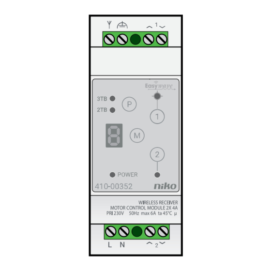
410-00352
Before installing the device, carefully read this operating manual.
1.
DESCRIPTION
The 410-00352 DIN rail receiver is used for control of tubular motors. Different modes are used for controlling
roller shutters and blinds.
1.1. Controlling roller shutters and blinds
1.1.1. ROLLER SHUTTER OPERATING MODES (R)
Roller shutter operating modes (R) generally carry out positioning commands immediately in self-maintained
mode. Pressing the transmitter button briefly is all that is needed to move to a position (for example to open or
close the roller shutter).
1.1.2. BLIND OPERATING MODES (J)
In blind operating modes (J), to adjust the slats, each positioning command is initially interpreted as a push
button command. That means, that the blind will only move for as long as the transmitter button is held down.
If the transmitter button is pressed for >1.6 seconds, the control system goes into self-maintained mode and
the blind moves independently to a position or an end point.
1.2. Lock mode
The lock mode allows the CLOSE direction of one or several outputs to be locked, therefore preventing accidental
lockout. To do this, a separate transmitter must be programmed with the corresponding operating mode. Only
transmitters with 2-button-operation (ON/OFF) can be used. If the lock mode is activated with the transmitter, the
output only travels in the OPEN direction. If an attempt is made to travel in the CLOSE direction, the command
is rejected and the LED for the corresponding channel flashes for 2 seconds.
1.3. Positioning
Roller shutters and blinds can both be programmed with up to three positions. These can then be specifically
approached with the relevant programmed transmitter. Positions are always approached from above to enable
maximum precision. To be able to move positions, a runtime measurement for the connected roller shutter (or
blind) is needed first.
1.4. Adjustable runtime
The runtimes for each output in OPEN and CLOSE directions are individually measured and saved. The factory
default setting is a runtime of 90 seconds. The maximum runtime that can be set is approximately 2 hours.
1.5. Adjustable reversing time
For blind operating mode (J), each output can be programmed with a separate reversing time. If the reversing
time has been programmed, after each STOP signal received during closing (CLOSE), the blind slats move in the
OPEN direction for the set amount of time. Also, each time the position is changed, the blind reverses as soon
as the position has been reached. So, the desired slat angle can be attained automatically after every position
change. In default factory settings the reversing mode is deactivated.
2.
INSTALLATION
The device is intended for installation on a standard DIN rail (35 x 7.5 mm).
1. Switch off the power supply.
2. Mount the 410-00352 onto the rail.
3. Connect the cables for the power supply and for the devices in accordance with the connection diagram.
L
230V~
N
PE
4. Switch on the supply voltage.
5. Program the receiver according to the operating manual.
In unfavourable environmental conditions, the external antenna 410-00359 can be used to improve wireless
reception (to be bought separately).
3.
OPERATION AND USE
The device shall only be operated at AC voltages of 230 V / 50 Hz. Operate the devices only with loads that do
not exceed the specified power limits (see § Specifications). This device is only intended for indoor use in dry
and dust-free rooms. This module may only be used as a wireless receiver for switching electrical devices. To
be operated with wireless transmitters following the Easywave protocol.
EN
3.1. Display
Display
Operating status
LED
GREEN
POWER
Power
Supply voltage is on, LED is lit
LED
RED
LED 3TB flashes when a wire-
3TB
3-button operation
less signal is detected
2TB
2-button operation
1
LED output 1 flashes Output 1 activated
2
LED output 2 flashes Output 2 activated
Digital display
Upon receiving a programmed
transmission code, the cor-
O...L
responding operating mode is
displayed for 2 s.
Operating
Operating status
Programming button
Mode button
Operate output 1 manually
Channel 1 button
(OPEN/CLOSE alternately)
Operate output 2 manually
Channel 2 button
(OPEN/CLOSE alternately)
Note: If you change the programming mode, all outputs are switched off, the HOLD function is deactivated, and
no control is possible during programming. If you return to operating mode, the outputs remain switched off.
3.2. Operation
3.2.1. 3-BUTTON OPERATION
In a 3-button operation (3TB), transmitter button A has the function OPEN (roller shutters/blinds are opened),
transmitter button B has the function CLOSE (roller shutters/blinds are closed) and buttons C and D (if present)
have the function STOP (movement is stopped).
For this operation, a transmitter with at least three connected buttons is necessary. Only one transmission button
must be programmed in the receiver. The code for additional buttons is assigned automatically.
3.2.2. 2-BUTTON OPERATION
In a 2-button operation (2TB), transmitter button A has the function OPEN (roller shutters/blinds are opened),
transmitter button B has the function CLOSE (roller shutters/blinds are closed). The movement is stopped by
pressing the button for the opposite direction.
For this operation, a transmitter with two connected buttons is sufficient. Only one transmission button must be
programmed in the receiver. The code for additional buttons is assigned automatically.
A
B
A
A
B
C
D
A
B
B
A
B
C
D
05-317
A
C
B
05-312
Programming mode
Displays the selected operation
Signals the programming or
delete mode
Displays the output selected for
programming
Displays the selected operating
mode
Programming mode
Start programming mode and
select an operation
Select an operating mode
Select output 1
Select output 2
A
A
C
C
B
B
D
K
05-318
410-00002
PM410-00352R20383
Werbung
Inhaltsverzeichnis

Verwandte Anleitungen für Niko 410-00352


Inhaltszusammenfassung für Niko 410-00352
-
Seite 13: Betrieb Und Verwendung
410-00352 Lesen Sie diese Betriebsanleitung vor der Montage sorgfältig. 3.1. Anzeige BESCHREIBUNG Der DIN-Schienen-Empfänger 410-00352 dient zur Steuerung von Rohrmotoren. Für die Steuerung von Rollläden und Jalousien werden verschiedene Modi verwendet. 1.1. Steuerung von Rollläden und Jalousien 1.1.1. ROLLLADEN-BETRIEBSARTEN (R) In den Rollladen-Betriebsarten (R) werden Positionierungsbefehle in der Regel sofort im autonomen Modus ausgeführt. - Seite 14 410-00352 3.3. Betriebsmodi Es sind mehrere Betriebsmodi einstellbar. In der folgenden Übersicht sind alle Betriebsmodi und ihre Funktion aufgeführt. Siehe § 4.1 für Informationen zum Programmieren eines Betriebsmodus. Betriebsmodus Beschreibung 3-Tastenbetrieb (3TB) 2-Tastenbetrieb (2TB) Sendertaste Sendertaste Standardsteuerung R 120 s Rollladenlaufzeit 120 Sekunden ÖFFNEN...
- Seite 15 Nach einem Reset beträgt die Standard-Umsteuerzeit 0 Sekunden. Sie können diesen Wert auch wiederherstellen, fänger betriebsbereit indem Sie eine Umsteuerzeitmessung durchführen, ohne die Jalousie zu bewegen. Wenn innerhalb von 30 Sekunden keine Taste gedrückt wird, schaltet der 410-00352 automatisch in Schritt Betrieb Taste drücken...
-
Seite 16: Technische Daten
410-00352 Wählen Sie die Betriebsart (OM 4, 5, 6, 8, BM-Nummer auf digitaler 9 oder A) Anzeige mehrmals 4...A Ausgang auswählen. Es kann nur ein Aus- LED1 oder LED2 und LED oder gang gewählt werden. Nach Bedarf ändern 3TB blinken... - Seite 21 This product complies with all of the relevant European guidelines and regulations. For radio equipment Niko llc declares that the radio equipment in this manual conforms with the 2014/53/EU directive. If applicable, the full text of the EU Declaration of Conformity can be found on www.niko.eu. CE-markering Dit product voldoet aan alle toepasselijke Europese richtlijnen en verordeningen.