Lika ROTACOD SMRA Serie Montageanleitung
Absolute bearingless encoders
Quicklinks
ROTACOD
Absolute bearingless encoders
Series
Complete documentation
available for download at www.lika.biz
Warning: encoders having order code ending with "/Sxxx" may have mechanical and electrical characteristics different from standard and be supplied with additional documentation for special connections (Technical Info).
Attenzione: gli encoder con codice di ordinazione finale "/Sxxx" possono avere caratteristiche meccaniche ed elettriche diverse dallo standard ed essere provvisti di documentazione aggiuntiva per cablaggi speciali (Technical info).
Achtung: Geräte, deren Bestellschlüssel mit der Kennung /Sxxx enden, können in ihren mech. und elektr. Eigenschaften vom Standard abweichen. Diese werden daher mit einer ergänzenden Dokumentation ausgeliefert (Technical info).
Atención: los encoders con código de pedido acabado en "/Sxxx" pueden tener características mecánicas y eléctricas diferentes a las básicas y documentación adicional relativa a conexiones especiales (Technical Info).
Attention: les codeurs avec code de commande terminant en "/Sxxx" peuvent avoir des caractéristiques mécaniques et électriques différentes du standard et documentation additionnelle pour les câblages spéciaux (Technical info).
EN
Mounting instructions
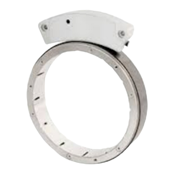
Mount the magnetic ring 2 on the motor shaft;
mount the locking ring 3 and fasten the whole assembly to the
motor shaft; tighten the bolts following the sequence.
Fix the sensor 1 using two cylinder head bolts M4 x 25 UNI5931;
the maximum distance between the sensor 1 and the magnetic
ring 2 is 1 ±0.2 mm (MRA/65 = 0.8 ±0.15 mm);
warning: mount the sensor 1 as shown in the Figures (see cable
outlet). The arrow indicates the standard counting direction (count
up information). We suggest using the optional mounting tool.
ES
Instrucciones de montaje
Montar el anillo magnético 2 en el eje del motor;
montar el anillo de fijación 3 y fijar los componentes al eje del
motor, fijar los tornillos siguiendo el orden indicado.
Fijar el sensor 1 mediante dos tornillos de cabeza cilíndrica tipo M4
x 25 UNI5931;
la distancia máxima entre el sensor 1 y el anillo magnético 2 es 1
±0,2 mm (MRA/65 = 0,8 ±0,15 mm);
advertencia: montar el sensor 1 como se muestra en las Figuras
(ver la salida del cable). La flecha indica el sentido de conteo
positivo (conteo ascendente). Se aconseja el uso del kit de montaje.
Signals
M12 8-pin
M8 cable
0Vdc
1
+Vdc *
2
Clock IN + / MA+
3
Clock IN - / MA-
4
Data OUT + / SLO+
5
Data OUT - / SLO-
6
Zero setting/Preset
7
Counting direction
8
Shielding
Case
Installation has to be carried out with power supply disconnected.
L'installazione deve essere eseguita in assenza di tensione.
Der Anschluss darf nur bei ausgeschalteter Versorgungsspannung erfolgen.
La instalación sólo debe ser efectuada en ausencia total de tensión.
Le montage du dispositif doit être effectué en absence totale de tension.
SMRA • MRA
IT
Inserire l'anello magnetico 2 sull'albero del motore;
inserire l'anello di serraggio 3, quindi fissare le parti all'albero del
motore stringendo le viti nell'ordine indicato.
Fissare il sensore 1 con due viti a testa cilindrica M4 x 25 UNI5931;
la distanza massima tra il sensore 1 e l'anello magnetico 2 è di 1
±0,2 mm (MRA/65 = 0,8 ±0,15 mm);
attenzione: montare il sensore 1 come mostrato nelle Figure (si veda
l'uscita cavo). La freccia indica la direzione di conteggio positiva
(conteggio crescente). Si consiglia l'utilizzo del tool di montaggio.
FR
Monter l'anneau magnétique 2 sur l'arbre moteur;
monter l'anneau de blocage 3 et fixer tout l'ensemble à l'arbre
moteur ; fermer les vis en suivant l'ordre indiqué.
Fixer le capteur 1 au moyen des deux vis avec tête cylindrique M4 x
25 UNI5931;
la distance maximum entre le capteur 1 et l'anneau magnétique 2
doit être de 1 ±0,2 mm (MRA/65 = 0,8 ± 0,15 mm);
attention: monter le capteur 1 comme indiqué dans les Figures (voir
la sortie du câble). La flèche indique la direction de comptage positif
(comptage augmentant). On conseille d'utiliser le kit de montage.
Electrical connections
Cavo M8
Kabel M8
Black
Nero
Schwarz
Red
Rosso
Rot
Yellow
Giallo
Gelb
Blue
Blu
Blau
Green
Verde
Grün
Orange
Arancione
Orange
White
Bianco
Weiß
Grey
Grigio
Grau
Shield
Calza
Schirm
Istruzioni di montaggio
Instructions de montage
Cable M8
Câble M8
Negro
Noir
OFF
Rojo
Rouge
Amarillo
Jaune
Azul
Bleu
Verde
Vert
ON
Anaranjado
Orange
(solid
Blanco
Blanc
red)
Gris
Gris
Malla
Blindage
* +Vdc according to the order code
SMRA-GG1-14 +Vdc = +5Vdc ± 5%
SMRA-GG2-14 +Vdc = +10Vdc +30Vdc
DE
Montagehinweise
Schieben Sie den Magnetring 2 auf die Motorwelle;
Setzen Sie den Befestigungsring 3 auf den Magnetring 2 und
befestigen Sie die gesamte Baugruppe auf der Motorwelle, in dem
Sie die Schrauben in der angezeigten Reihenfolge anziehen;
Befestigen Sie Geber 1 mit zwei M4 x 25 UNI5931 Schrauben;
Der Abstand zwischen Sensor 1 und dem Magnetring 2 darf maximal
1 ± 0,2 mm betragen (MRA/65 = 0,8 ±0,15 mm);
Achtung: Montieren Sie den Sensor 1 wie in der Zeichnung
angegeben (achten Sie auf den Kabelausgang). Der Pfeil zeigt die
Standardzählrichtung an (Hochzählen). Wie empfehlen, das
optionale Montagewerkzeug zu benutzen.
Diagnostic LED
Connector type
male frontal side
Proper operation, no active
maschio lato contatti
errors.
Aufsicht Stiftseite
macho lado contactos
Error signal:
mâle côté contacts
position calculation error,
invalid position value;
mounting error;
power supply is not as
required *;
EEPROM error.
M12 8-pin

Verwandte Anleitungen für Lika ROTACOD SMRA Serie


Inhaltszusammenfassung für Lika ROTACOD SMRA Serie
- Seite 1 Series Complete documentation available for download at www.lika.biz Warning: encoders having order code ending with "/Sxxx" may have mechanical and electrical characteristics different from standard and be supplied with additional documentation for special connections (Technical Info). Attenzione: gli encoder con codice di ordinazione finale “/Sxxx” possono avere caratteristiche meccaniche ed elettriche diverse dallo standard ed essere provvisti di documentazione aggiuntiva per cablaggi speciali (Technical info).
- Seite 2 SSI, Binary code, MSB aligned BG Cable length: L1 = 1 la Société Lika Electronic nie toute responsabilité pour tout dommage ou blessure que l'utilisateur peut encourir à la suite de la non-observance SSI, Gray code, MSB aligned GG m cable;...