Inhaltsverzeichnis
Werbung
Quicklinks
Version 1.0
Published October 2015
Copyright©2015 ASRock INC. All rights reserved.
Copyright Notice:
No part of this documentation may be reproduced, transcribed, transmitted, or
translated in any language, in any form or by any means, except duplication of
documentation by the purchaser for backup purpose, without written consent of
ASRock Inc.
Products and corporate names appearing in this documentation may or may not
be registered trademarks or copyrights of their respective companies, and are used
only for identification or explanation and to the owners' benefit, without intent to
infringe.
Disclaimer:
Specifications and information contained in this documentation are furnished for
informational use only and subject to change without notice, and should not be
constructed as a commitment by ASRock. ASRock assumes no responsibility for
any errors or omissions that may appear in this documentation.
With respect to the contents of this documentation, ASRock does not provide
warranty of any kind, either expressed or implied, including but not limited to
the implied warranties or conditions of merchantability or fitness for a particular
purpose.
In no event shall ASRock, its directors, officers, employees, or agents be liable for
any indirect, special, incidental, or consequential damages (including damages for
loss of profits, loss of business, loss of data, interruption of business and the like),
even if ASRock has been advised of the possibility of such damages arising from any
defect or error in the documentation or product.
This device complies with Part 15 of the FCC Rules. Operation is subject to the following
two conditions:
(1) this device may not cause harmful interference, and
(2) this device must accept any interference received, including interference that
may cause undesired operation.
CALIFORNIA, USA ONLY
The Lithium battery adopted on this motherboard contains Perchlorate, a toxic substance
controlled in Perchlorate Best Management Practices (BMP) regulations passed by the
California Legislature. When you discard the Lithium battery in California, USA, please
follow the related regulations in advance.
"Perchlorate Material-special handling may apply, see www.dtsc.ca.gov/hazardouswaste/
perchlorate"
ASRock Website: http://www.asrock.com
Werbung
Inhaltsverzeichnis

Verwandte Anleitungen für ASROCK Fatal1ty Z170 Professional Gaming i7 Serie


Inhaltszusammenfassung für ASROCK Fatal1ty Z170 Professional Gaming i7 Serie
- Seite 1 (including damages for loss of profits, loss of business, loss of data, interruption of business and the like), even if ASRock has been advised of the possibility of such damages arising from any defect or error in the documentation or product.
- Seite 2 The terms HDMI™ and HDMI High-Definition Multimedia Interface, and the HDMI logo are trademarks or registered trademarks of HDMI Licensing LLC in the United States and other countries. Manufactured under license under U.S. Patent Nos: 5,956,674; 5,974,380; 6,487,535; 7,003,467 & other U.S. and worldwide patents issued & pending. DTS, the Symbol, & DTS and the Symbol together is a registered trademark &...
- Seite 3 Fatal1ty Story Who knew that at age 19, I would be a World Champion PC gamer. When I was 13, I actually played competitive billiards in professional tournaments and won four or five games off guys who played at the highest level. I actually thought of making a career of it, but at that young age situations change rapidly.
- Seite 4 LIVIN’ LARGE Since my first big tournament wins, I have been a “Professional Cyberathlete”, traveling the world and livin’ large with lots of International media coverage on outlets such as MTV, ESPN and a 60 Minutes segment on CBS to name only a few. It's unreal - it's crazy. I’m living a dream by playing video games for a living.
-
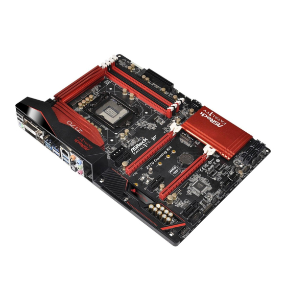
Seite 5: Motherboard-Layout
Fatal1ty Z170 Professional Gaming i7 Series Motherboard Layout CPU_FAN1 CHA_FAN4 CPU_FAN2 CLRCBTN1 ATX12V1 Power Reset USB 3.1 T: USB31_TA_1 B: USB31_TC_1 USB 3.0 Top: T: USB3 RJ-45 B: USB4 USB 3.0 Top: T: USB1 RJ-45 B: USB2 CHA_FAN2 CHA_FAN3 FATAL CHA_FAN1 CT14 CT13... - Seite 6 No. Description ATX 12V Power Connector (ATX12V1) CPU Fan Connector (CPU_FAN1) CPU Fan Connector (CPU_FAN2) 2 x 288-pin DDR4 DIMM Slots (DDR4_A1, DDR4_B1) 2 x 288-pin DDR4 DIMM Slots (DDR4_A2, DDR4_B2) Chassis Fan Connector (CHA_FAN4) Clear CMOS Button (CLRCBTN1) Power Switch (PWRBTN1) Reset Switch (RSTBTN1) ATX Power Connector (ATXPWR1) USB 3.0 Header (USB3_7_8)
- Seite 7 Fatal1ty Z170 Professional Gaming i7 Series 1.4 I/O Panel No. Description No. Description USB 2.0 Ports (USB1) Microphone (Pink) Fatal1ty Mouse Port (USB2) Optical SPDIF Out Port DVI-D Port USB 3.0 Ports (USB3_12) LAN RJ-45 Port (Intel® I219V)* USB 3.0 Ports (USB3_34) LAN RJ-45 Port (Intel®...
- Seite 8 * There are two LEDs on each LAN port. Please refer to the table below for the LAN port LED indications. ACT/LINK LED SPEED LED LAN Port Activity / Link LED Speed LED Status Description Status Description No Link 10Mbps connection Blinking Data Activity Orange...
-
Seite 9: Package Contents
If you require technical support related to this mother- board, please visit our website for specific information about the model you are using. You may find the latest VGA cards and CPU support list on ASRock’s website as well. ASRock website http://www.asrock.com. - Seite 10 Celeron® Processors (Socket 1151) • Digi Power design • 12 Power Phase design • Supports Intel® Turbo Boost 2.0 Technology • Supports Intel® K-Series unlocked CPUs • Supports ASRock BCLK Full-range Overclocking • Supports ASRock Hyper BCLK Engine ® Chipset • Intel...
- Seite 11 • 7.1 CH HD Audio with Content Protection (Realtek ALC1150 Audio Codec) • Premium Blu-ray Audio support • Supports Surge Protection (ASRock Full Spike Protection) • Supports Purity Sound - Nichicon Fine Gold Series Audio Caps - 115dB SNR DAC with Differential Amplifier - TI®...
- Seite 12 • 1 x HDMI Port • 1 x DisplayPort 1.2 • 1 x Optical SPDIF Out Port • 1 x USB 2.0 Port (Supports ESD Protection (ASRock Full Spike Protection)) • 1 x Fatal1ty Mouse Port (USB 2.0) (Supports ESD Protection (ASRock Full Spike Protection)) • 1 x USB 3.1 Type-A Port (10 Gb/s) (ASMedia ASM1142)
- Seite 13 • 3 x USB 2.0 Headers (Support 6 USB 2.0 ports) (Supports ESD Protection (ASRock Full Spike Protection)) • 2 x USB 3.0 Headers (Support 4 USB 3.0 ports) (ASMedia ASM1074 hub) (Supports ESD Protection (ASRock Full Spike Protection)) • 1 x Dr. Debug with LED • 1 x Power Switch with LED...
- Seite 14 * To install Windows® 7 OS, a modified installation disk with xHCI drivers packed into the ISO file is required. Please refer to page 180 for more detailed instructions. * For the updated Windows® 10 driver, please visit ASRock’s website for details: http://www.asrock.com Certifica- • FCC, CE, WHQL...
- Seite 15 Fatal1ty Z170 Professional Gaming i7 Series Chapter 2 Installation This is an ATX form factor motherboard. Before you install the motherboard, study the configuration of your chassis to ensure that the motherboard fits into it. Pre-installation Precautions Take note of the following precautions before you install motherboard components or change any motherboard settings.
-
Seite 16: Installing The Cpu
2.1 Installing the CPU 1. Before you insert the 1151-Pin CPU into the socket, please check if the PnP cap is on the socket, if the CPU surface is unclean, or if there are any bent pins in the socket. Do not force to insert the CPU into the socket if above situation is found. - Seite 17 Fatal1ty Z170 Professional Gaming i7 Series...
- Seite 18 Please save and replace the cover if the processor is removed. The cover must be placed if you wish to return the motherboard for after service.
- Seite 19 Fatal1ty Z170 Professional Gaming i7 Series 2.2 Installing the CPU Fan and Heatsink...
- Seite 20 2.3 Installing Memory Modules (DIMM) This motherboard provides four 288-pin DDR4 (Double Data Rate 4) DIMM slots, and supports Dual Channel Memory Technology. 1. For dual channel configuration, you always need to install identical (the same brand, speed, size and chip-type) DDR4 DIMM pairs. 2.
- Seite 21 Fatal1ty Z170 Professional Gaming i7 Series...
- Seite 22 2.4 Expansion Slots (PCI Express Slots) There are 6 PCI Express slots and 1 mini-PCI Express slot on the motherboard. Before installing an expansion card, please make sure that the power supply is switched off or the power cord is unplugged. Please read the documentation of the expansion card and make necessary hardware settings for the card before you start the installation.
- Seite 23 Fatal1ty Z170 Professional Gaming i7 Series 2.5 Jumpers Setup The illustration shows how jumpers are setup. When the jumper cap is placed on the pins, the jumper is “Short”. If no jumper cap is placed on the pins, the jumper is “Open”.
- Seite 24 2.6 Onboard Headers and Connectors Onboard headers and connectors are NOT jumpers. Do NOT place jumper caps over these headers and connectors. Placing jumper caps over the headers and connectors will cause permanent damage to the motherboard. System Panel Header Connect the power PLED+ PLED-...
- Seite 25 Fatal1ty Z170 Professional Gaming i7 Series Power LED and Speaker Please connect the SPEAKER DUMMY Header chassis power LED and DUMMY (7-pin SPK_PLED1) the chassis speaker to this (see p.1, No. 24) header. PLED+ PLED+ PLED- Serial ATA3 Connectors These ten SATA3 (SATA3_0_2: connectors support SATA see p.1, No.
- Seite 26 Serial ATA Express Please connect either Connectors SATA or PCIe storage (SATA_EXP_0: devices to these see p.1, No. 17) connectors. (SATA_EXP_1: *SATA_EXP0 is shared see p.1, No. 18) with the SATA3_0, (SATA_EXP_2: SATA3_1 and the M2_1; see p.1, No. 23) SATA_EXP1 is shared with the SATA3_2, SATA3_3 and the M2_2;...
- Seite 27 Fatal1ty Z170 Professional Gaming i7 Series 1. High Definition Audio supports Jack Sensing, but the panel wire on the chassis must sup- port HDA to function correctly. Please follow the instructions in our manual and chassis manual to install your system. 2.
- Seite 28 ATX Power Connector This motherboard pro- (24-pin ATXPWR1) vides a 24-pin ATX power (see p.1, No. 10) connector. To use a 20-pin ATX power supply, please plug it along Pin 1 and Pin ATX 12V Power This motherboard pro- Connector vides an 8-pin ATX 12V (8-pin ATX12V1) power connector.
-
Seite 29: Smart Switches
Fatal1ty Z170 Professional Gaming i7 Series 2.7 Smart Switches The motherboard has four smart switches: Power Switch, Reset Switch, Clear CMOS Switch and BIOS Selection Switch, allowing users to quickly turn on/off the system, reset the system, clear the CMOS values or switch between BIOS A and BIOS B. Power Switch Power Switch allows users (PWRBTN) - Seite 30 2.8 Dr. Debug Dr. Debug is used to provide code information, which makes troubleshooting even easier. Please see the diagrams below for reading the Dr. Debug codes. Code Description Please check if the CPU is installed correctly and then clear CMOS.
- Seite 31 Fatal1ty Z170 Professional Gaming i7 Series Problem related to USB devices. Please try removing all USB devices. Problem related to memory. Please re-install the CPU and memory then clear CMOS. If the problem still exists, please install only one memory module or try using other memory modules.
- Seite 32 2.9 M.2_SSD (NGFF) Module Installation Guide The M.2, also known as the Next Generation Form Factor (NGFF), is a small size and versatile card edge connector that aims to replace mPCIe and mSATA. The Ultra M.2 Sockets support M.2 PCI Express module up to Gen3 x4 (32 Gb/s). * M2_1, SATA3_0, SATA3_1 and SATA_EXP0 share lanes.
- Seite 33 Fatal1ty Z170 Professional Gaming i7 Series Step 3 Move the standoff based on the module type and length. The standoff is placed at the nut location D by default. Skip Step 3 and 4 and go straight to Step 5 if you are going to use the default nut.
- Seite 34 SATA3 2280 TM8PS4256GMC105 Team 256GB SATA3 2242 TM4PS4256GMC105 Transcend 256GB SATA3 2242 TS256GMTS400 Transcend 512GB SATA3 2280 TS512GMTS800 Transcend 512GB SATA3 2260 TS512GMTS600 For the latest updates of M.2_SSD (NFGG) module support list, please visit our website for details: http://www.asrock.com...
-
Seite 35: Einleitung
Inhalt dieser Dokumentation ohne Ankündigung geändert werden. Falls diese Dokumentation irgendwelchen Änderungen unterliegt, wird die aktualisierte Version ohne weitere Hinweise auf der ASRock-Webseite zur Verfügung gestellt. Sollten Sie technische Hilfe in Bezug auf dieses Motherboard benötigen, erhalten Sie auf unserer Webseite spezifischen Informationen über das von Ihnen verwendete Modell. -
Seite 36: Technische Daten
Prozessor Celeron® der 6. Generation (Sockel 1151) • Digipower-Design • 12-Leistungsphasendesign • Unterstützt Intel® Turbo Boost 2.0-Technologie • Unterstützt CPUs mit freiem Multiplikator der Intel® K-Serie • Unterstützt ASRock BCLK-Übertaktung (voller Bereich) • Unterstützt ASRock-Hyper-BCLK-Engine ® • Intel Z170 Chipsatz • Dualkanal-DDR4-Speichertechnologie... - Seite 37 DVI-D-, HDMI- und DisplayPort 1.2-Ports Audio • 7.1-Kanal-HD-Audio mit Inhaltsschutz (Realtek ALC1150-Audiocodec) • Erstklassige Blu-ray-Audiounterstützung • Unterstützt Überspannungsschutz (ASRock Full Spike Protection) • Unterstützt Purity Sound - Nichicon-Audiokappen der Fine Gold-Serie - 115-dB-SRV-DAC mit Differentialverstärker - TI® NE5532 – erstklassiger Headset-Verstärker (unterstützt Headsets mit bis zu 600 Ohm)
- Seite 38 • 1 x USB 2.0-Port (unterstützt Schutz gegen elektrostatische Entladung (ASRock Full Spike Protection)) • 1 x Fatal1ty-Mausport (USB 2.0) (unterstützt Schutz gegen elektrostatische Entladung (ASRock Full Spike Protection)) • 1 x USB 3.1-Typ-A-Port (10 Gb/s) (ASMedia ASM1142) (unterstützt Schutz gegen elektrostatische Entladung (ASRock Full Spike Protection)) • 1 x USB 3.1-Typ-C-Port (10 Gb/s) (ASMedia ASM1142)
-
Seite 39: Anschluss
• 1 x Audioanschluss an Frontblende • 1 x Thunderbolt-Erweiterungskartenanschluss • 3 x USB 2.0-Stiftleisten (unterstützen 6 USB 2.0-Ports) (unterstützt Schutz gegen elektrostatische Entladung (ASRock Full Spike Protection)) • 2 x USB 3.0-Stiftleisten (unterstützen 4 USB 3.0-Ports) (ASMedia ASM1074-Hub) (unterstützt Schutz gegen elektrostatische Entladung (ASRock Full Spike Protection)) • 1 x Dr. -
Seite 40: Hardware-Überwachung
• ErP/EuP ready (ErP/EuP ready-Netzteil erforderlich) * Detaillierte Produktinformationen finden Sie auf unserer Webseite: http://www.asrock.com Bitte beachten Sie, dass mit einer Übertaktung, zu der die Anpassung von BIOS- Einstellungen, die Anwendung der Untied Overclocking Technology oder die Nutzung von Übertaktungswerkzeugen von Drittanbietern zählen, bestimmte Risiken verbunden sind. -
Seite 41: Jumpereinstellung
Fatal1ty Z170 Professional Gaming i7 Series 1.3 Jumpereinstellung Die Abbildung zeigt, wie die Jumper eingestellt werden. Wenn die Jumper-Kappe auf den Kontakten angebracht ist, ist der Jumper „kurzgeschlossen“. Wenn keine Jumper- Kappe auf den Kontakten angebracht ist, ist der Jumper „offen“. Die Abbildung zeigt einen 3-poligen Jumper, dessen Kontakt 1 und Kontakt 2 „kurzgeschlossen“... -
Seite 42: Integrierte Stiftleisten Und Anschlüsse
1.4 Integrierte Stiftleisten und Anschlüsse Integrierte Stiftleisten und Anschlüsse sind KEINE Jumper. Bringen Sie KEINE Jumper-Kappen an diesen Stiftleisten und Anschlüssen an. Durch Anbringen von Jumper-Kappen an diesen Stiftleisten und Anschlüssen können Sie das Motherboard dauerhaft beschädigen. Systemblende-Stiftleiste Verbinden Sie PLED+ PLED- (9-polig, PANEL1) - Seite 43 Fatal1ty Z170 Professional Gaming i7 Series Betrieb-LED- und Bitte verbinden Sie SPEAKER DUMMY Lautsprecher-Stiftleiste die Betrieb-LED des DUMMY (7-polig, SPK_PLED1) Gehäuses und den (siehe S. 1, Nr. 24) Gehäuselautsprecher mit dieser Stiftleiste. PLED+ PLED+ PLED- Serial-ATA-III-Anschlüsse Diese zehn SATA-III- (SATA3_0_2: Anschlüsse unterstützen siehe S.
- Seite 44 Serial-ATA-Express- Bitte verbinden Sie Anschlüsse entweder SATA- oder (SATA_EXP_0: PCIe-Speichergeräte mit siehe S. 1, Nr. 17) diesen Anschlüssen. (SATA_EXP_1: *SATA_EXP0 wird siehe S. 1, Nr. 18) gemeinsam mit SATA3_0, (SATA_EXP_2: SATA3_1 und M2_1 siehe S. 1, Nr. 23) genutzt; SATA_EXP1 wird gemeinsam mit SATA3_2, SATA3_3 und M2_2 genutzt;...
- Seite 45 Fatal1ty Z170 Professional Gaming i7 Series 1. High Definition Audio unterstützt Anschlusserkennung, der Draht am Gehäuse muss dazu jedoch HDA unterstützt. Bitte befolgen Sie zum Installieren Ihres Systems die Anweisungen in unserer Anleitung und der Anleitung zum Gehäuse. 2. Bei Nutzung eines AC’97-Audiopanels dieses bitte anhand folgender Schritte an der Audiostiftleiste der Frontblende installieren: A.
- Seite 46 ATX-Netzanschluss Dieses Motherboard (24-polig, ATXPWR1) bietet einen 24-poligen (siehe S. 1, Nr. 10) ATX-Netzanschluss. Bitte schließen Sie es zur Nutzung eines 20-poligen ATX- Netzteils entlang Kontakt 1 und Kontakt 13 an. ATX-12-V-Netzanschluss Dieses Motherboard bietet (8-polig, ATX12V1) einen 8-poligen ATX-12-V- (siehe S.
- Seite 47 Fatal1ty Z170 Professional Gaming i7 Series 1.5 Intelligente Schalter Das Motherboard hat vier intelligente Schalter: Ein-/Ausschalter, Reset-Schalter, CMOS-löschen-Schalter und BIOS-Auswahlschalter; ermöglichen Nutzern schnellen Ein-/Ausschalten des Systems, Rücksetzung des Systems, Löschung der CMOS-Werte oder Umschalten zwischen BIOS A und BIOS B. Ein-/Ausschalter Mit dem Ein-/Ausschalter kann (PWRBTN)
-
Seite 48: Contenu De L'emballage
à modification sans préavis. En cas de modifications du présent document, la version mise à jour sera disponible sur le site Internet ASRock sans notification préalable. Si vous avez besoin d’une assistance technique pour votre carte mère, veuillez visiter notre site Internet pour plus de détails sur le modèle que vous utilisez. - Seite 49 • Prend en charge la technologie Intel® Turbo Boost 2.0 • Prend en charge les processeurs débloqués de la série K Intel® • Prend en charge l’ o verclocking ASRock BCLK Full-range • Prend en charge le moteur ASRock Hyper BCLK ®...
- Seite 50 Audio Realtek ALC1150) • Compatible audio Blu-ray Premium • Protection contre les surtensions (Protection complète contre les pics ASRock) • Prend en charge Purity Sound - Couvercles audio série en or fin Nichicon - 115dB SNR DAC avec amplificateur différentiel - Amplificateur de casque TI®...
- Seite 51 • 1 x port sortie optique SPDIF • 1 x port USB 2.0 (Protection contre les décharges électrostatiques (Protection complète contre les pics ASRock)) • 1 x port souris Fatal1ty (USB 2.0) (Protection contre les décharges électrostatiques (Protection complète contre les pics ASRock)) • 1 port USB 3.1 type A (10 Gb/s) (ASMedia ASM1142)
- Seite 52 • 3 x sockets Ultra M.2, prend en charge les modules M.2 SATA3 6,0 Gb/s et M.2 PCI Express jusqu'à Gen3 x4 (32 Gb/s) * Prend en charge le kit ASRock U.2 • 1 x embase pour port COM Connecteur • 1 x embase TPM...
- Seite 53 • FCC, CE, WHQL • ErP/EuP Ready (alimentation ErP/EuP ready requise) * pour des informations détaillées de nos produits, veuillez visiter notre site : http://www.asrock.com Il est important de signaler que l’ o vercloking présente certains risques, incluant des modifications du BIOS, l’ a pplication d’une technologie d’ o verclocking déliée et l’utilisation d’ o utils d’...
- Seite 54 1.3 Configuration des cavaliers (jumpers) L’illustration ci-dessous vous renseigne sur la configuration des cavaliers (jumpers). Lorsque le capuchon du cavalier est installé sur les broches, le cavalier est « court- circuité ». Si le capuchon du cavalier n’ e st pas installé sur les broches, le cavalier est « ouvert ».
- Seite 55 Fatal1ty Z170 Professional Gaming i7 Series 1.4 Embases et connecteurs de la carte mère Les embases et connecteurs situés sur la carte NE SONT PAS des cavaliers. Ne placez JAMAIS de capuchons de cavaliers sur ces embases ou connecteurs. Placer un capuchon de cavalier sur ces embases ou connecteurs endommagera irrémédiablement votre carte mère.
- Seite 56 Prise DEL d’alimentation Veuillez brancher la DEL SPEAKER DUMMY et haut-parleur d'alimentation du châssis DUMMY (SPK_PLED1 à 7 broches) et le haut-parleur du (voir p.1, No. 24) châssis sur ce connecteur. PLED+ PLED+ PLED- Connecteurs Serial ATA3 Ces dix connecteurs (SATA3_0_2: SATA3 sont compatibles voir p.1, No.
- Seite 57 Fatal1ty Z170 Professional Gaming i7 Series Connecteurs série ATA Veuillez connecter des Express périphériques de stockage (SATA_EXP_0: SATA ou PCIe à ces voir p.1, No. 17) connecteurs. (SATA_EXP_1: *SATA_EXP0 est partagé voir p.1, No. 18) avec SATA3_0, SATA3_1 (SATA_EXP_2: et M2_1 ; SATA_EXP1 est voir p.1, No.
- Seite 58 1. L’ a udio haute définition prend en charge la technologie Jack Sensing (détection de la fiche), mais le panneau grillagé du châssis doit être compatible avec la HDA pour fonctionner correctement. Veuillez suivre les instructions figurant dans notre manuel et dans le manuel du châssis pour installer votre système.
- Seite 59 Fatal1ty Z170 Professional Gaming i7 Series Connecteur d’alimentation Cette carte mère est dotée d’un connecteur d’alimentation (ATXPWR1 à 24 broches) ATX à 24 broches. Pour utiliser (voir p.1, No. 10) une alimentation ATX à 20 broches, veuillez effectuer les branchements sur la Broche 1 et la Broche 13.
- Seite 60 1.5 Boutons intelligents La carte mère est équipée de quatre boutons intelligents : Bouton de mise en marche, bouton de réinitialisation, bouton d’ e ffacement CMOS et bouton de sélecteur de BIOS qui permettent aux utilisateurs d’allumer/éteindre le système, de réinitialiser le système, d’...
-
Seite 61: Contenuto Della Confezione
Web di ASRock senza ulteriore preavviso. Per il supporto tecnico correlato a questa scheda madre, visitare il nostro sito Web per informazioni specifiche relative al modello attualmente in uso. - Seite 62 • Potenza a 12 fasi • Supporta la tecnologia Intel® Turbo Boost 2.0 • Supporto di CPU unlocked Intel® K-Series • Supporta gamma completa overclocking BCLK ASRock • Compatibile con il motore ASRock Hyper BCLK ® Chipset • Intel Z170 Memoria • Tecnologia memoria DDR4 Dual Channel...
- Seite 63 • Audio HD a 7,1 canali con Content Protection (codec audio Realtek ALC1150) • Supporto audio Blu-ray Premium • Supporto protezione da sovratensione (protezione completa ASRock dai picchi di corrente) • Supporto di Purity Sound - Cappucci audio Nichicon serie Fine Gold - 115dB SNR DAC con amplificatore differenziale - TI®...
- Seite 64 • 1 x Giga PHY Intel® I219V, 1 x GigaLAN Intel® I211AT • Supporta Wake-On-LAN • Supporto la protezione da fulmini/scariche elettrostatiche (ESD) (protezione completa ASRock dai picchi di corrente) • Supporto di Dual LAN con Teaming • Supporta Energy Efficient Ethernet 802.3az • Supporta PXE...
- Seite 65 ASRock dai picchi di corrente)) • 2 x Collettori USB 3.0 (supporto di 4 porte USB 3.0) (hub ASMedia ASM1074) (supporto protezione da scariche elettrostatiche (ESD) (protezione completa ASRock dai picchi di corrente)) • 1 x Dr. Debug con LED • 1 x interruttore d’alimentazione con LED...
- Seite 66 * Per installare Windows® 7, è necessario un disco di installazione modificato con i driver xHCI integrati nel file ISO. Fare riferi- mento a pagina 180 per altre istruzioni dettagliate. * Per il driver aggiornato di Windows® 10, visitare il sito ASRock all’indirizzo: http://www.asrock.com Certifi- • FCC, CE, WHQL...
- Seite 67 Fatal1ty Z170 Professional Gaming i7 Series 1.3 Impostazione jumper L'illustrazione mostra in che modo vengono impostati i jumper. Quando il cappuccio del jumper è posizionato sui pin, il jumper è "cortocircuitato". Se sui pin non è posizionato alcun cappuccio del jumper, il jumper è "aperto". L'illustrazione mostra un jumper a 3 pin i cui pin1 e pin2 sono "cortocircuitati"...
- Seite 68 1.4 Header e connettori sulla scheda Gli header e i connettori sulla scheda NON sono jumper. NON posizionare cappucci del jumper su questi header e connettori. Il posizionamento di cappucci del jumper su header e connettori provocherà danni permanenti alla scheda madre. Header sul pannello del Collegare l'interruttore PLED+...
- Seite 69 Fatal1ty Z170 Professional Gaming i7 Series Connettore LED Collegare i LED SPEAKER DUMMY alimentazione e alimentazione e DUMMY altoparlante l’altoparlante a questo (SPK_PLED1 7 pin) connettore. (vedere pag. 1, n. 24) PLED+ PLED+ PLED- Connettori Serial ATA3 Questi dieci connettori (SATA3_0_2: SATA3 supportano cavi vedere pag.
- Seite 70 Connettori Serial ATA Collegare i dispositivi Express d’archiviazione SATA o (SATA_EXP_0: PCIe a questi connettori. vedere pag.1, n. 17) * SATA_EXP0 è condiviso (SATA_EXP_1: con SATA3_0, SATA3_1 vedere pag.1, n. 18) e M2_1; SATA_EXP1 è (SATA_EXP_2: condiviso con SATA3_2, vedere pag.1, n. 23) SATA3_3 e M2_2;...
- Seite 71 Fatal1ty Z170 Professional Gaming i7 Series 1. L'audio ad alta definizione supporta le funzioni Jack sensing, ma il filo del pannello sullo chassis deve supportare HDA per funzionare correttamente. Seguire le istruzioni presenti nel nostro manuale e nel manuale dello chassis per installare il sistema. 2.
- Seite 72 Connettore di Questa scheda madre è dotata di alimentazione ATX un connettore di alimentazione (ATXPWR1 a 24 pin) ATX a 24 pin. Per utilizzare (vedere pag. 1, n. 10) un'alimentazione ATX a 20 pin, collegarla lungo il pin 1 e il pin 13.
- Seite 73 Fatal1ty Z170 Professional Gaming i7 Series 1.5 Interruttori intuitivi La scheda madre è dotata di quattro interruttori intuitivi: Interruttore d’alimentazione, interruttore di ripristino, interruttore Clear CMOS ed interruttore di selezione BIOS che consentono di accendere/spegnere rapidamente il sistema, ripristinare il sistema, cancellare i valori CMOS oppure di cambiare tra BIOS A e BIOS B.
-
Seite 74: Contenido Del Paquete
Si esta documentación sufre alguna modificación, la versión actualizada estará disponible en el sitio web de ASRock sin previo aviso. Si necesita asistencia técnica relacionada con esta placa base, visite nuestro sitio web para obtener información específica sobre el modelo que esté... - Seite 75 (memoria de un solo canal). * Para obtener más información, consulte la lista de memorias compatibles en el sitio web de ASRock. (http://www.asrock.com/) • Capacidad máxima de la memoria del sistema: 64GB • Admite Perfil de memoria extremo de Intel® (XMP) 2.0 • Contacto 15μ...
- Seite 76 ALC1150 Audio Codec) • Compatible con audio Blu-ray Premium • Compatible con protección por sobretensión (protección ASRock Full Spike) • Compatible con Purity Sound - Tapas de audio Nichion de la serie Fine Gold - 115dB SNR DAC con amplificador diferencial - Amplificador de auriculares de alta calidad TI®...
- Seite 77 (protección ASRock Full Spike)) • 1 puerto de ratón Fatal1ty (USB 2.0) (compatible con protección contra electricidad estática (protección ASRock Full Spike)) • 1 x Puerto USB 3.1 Tipo A Port (10 Gb/s) (ASMedia ASM1142) (admite protección ESD (protección total contra picos)) • 1 x Puerto USB 3.1 Tipo C (10 Gb/s) (ASMedia ASM1142)
- Seite 78 (protección ASRock Full Spike)) • 2 cabezales USB 3.0 (compatible con 4 puertos USB 3.0) (concentrador ASMedia ASM1074AE) (compatible con protección contra electricidad estática (protección ASRock Full Spike)) • 1 Dr. Debug con indicador LED • 1 interruptor de alimentación con indicador LED • 1 interruptor de reseteo con indicador LED...
- Seite 79 • Compatible con ErP/EuP (requiere toma de alimentación compatible con ErP/EuP) * Para obtener más información acerca del producto, visite nuestro sitio web: http://www.asrock.com Tenga en cuenta que existen ciertos riesgos relacionados con el overclocking (sobreaceleración), incluyendo el ajuste de la configuración del BIOS, aplicando la Tecnología overcloking no vinculada o utilizando las herramientas de overclocking de tercera parte.
- Seite 80 1.3 Instalación de los puentes La instalación muestra cómo deben instalarse los puentes. Cuando la tapa de puente se coloca en los pines, el puente queda “Corto”. Si no coloca la tapa de puente en los pines, el puente queda “Abierto”. La ilustración muestra un puente de 3 pines cuyo pin 1 y pin 2 son “Cortos”...
- Seite 81 Fatal1ty Z170 Professional Gaming i7 Series 1.4 Conectores y cabezales incorporados Los cabezales y conectores incorporados NO son puentes. NO coloque tapas de puente sobre estos cabezales y conectores. Si coloca tapas de puente sobre los cabezales y conectores dañará de forma permanente la placa base.
- Seite 82 LED de alimentación y Conecte el LED de SPEAKER DUMMY base de conexiones para la alimentación del chasis y DUMMY altavoz el altavoz del chasis a esta (SPK_PLED1 de 7 base de conexiones. contactos) PLED+ (consulte la pág.1, N.º 24) PLED+ PLED- Conectores Serie ATA3...
- Seite 83 Fatal1ty Z170 Professional Gaming i7 Series Conectores Serial ATA Enchufe los dispositivos de Express almacenamiento SATA o (SATA_EXP_0: PCIe a estos conectores. consulte la pág.1, N.º 17) *SATA_EXP0 se comparte (SATA_EXP_1: con SATA3_0, SATA3_1 consulte la pág.1, N.º 18) y M2_1; SATA_EXP1 se (SATA_EXP_2: comparte con SATA3_2, consulte la pág.1, N.º...
- Seite 84 1. El Audio de Alta Definición (HDA, en inglés) es compatible con el método de sensor de conectores, sin embargo, el cable del panel del chasis deberá ser compatible con HDA para que pueda funcionar correctamente. Siga las instrucciones que se indican en nuestro manual y en el manual del chasis para instalar su sistema.
- Seite 85 Fatal1ty Z170 Professional Gaming i7 Series Conector de alimentación Esta placa base contiene un conector de alimentación ATX (ATXPWR1 de 24 pines) de 24 pines. Para utilizar una (consulte la pág.1, N.º 10) toma de alimentación ATX de 20 pines, conéctela en los Pines del 1 al 13.
- Seite 86 1.5 Interruptores inteligentes La placa base contiene cuatro interruptores inteligentes: Interruptor de alimentación, Interruptor de restablecimiento, Interruptor de borrado de CMOS e Interruptor de selección de BIOS, lo que permite a los usuarios encender y apagar el sistema, restablecer el sistema, borrar los valores de la CMOS o cambiar entre la BIOS A y la BIOS B.
-
Seite 87: Комплект Поставки
• Краткое руководство по установке ASRock Fatal1ty Z170 Professional Gaming i7 Series • Компакт-диск с ПО для платы ASRock Fatal1ty Z170 Professional Gaming i7 Series • 4 х кабеля передачи данных Serial ATA (SATA) (приобретаются отдельно) • 1 х экран панели с портами ввода-вывода... - Seite 88 • Digi Power design • Система питания 12 • Поддержка технологии Intel® Turbo Boost 2.0 • Поддержка процессоров Intel® серии K с разблокированным множителем • Поддержка полного разгона процессора ASRock BCLK • Поддерживает систему ASRock Hyper BCLK ® • Intel Z170 Чипсет...
- Seite 89 • 7,1-канальный звук высокой четкости HD Audio с защитой данных (аудиокодек Realtek ALC1150) • Поддержка Premium Blu-ray Audio • Защита от перенапряжения (ASRock Full Spike Protection) • Поддержка Purity Sound - Конденсаторы для аудиосистем серии Nichicon Fine Gold - 115 дБ SNR DAC с дифференциальным усилителем...
- Seite 90 • 1 x Giga PHY Intel® I219V, 1 x GigaLAN Intel® I211AT • Поддержка Wake-On-LAN • Молниезащита и защита электростатического напряжения (ASRock Full Spike Protection) • Поддержка двух ЛВС с функцией группирования • Поддержка Energy Efficient Ethernet 802.3az • Поддержка PXE • 1 x PS/2 для...
- Seite 91 • 3 x Ultra M.2 Socket, поддержка модуля M.2 SATA3 со скоростью обмена данными 6,0 ГБ/с и модуля M.2 PCI Express до версии Gen3 x4 (32 ГБ/с) * Поддержка комплекта ASRock U.2 • 1 x колодка СОМ-порта Разъемы • 1 x Колодка ТРМ...
- Seite 92 • FCC, CE, WHQL • Совместимость с ErP/EuP (необходим блок питания, соответствующий стандарту ErP/EuP) * Для получения дополнительной информации об изделии посетите наш веб-сайт: http://www.asrock.com Следует учитывать, что разгон процессора, включая изменение настроек BIOS, применение технологии Untied Overclocking Technology и использование инструментов...
- Seite 93 Fatal1ty Z170 Professional Gaming i7 Series 1.3 Установка перемычек Установка перемычек показана на рисунке. При установке колпачковой перемычки на контакты перемычка «замкнута». Если колпачковая перемычка на контакты не установлена, перемычка «разомкнута». На рисунке показана 3-контактная перемычка с замкнутыми контактами 1 и 2 при установке на них колпачковой...
- Seite 94 1.4 Колодки и разъемы, расположенные на материнской плате Расположенные на материнской плате колодки и разъемы перемычками НЕ являются. НЕ устанавливайте на эти колодки и разъемы колпачковые перемычки. Установка колпачковых перемычек на эти колодки и разъемы может вызвать неустранимое повреждение материнской платы. PLED+ Колодка...
- Seite 95 Fatal1ty Z170 Professional Gaming i7 Series Колодка светодиодного Предназначена SPEAKER DUMMY индикатора питания и для подключения DUMMY динамика корпуса светодиодного (7-контактная, SPK_ индикатора питания и PLED1) динамика корпуса. PLED+ (См. стр. 1, № 24) PLED+ PLED- Разъемы Serial ATA3 Эти десять (SATA3_0_2: разъемов...
- Seite 96 Разъемы SATA Express К данным разъемам (SATA_EXP_0: подключаются см. стр.1, № 17) накопители SATA или (SATA_EXP_1: PCIe. см. стр.1, № 18) *Разъем SATA_EXP0 (SATA_EXP_2: используется вместе с см. стр.1, № 23) SATA3_0, SATA3_1 и M2_1; разъем SATA_ EXP1 используется вместе с SATA3_2, SATA3_3 и...
- Seite 97 Fatal1ty Z170 Professional Gaming i7 Series 1. Аудиосистема высокого разрешения поддерживает функцию распознавания разъема, но для е правильной работы необходимо, чтобы провод панели корпуса поддерживал передачу сигналов HDA. Инструкции по установке системы см. в этом руководстве и руководстве на корпус. 2.
- Seite 98 Разъем питания АТХ Эта материнская плата (24-контактный, снабжена 24-контактным ATXPWR1) разъемом питания АТХ. Чтобы (См. стр. 1, № 10) использовать 20-контактный разъем питания ATX, подключите его вдоль контакта 1 и контакта 13. Разъем питания АТХ Эта материнская плата 12 В снабжена...
- Seite 99 Fatal1ty Z170 Professional Gaming i7 Series 1.5 Электронные кнопки На системной плате размещены четыре электронных переключателя: Выключатель питания, кнопка сброса, кнопка очистки CMOS и селекторный переключатель BIOS, позволяющие быстро включать/выключать систему, сбрасывать систему, очищать параметры CMOS или. Кнопка питания Кнопка питания предназначена (PWRBTN) для...
-
Seite 100: Conteúdo Da Embalagem
Se precisar de assistência técnica relacionada a esta placa principal, visite o nosso site para obter informações específicas sobre o modelo que estiver utilizando. Você também poderá encontrar a lista de placas VGA e CPU mais recentes suportadas no site da ASRock. Site da ASRock http://www.asrock.com. -
Seite 101: Especificações
• Design Digi Power • Design com 12 fases de alimentação • Suporta a tecnologia Intel® Turbo Boost 2.0 • Suporta CPU desbloqueado da série K da Intel® • Suporta Overclocking total ASRock BCLK • Suporta Motor ASRock Hyper BCLK ® Chipset • Intel... - Seite 102 • Áudio HD de 7.1 canais com proteção de conteúdo (Codec de áudio Realtek ALC1150) • Suporte áudio Blu-ray superior • Suporta proteção contra sobretensão (Proteção Total Contra Picos ASRock) • Suporta Purity Sound - Capacitor de Áudio Série Ouro Fino Nichicon - 115dB SNR DAC com amplificador diferencial - Amplificador de Fone de Ouvido TI®NE5532 Premium...
- Seite 103 (Proteção Total Contra Picos ASRock) • 1 x Porta USB 3.1 Tipo A (10 Gb/s) (ASMedia ASM1142) (Suporta Proteção ESD (Proteção Total Contra Picos ASRock)) • 1 x Porta USB 3.1 Tipo C (10 Gb/s) (ASMedia ASM1142) (Suporta Proteção ESD (Proteção Total Contra Picos ASRock)) • 4 x Portas USB 3.0 Intel®...
- Seite 104 • 1 x Conector Thunderbolt AIC • 3 x Plataformas USB 2.0 (Suporta 6 portas USB 2.0) (Suporta Proteção ESD (Proteção Total Contra Picos ASRock)) • 2 x Plataformas USB 3.0 (Suporta 4 portas USB 3.0) (ASMedia ASM1074 núcleo) (Suporta Proteção ESD (Proteção Total Contra Picos ASRock)) • 1 Dr.
- Seite 105 • Preparada para ErP/EuP (é necessária uma fonte de alimentação preparada para ErP/EuP) * Para obter informações detalhadas sobre o produto, por favor, visite o nosso site: http://www.asrock.com Por favor, observe que existe um certo risco envolvendo overclocking, incluindo o ajuste das definições na BIOS, a aplicação de tecnologia Untied Overclocking ou a utilização de...
- Seite 106 1.3 Configuração dos jumpers A imagem abaixo mostra como os jumpers são configurados. Quando a tampa do jumper é colocada nos pinos, o jumper é "Curto". Se não for colocada uma tampa de jumper nos pinos, o jumper é "Aberto". A imagem mostra um jumper de 3 pinos cujos pino1 e pino2 estão "Curtos"...
- Seite 107 Fatal1ty Z170 Professional Gaming i7 Series 1.4 Suportes e conectores onboard Os conectores e suportes onboard NÃO são jumpers. NÃO coloque tampas de jumpers sobre estes terminais e conectores Colocar tampas de jumpers sobre os terminais e conectores irá causar danos permanentes à placa-mãe. Suporte do painel de Ligue o botão de PLED+...
- Seite 108 LED de alimentação e Conecte o LED de SPEAKER DUMMY Cabeçote de Autofalante alimentação do chassi e o DUMMY (SPK_PLED1 7 pinos) autofalante do chassi a este (ver p.1, N.º 24) cabeçote. PLED+ PLED+ PLED- Conectores série ATA3 Estes dez conectores (SATA3_0_2: SATA3 suportam ver p.1, N.º...
- Seite 109 Fatal1ty Z170 Professional Gaming i7 Series Conectores Seriais ATA Por favor, conecte Express dispositivos de (SATA_EXP_0: armazenamento PCIe ou ver p.1, N.º 17) SATA a estes conectores. (SATA_EXP_1: * SATA_EXP0 é ver p.1, N.º 18) compartilhado com o (SATA_EXP_2: SATA3_0, SATA3_1 e ver p.1, N.º...
- Seite 110 1. O Áudio de alta definição suporta Sensor de Adaptador, mas o fio do painel no chassi deverá suportar HDA para funcionar corretamente. Por favor, siga as instruções no nosso manual e no manual do chassi para instalar o seu sistema. 2.
- Seite 111 Fatal1ty Z170 Professional Gaming i7 Series Conector de alimentação Esta placa-mãe inclui um conector de alimentação (ATXPWR1 de 24 pinos) ATX de 24 pinos. Para (ver p.1, N.º 10) utilizar uma fonte de alimentação ATX de 20 pinos, introduza-a no Pino 1 e Pino 13.
- Seite 112 1.5 Interruptores inteligentes A placa-mãe tem quatro chaves inteligentes: Chave liga/desliga, Chave de Reset, Chave para Limpar CMOS e uma Chave de Seleção da BIOS, que permite aos usuários rapidamente ligar/desligar o sistema, reiniciar o sistema, limpar os valores de CMOS ou alternar entre inicializar BIOS A e BIOS B.
-
Seite 113: Ambalaj İçeriği
Bu dokümantasyon üzerinde herhangi bir değişiklik yapılması halinde, güncellenmiş sürüm, herhangi bir bildirim yapılmaksızın ASRock'ın web sitesinde yer alacaktır.. Bu anakart ile ilgili olarak teknik destek almak istiyorsanız, lütfen kullandığınız model hakkında özel bilgiler için web sitemizi ziyaret edin. - Seite 114 * 3866+(OC) bellek frekansı yalnızca tek bir bellek modülü takıldığında elde edilebilir (tek kanal bellek). * Ayrıntılı bilgi için ASRock'ın web sitesindeki Bellek Desteği Listesine bakın. (http://www.asrock.com/) • Maksimum sistem belleği kapasitesi: 64GB • Intel® Üstün Bellek Profili (XMP) 2.0 destekler • DIMM Yuvalarında 15μ...
- Seite 115 HD 1080p Blu-ray (BD) kayıttan yürütme destekler • İçerik Koruma Özelliği ile 7.1 CH HD Ses (Realtek ALC1150 Ses Codec Bileşeni) • Üstün Blu-ray Ses desteği • Dalgalanma Koruması Destekler (ASRock Tam Ani Gerilim Koruması) • Purity Sound 3 destekler - Nichicon Fine Gold Serisi Ses Kapakları...
- Seite 116 • Gigabit LAN 10/100/1000 Mb/s • 1 x Giga PHY Intel® I219V, 1 x GigaLAN Intel® I211AT • LAN Açılışını Destekler • Yıldırım/ESD Koruması Destekler (ASRock Tam Ani Gerilim Koruması) • Ekip oluşturmalı Çift LAN'ı destekler • Enerji Verimliliğine Sahip Ethernet 802.3az işlevini destekler • PXE özelliğini destekler...
- Seite 117 • 1 x Ön Panel Ses Bağlayıcısı • 1 x Thunderbolt AIC Bağlayıcısı • 3 x USB 2.0 Bağlantısı (6 USB 2.0 bağlantı noktası destekler) (ESD Koruması Destekler (ASRock Tam Ani Gerilim Koruması)) • 2 x USB 3.0 Bağlantısı (4 USB 3.0 bağlantı noktası destekler) (ASMedia ASM1074 göbeği) (ESD Koruması...
- Seite 118 • ErP/EuP için hazır (ErP/EuP için hazır güç beslemesi gereklidir) * Detaylı ürün bilgisi için, lütfen web sitemizi ziyaret edin: http://www.asrock.com Lütfen, BIOS ayarlarını düzenleme, Bağımsız Hız Aşırtma Teknolojinin uygulanması ya da üçüncü kişilerin hız aşırtma araçlarının kullanılması da dahil olmak üzere tüm hız aşırtma işlemlerinin belirli bir risk taşıdığını...
- Seite 119 Fatal1ty Z170 Professional Gaming i7 Series 1.3 Bağlantı Teli Kurulumu Çizim, bağlantı tellerinin kurulumunu göstermektedir. Tel kapağı, pimlerin üzerine yerleştirildiğinde, tel "Kısa" olur. Pimlerin üzerinde tel kapağı bulunmadığında, tel "Açık" olur. Çizim, pin1 ve pin2 alanları "Kısa" olan ve bu iki pim üzerinde bir bağlantı teli kapağı...
- Seite 120 1.4 Ekli Bağlantılar ve Bağlayıcılar Ekli bağlantılar ve bağlayıcılar bağlantı teli değildir. Bağlantı teli kapaklarını bu bağlantı ve bağlayıcılar üzerine yerleştirmeyin. Bağlantı teli kapaklarının bağlantılar ile bağlayıcılar üzerine yerleştirilmesi, anakarta kalıcı hasar verebilir. Sistem Paneli Bağlantısı Güç anahtarını bağlayın, PLED+ PLED- (9-pin PANEL1) kasa üzerindeki anahtar ile...
- Seite 121 Fatal1ty Z170 Professional Gaming i7 Series Güç LED’i ve Hoparlör Lütfen kasa güç LED’ini SPEAKER DUMMY Bağlantısı ve kasa hoparlörünü bu DUMMY (7 pimli SPK_PLED1) bağlantıya takın. (bkz. sf.1, No. 24) PLED+ PLED+ PLED- Seri ATA3 Bağlayıcıları Bu on SATA3 bağlayıcısı, (SATA3_0_2: veri aktarım hızı...
- Seite 122 Seri ATA Express Lütfen bu bağlayıcılara Bağlayıcıları ya SATA ya da PCIe (SATA_EXP_0: depolama aygıtlarını bkz. sf.1, No. 17) bağlayın. (SATA_EXP_1: *SATA_EXP0, SATA3_0, bkz. sf.1, No. 18) SATA3_1 ve M2_1 ile, (SATA_EXP_2: SATA_EXP1, SATA3_2, bkz. sf.1, No. 23) SATA3_3 ve M2_2 ile, SATA_EXP2, SATA3_4, SATA3_5 ve M2_3 ile paylaşılır.
- Seite 123 Fatal1ty Z170 Professional Gaming i7 Series 1. Yüksek Tanımlı Ses, Jak Algılama özelliğini destekler, ancak bu işlevin düzgün çalışabilmesi için kasa üzerindeki panel kablosunun HDA işlevini desteklemesi gerekmektedir. Sisteminizi kurarken, lütfen kılavuzumuzdaki talimatlar ile kasa kılavuzundaki talimatları izleyin. 2. AC'97 ses paneli kullanıyorsanız, lütfen aşağıdaki adımları uygulayarak ön panel ses bağlantısına takın: A.
- Seite 124 ATX Güç Bağlayıcısı Bu anakart, 24-pin (24-pin ATXPWR1) ATX güç bağlayıcısı (bkz. sf.1, No. 10) sağlamaktadır. 20-pin ATX güç beslemesi kullanmak için, lütfen Pin 1 ve Pin 13'e bağlayın. ATX 12V Güç Bağlayıcısı Bu anakart, 8-pin ATX (8-pin ATX12V1) 12V güç bağlayıcısı (bkz.
- Seite 125 Fatal1ty Z170 Professional Gaming i7 Series 1.5 Akıllı Anahtar Anakartta dört adet akıllı düğme bulunur: Güç Düğmesi, Sıfırlama Düğmesi, CMOS Temizleme Düğmesi ve BIOS Seçim Düğmesi, kullanıcıların sistemi hızla açmalarını/ kapatmalarını, sistemi sıfırlamalarını, CMOS değerlerini temizlemelerini ya da BIOS A ve BIOS B arasında geçiş yapmalarını sağlar. Güç...
- Seite 126 찾을 수 있습니다 . ASRock 웹사이트 http://www.asrock.com. 1.1 포장 내용물 • ASRock Fatal1ty Z170 Professional Gaming i7 Series 마더보드 (ATX 폼 팩터 ) • ASRock Fatal1ty Z170 Professional Gaming i7 Series 간편 설치 안내서 • ASRock Fatal1ty Z170 Professional Gaming i7 Series 지원 CD • 시리얼...
- Seite 127 * 단일 메모리 모듈 ( 단일 채널 메모리 ) 을 설치할 때만 3866+(OC) 메모리 주파수를 얻을 수 있습니다 . * 추가 정보를 원하시면 ASRock 웹사이트에 있는 메모리 지 원 목록을 참조하십시오 . (http://www.asrock.com/) • 시스템 메모리 최대 용량 : 64GB • Intel®...
- Seite 128 • 콘텐츠 보호를 이용한 7.1 CH HD 오디오 지원 (Realtek 오디오 ALC1150 오디오 코덱 ) • 프리미엄 Blu-ray 오디오 지원 • 서지 보호 지원 (ASRock 풀 스파이크 보호 ) • Purity Sound 3 지원 - Nichicon Fine Gold 시리즈 오디오 캡...
- Seite 129 • HDMI 포트 1 개 • DisplayPort 1.2 1 개 • 광학 SPDIF 출력 포트 1 개 • USB 2.0 포트 1 개 (ESD 보호 지원 (ASRock 풀 스파이크 보 호 )) • Fatal1ty 마우스 포트 1 개 (USB 2.0) (ESD 보호 지원...
- Seite 130 (ASRock 풀 스파이크 보호 )) • USB 3.0 헤더 2 개 (USB 3.0 포트 4 개 지원 ) (ASMedia ASM1074 허브 ) (ESD 보호 지원 (ASRock 풀 스파이크 보호 )) • LED 탑재 Dr. Debug 1 개 • LED 탑재 전원 스위치 1 개...
- Seite 131 인증 • ErP/EuP 사용 가능 (ErP/EuP 사용 가능 전원공급장치 필요 ) * 자세한 제품 정보에 대해서는 당사 웹사이트를 참조하십시오 : http://www.asrock.com BIOS 설정을 조정하거나 Untied Overclocking Technology 를 적용하거나 타업체의 오 버클로킹 도구를 사용하는 것을 포함하는 오버클로킹에는 어느 정도의 위험이 따른...
- Seite 132 1.3 점퍼 설정 그림은 점퍼를 어떻게 설정하는지 보여줍니다 . 점퍼 캡을 핀에 씌우면 점퍼가 “단락” 됩니다 . 점퍼 캡을 핀에 씌우지 않으면 점퍼가 “단선”됩니다 . 그림 은 3 핀 점퍼를 보여주며 핀 1 과 핀 2 는 점퍼 캡을 씌울 때 “단락”됩니다 . Clear CMOS 점퍼...
- Seite 133 Fatal1ty Z170 Professional Gaming i7 Series 1.4 온보드 헤더 및 커넥터 온보드 헤더와 커넥터는 점퍼가 아닙니다 . 점퍼 캡을 온보드 헤더와 커넥터에 씌우 지 마십시오 . 점퍼 캡을 온보드 헤더와 커넥터에 씌우면 마더보드가 영구적으로 손 상됩니다 . 섀시의 전원 스위치 , 리 시스템...
- Seite 134 전원 LED 및 스피커 헤더 섀시 전원 LED 와 섀시 SPEAKER DUMMY (7 핀 SPK_PLED1) 스피커를 이 헤더에 연결 DUMMY (1 페이지 , 24 번 항목 참 하십시오 . 조 ) PLED+ PLED+ PLED- 시리얼 ATA3 커넥터 이들 열 개의 SATA3 커넥 (SATA3_0_2: 터는...
- Seite 135 Fatal1ty Z170 Professional Gaming i7 Series 직렬 ATA Express 커넥터 SATA 저장장치 또는 (SATA_EXP_0: PCIe 저장장치를 이 커넥 1 페이지 , 17 번 항목 참 터에 연결하십시오 . 조 ) *SATA_EXP0 은 SATA3_0, (SATA_EXP_1: SATA3_1 및 M2_1 과 공 1 페이지 , 18 번 항목 참 유됩니다...
- Seite 136 1. 고음질 오디오는 잭 감지를 지원하지만 올바르게 작동하려면 섀시의 패널 와이어 가 HDA 를 지원해야 합니다 . 설명서 및 섀시 설명서에 나와 있는 지침을 따라 시스 템을 설치하십시오 . 2. AC’97 오디오 패널을 사용할 경우 아래와 같은 절차를 따라 전면 패널 오디오 헤 더에...
- Seite 137 Fatal1ty Z170 Professional Gaming i7 Series ATX 전원 커넥터 이 마더보드에는 24 핀 (24 핀 ATXPWR1) ATX 전원 커넥터가 탑 (1 페이지 , 10 번 항목 참 재되어 있습니다 . 20 핀 조 ) ATX 전원공급장치를 사 용하려면 핀 1 과 핀 13 을 따라...
- Seite 138 1.5 스마트 스위치 마더보드에는 스마트 스위치 네 개가 탑재되어 있습니다 : 전원 스위치 , 리셋 스 위치 , CMOS 초기화 스위치 및 BIOS 선택 스위치 . 이 스위치들로 시스템을 빨리 켜고 끄거나 시스템을 리셋하거나 CMOS 값을 지우거나 BIOS A 와 BIOS B 간을 전환할...
- Seite 139 イ トでは、 最新の VGA カードおよび CPU サポート一覧もご覧になれます。 ASRock ウェ ブサイ ト http://www.asrock.com. 1.1 パッケージの内容 • ASRock Fatal1ty Z170 Professional Gaming i7 Series マザーボード (ATX フォームファク タ) • ASRock Fatal1ty Z170 Professional Gaming i7 Series クイックインストールガイ ド • ASRock Fatal1ty Z170 Professional Gaming i7 Series サポート CD • 4 x シリアル...
- Seite 140 サーに対応 (ソケッ ト 1151) • デジタル電源設計 • 12 電源フェーズ設計 • Intel® ターボブースト 2.0 テク ノロジーをサポート • Intel® K シリーズ アンロック CPU に対応 • ASRock BCLK フルレンジオーバークロッキングに対応 • ASRock Hyper BCLK エンジンに対応 • Intel ® チップセッ ト Z170 • デュアルチャンネル DDR4 メモリテク ノロジー...
- Seite 141 (BD) 再生に対応 • 7.1 CH HD オーディオ、 コンテンツプロテクション付き (Realtek オーディオ ALC1150 オーディオコーデック) • プレミアム ・ ブルーレイ ・ オーディオ ・ サポート • サージ保護に対応 (ASRock 完全スパイク保護) • Purity Sound 3 に対応 - ニチコン製ファインゴールドシリーズオーディオコンデンサ - SN 比 115dB の DAC (差動アンプ搭載) - TI® NE5532 プレミアムヘッ ドセッ トアンプ (最大 600 Ohms までのヘッ...
- Seite 142 • 1 x HDMI ポート • 1 x DisplayPort 1.2 • 1 x 光 SPDIF 出力ポート • 1 x USB 2.0 ポート (静電気放電 (ESD) 保護に対応 (ASRock 完全スパイク保護) ) • 1 x Fatal1ty マウスポート (USB 2.0) ( 静電気放電 (ESD) 保 護に対応 (ASRock 完全スパイク保護) )...
- Seite 143 • 1 x Thunderbolt AIC コネクタ • 3 x USB 2.0 ヘッダー (6 個の USB 2.0 ポートに対応) ( 静電 気放電 (ESD) 保護に対応 (ASRock 完全スパイク保護) ) • 2 x USB 3.0 ヘッダー (4 個の USB 3.0 ポートに対応 ) (ASMedia ASM1074 ハブ) ( 静電気放電 (ESD) 保護に対応...
- Seite 144 - Microsoft® Windows® 10 64-bit / 8.1 64-bit / 7 32-bit / 7 64-bit * Windows® 7 OS をインストールするために、 xHCI ドライバが ISO ファイルに含まれる変更されたインストールディスクが必 要です。 詳しい説明については 180 ページを参照してく ださい。 * 更新された Windows® 10 ドライバについては、 ASRock のウェ ブサイ トで詳細をご確認く ださい : http://www.asrock.com 認証 • FCC、 CE、 WHQL • ErP/EuP Ready (...
- Seite 145 Fatal1ty Z170 Professional Gaming i7 Series 1.3 ジャンパー設定 このイラストは、 ジャンパーの設定方法を示しています。 ジャンパーキャップがピ ンに被さっていると、 ジャンパーは 「ショート」 です。 ジャンパーキャップがピンに被 さっていない場合には、 ジャンパーは 「オープン」 です。 この図は 3ピンのジャンパー を表し、 ジャンパーキャップがピン 1 とピン 2 に被さっているとき、 これらのピンは 「ショート」 です。 CMOS クリアジャンパー (CLRMOS1) デフォルト CMOS のク リア (p.1、 No. 30 参照) CLRCMOS1 を使って...
- Seite 146 1.4 オンボードのヘッダーとコネクター オンボードヘッダーとコネクターはジャンパーではありません。 これらヘッダーとコネク ターにはジャンパーキャップを被せないでく ださい。 ヘッダーおよびコネクターにジャ ンパーキャップを被せると、 マザーボードに永久損傷が起こるこ とがあります。 システムパネルヘッダー 電源スイッチを接続し、 PLED+ PLED- (9 ピンパネル 1) スイッチをリセッ トし、 下 PWRBTN# (p.1、 No. 28 参照) 記のピン割り当てに従っ て、 シャーシのシステムス RESET# テータス表示ランプをこ HDLED- のヘッダーにセッ トしま HDLED+ す。 ケーブルを接続する ときには、 ピンの+と−に 気をつけてく ださい。 PWRBTN (電源スイッチ)...
- Seite 147 Fatal1ty Z170 Professional Gaming i7 Series 電源 LED とスピーカーヘ シャーシ電源 LED と SPEAKER DUMMY ッダー シャーシスピーカーをこ DUMMY (7 ピン SPK_PLED1) のヘッダーに接続してく (p.1、 No. 24 参照) ださい。 PLED+ PLED+ PLED- シリアル ATA3 コネクタ これら 10 個 の SATA3 コ ー ネクタは、 最高 6.0 Gb/s のデータ転送速度で内...
- Seite 148 シリアル ATA Express コ SATA または PCIe スト ネクタ レージデバイスをこれら のコネクタに接続してく (SATA_EXP_0: p.1、 No. 17 参照) ださい。 (SATA_EXP_1: *SATA_EXP0 は p.1、 No. 18 参照) SATA3_0、 SATA3_1、 お (SATA_EXP_2: よび、 M2_1 と共用し p.1、 No. 23 参照) ます。 SATA_EXP1 は SATA3_2、 SATA3_3、 およ び、...
- Seite 149 Fatal1ty Z170 Professional Gaming i7 Series 1. ハイディフィニションオーディオはジャックセンシングをサポートしていますが、 正しく 機能するためには、 シャーシのパネルワイヤーが HDA をサポートしているこ とが必 要です。 お使いのシステムを取り付けるには、 当社のマニュアルおよびシャーシのマ ニュアルの指示に従ってく ださい。 2. AC 97 オーディオパネルを使用する場合には、 次のステップで、 前面パネルオーディ オヘッダーに取り付けてく ださい。 A. Mic_IN (MIC) を MIC2_L に接続します。 B. Audio_R (RIN) を OUT2_R に、 Audio_L (LIN) を OUT2_L に接続します。 C.
- Seite 150 ATX 電源コネクタ このマザーボードは 24 ピ (24 ピン ATXPWR1) ン ATX 電源コネクタを提 (p.1、 No. 10 参照) 供します。 20 ピンの ATX 電源を使用するには、 ピ ン 1 と 13 番に合わせて 接続してく ださい。 ATX 12V 電源コネクター このマザーボードは 8 ピ (8 ピン ATX12V1) ン ATX12V 電源コネク (p.1、...
- Seite 151 Fatal1ty Z170 Professional Gaming i7 Series 1.5 スマートスイッチ このマザーボードには 4 つのスマートスイッチが装備されています : 電源スイッ チ、 リセッ トスイッチ、 クリア CMOS スイッチ、 BIOS 選択スイッチを使って、 システ ムを素早く オン / オフにしたり、 システムをリセッ ト、 CMOS 値をクリア、 または、 BIOS A と BIOS B を切り替えるこ とができます。 電源スイッチ 電源スイッチで、 システム Power (PWRBTN)...
- Seite 152 由于主板规格和 BIOS 软件可能已更新,因此,本文档的内容可能会随时更改,恕不 另行通知。 如果本文档有任何修改,则更新的版本将发布在华擎网站上,我们不会 另外进行通知。 如果您需要与此主板相关的技术支持,请访问我们的网站以具体了 解所用型号的信息。 您也可以在华擎网站上找到最新 VGA 卡和 CPU 支持列表。 华 擎网站 http://www.asrock.com。 1.1 包装清单 • 华擎 Fatal1ty Z170 Professional Gaming i7 Series 主板(ATX 规格尺寸) • 华擎 Fatal1ty Z170 Professional Gaming i7 Series 快速安装指南 • 华擎 Fatal1ty Z170 Professional Gaming i7 Series 支持光盘...
- Seite 153 • 支持第 6 代 Intel® Core i7/i5/i3/Pentium®/Celeron® 处理器 (Socket 1151) • Digi Power(帝捷)设计 • 12 电源相设计 • 支持 Intel® Turbo Boost 2.0 技术 • 支持 Intel® K 系列不锁频 CPU • 支持 ASRock 超级外频芯片 ® • Intel Z170 芯片集 • 双通道 DDR4 内存技术 内存...
- Seite 154 • 支持 Intel® HD Graphics 内置视效 : Intel® 快速同步视频, 采用 AVC、MVC (S3D) 和 MPEG-2 Full HW Encode1、 Intel® InTru 3D、Intel® Clear Video HD 技术、Intel® Insider 、Intel® HD Graphics 510/530 • Pixel Shader 5.0、DirectX 12 • 最大共享内存 1792MB • 3 个图形输出选项: DVI-D、HDMI 和 DisplayPort 1.2 • 支持三台显示器...
- Seite 155 Fatal1ty Z170 Professional Gaming i7 Series • 1 x Giga PHY Intel® I219V, 1 x GigaLAN Intel® I211AT • 支持 Wake-On-LAN(网上唤醒) • 支持雷电 /ESD 保护(华擎全防护) • 支持 Dual LAN with Teaming(双网卡网络整合) • 支持高能效以太网 802.3az • 支持 PXE 后面板 I/O • 1 x PS/2 鼠标 / 键盘端口 • 1 x DVI-D 端口...
- Seite 156 * M2_3, SATA3_4, SATA3_5 和 SATA_EXP2 共享巷道。 如果 其中一个在使用,则其它将被禁用。 • 3 x 超级 M.2 接口,支持 M.2 SATA3 6.0 Gb/s 模块和 M.2 PCI Express 模块(最高 Gen3 x4 (32 Gb/s) * 支持华擎 U.2 套件 • 1 x COM 端口接头 接口 • 1 x TPM 接脚 • 1 x 电源...
- Seite 157 • Microsoft® Windows® 10 64-bit /8.1 64-bit / 7 32-bit / 7 64-bit 操作系统 * 要安装 Windows® 7 OS,需要 xHCI 驱动程序已封闭到 ISO 文件的经修改的安装盘。 请参考第 180 页了解详情。 * 有关已更新的 Windows® 10 驱动程序,请访问华擎网站了 解详情 : http://www.asrock.com • FCC、CE、WHQL 认证 • ErP/EuP 支持(需要支持 ErP/EuP 的电源) * 有关详细产品信息,请访问我们的网站: http://www.asrock.com 须认识到超频会有一定风险,包括调整...
- Seite 158 1.3 跳线设置 此图显示如何设置跳线。 将跳线帽装到这些针脚上时,跳线 “短接”。 如果 这些针脚上没有装跳线帽,跳线 “开路”。 此图显示 3 针跳线,当跳线帽装在 针脚 1 和针脚 2 上,它们“短接”。 清除 CMOS 跳线 (CLRMOS1) 清除 CMOS 默认 (见第 1 页,第 30 个) CLRMOS1 允许您清除 CMOS 中的数据。 要清除和重置系统参数到默认设 置,请关闭计算机,从电源上拔下电源线插头。 等候 15 秒后,使用跳线帽将 CLRMOS1 上的针脚 2 和针脚 3 短接 5 秒。 但是,请勿在更新 BIOS 后立即清 除...
- Seite 159 Fatal1ty Z170 Professional Gaming i7 Series 1.4 板载接脚和接口 板载接脚和接口不是跳线。 不要将跳线帽装到这些接脚和接口上。 将跳线帽装到这 些接脚和接口上将会对主板造成永久性损坏。 系统面板接脚 按照下面的针脚分配, PLED+ PLED- (9 针 PANEL1) PWRBTN# 将机箱上的电源开关、 (见第 1 页, 第 28 个) 重置开关和系统状态指 示灯连接到此接脚。 在 RESET# 连接线缆前请记下正负 HDLED- 针脚。 HDLED+ PWRBTN(电源开关): 连接到机箱前面板上的电源开关。 您可以配置使用电源开关关闭系统的方式。 RESET(重置开关): 连接到机箱前面板上的重置开关。 如果计算机死机,无法执行正常重新启动,按重 置开关重新启动计算机。...
- Seite 160 电源 LED 和扬声器接脚 请将机箱电源 LED 和机 SPEAKER DUMMY (7 针 SPK_PLED1) 箱扬声器连接到此接脚。 DUMMY (见第 1 页,第 24 个) PLED+ PLED+ PLED- 串行 ATA3 接口 这十个 SATA3 接口支 (SATA3_0_2: 持最高 6.0 Gb/s 数据 见第 1 页, 第 15 个) 传输速率的内部存储 (SATA3_1_3: 设备的...
- Seite 161 Fatal1ty Z170 Professional Gaming i7 Series 串行 ATA Express 接口 请将 SATA 或 PCIe 存储 (SATA_EXP_0: 设备连接到这些接口。 见第 1 页,第 17 个) *SATA_EXP0 与 (SATA_EXP_1: SATA3_0, SATA3_1 和 见第 1 页,第 18 个) M2_1 共享;SATA_EXP1 (SATA_EXP_2: 与 SATA3_2、SATA3_3 见第 1 页,第 23 个) 和...
- Seite 162 1. 高清音频支持插孔感测,但机箱上的面板连线必须支持 HDA 才能正常工作。 请 按照我们的手册和机箱手册的说明安装系统。 2. 如果您使用 AC’97 音频面板,请按照以下步骤将它安装到前面板音频接脚: A. 将 Mic_IN (MIC) 连接到 MIC2_L。 B. 将 Audio_R (RIN) 连接到 OUT2_R,将 Audio_L (LIN) 连接到 OUT2_L。 C. 将接地端 (GND) 连接到接地端 (GND)。 D. MIC_RET 和 OUT_RET 只用于高清音频面板。 您不需要针对 AC’97 音频面板 连接它们。 E.
- Seite 163 Fatal1ty Z170 Professional Gaming i7 Series ATX 电源接口 此主板提供 24 针 ATX (24 针 ATXPWR1) 电源接口。要使用 20 针 (见第 1 页,第 10 个) ATX 电源,请沿针脚 1 和针脚 13 插接它。 ATX 12V 电源接口 此主板提供 8 针 ATX (8 针 ATX12V1) 12V 电源接口。要使用 4 (见第...
- Seite 164 1.5 智能开关 此主板配有 4 个智能开关: 电源开关,重启开关,清除 CMOS 开关和 BIOS 选 择开关,允许用户快速开启 / 关闭系统,重启系统,清除 CMOS 值或在 BIOS A 和 BIOS B 之间切换。 电源开关 电源开关允许用户快速 (PWRBTN) 打开 / 关闭系统。 Power (见第 1 页,第 8 个) 重置开关 重置开关允许用户快速 (RSTBTN) Reset 重置系统。 (见第 1 页,第 9 个) 清除...
- Seite 165 Fatal1ty Z170 Professional Gaming i7 Series 电子信息产品污染控制标示 依据中国发布的「电子信息产品污染控制管理办法」及 SJ/T 11364-2006「电子 信息产品污染控制标示要求」,电子信息产品应进行标示,藉以向消费者揭露 产品中含有的有毒有害物质或元素不致发生外泄或突变从而对环境造成污染或 对人身、财产造成严重损害的期限。依上述规定,您可于本产品之印刷电路板 上看见图一之标示。图一中之数字为产品之环保使用期限。由此可知此主板之 环保使用期限为 10 年。 图一 有毒有害物质或元素的名称及含量说明 若您欲了解此产品的有毒有害物质或元素的名称及含量说明,请参照以下表格 及说明。 有害物质或元素 部件名称 铅 (Pb) 镉 (Cd) 汞 (Hg) 六价铬 (Cr(VI)) 多溴联苯 (PBB) 多溴二苯醚 (PBDE) 印刷电路板 及电子组件 外部信号连 接头及线材 O: 表示该有毒有害物质在该部件所有均质材料中的含量均在 SJ/T 11363-2006 标准规定 的限量要求以下。...
- Seite 166 由於主機板規格及 BIOS 軟體可能會更新,所以本文件內容如有變更,恕不另行通 知。 如本文件有任何修改,可至華擎網站逕行取得更新版本,不另外通知。 若您需 要與本主機板相關的技術支援,請上我們的網站瞭解有關您使用機型的特定資訊。 您也可以在華擎網站找到最新的 VGA 卡及 CPU 支援清單。 華擎網站 http://www.asrock.com。 1.1 包裝內容 • 華擎 Fatal1ty Z170 Professional Gaming i7 Series 主機板(ATX 尺寸) • 華擎 Fatal1ty Z170 Professional Gaming i7 Series 快速安裝指南 • 華擎 Fatal1ty Z170 Professional Gaming i7 Series 支援光碟...
- Seite 167 (插座 1151) • 數位電源設計 (Digi Power) • 12 電源相位設計 • 支援 Intel® Turbo Boost 2.0 技術 • 支援 Intel® K-Series unlocked CPU • 支援華擎 BCLK 全域電壓超頻 • 支援 ASRock 超級外頻晶片 ® • Intel Z170 晶片組 • 雙通道 DDR4 記憶體技術 記憶體...
- Seite 168 • 支援 Intel® HD Graphics Built-in Visuals: 轉換 AVC、 MVC (S3D) 及 MPEG-2 Full HW Encode1 的 Intel® 高速影 像同步轉檔技術、Intel® InTru 3D, Intel® Clear Video HD Technology、Intel® Insider 、Intel® HD Graphics 510/530 • Pixel Shader 5.0,DirectX 12 • 最大共用記憶體 1792MB • 三個圖形輸出選項:...
- Seite 169 Fatal1ty Z170 Professional Gaming i7 Series • Gigabit LAN 10/100/1000 Mb/s • 1 x Giga PHY Intel® I219V、1 x GigaLAN Intel® I211AT • 支援網路喚醒 • 支援雷擊/靜電保護(華擎全防護技術) • 支援雙 LAN 及 Teaming 功能 • 支援 Energy Efficient Ethernet 802.3az • 支援 PXE • 1 x PS/2 滑鼠/鍵盤連接埠...
- Seite 170 * M2_3、SATA3_4、SATA3_5 及 SATA_EXP2 共用通道。 如 果任一個正在使用中,其他將會停用。 • 3 x Ultra M.2 插座,支援 M.2 SATA3 6.0 Gb/s 模組與 M.2 PCI Express 模組(最高可達 Gen3 x4 (32 Gb/s)) • 1 x COM 連接埠排針 接頭 • 1 x TPM 排針 • 1 x 電源 LED 及喇叭排針 • 2 x CPU 風扇接頭...
- Seite 171 * 若要安裝 Windows® 7 作業系統,需要使用修改過的安裝光 碟(已將 xHCI 驅動程式封裝至 ISO 檔案)。 如需詳細說明, 請查看第 180 頁。 * 關於最新 Windows® 10 驅動程式的詳細資訊,請瀏覽 ASRock 網站:http://www.asrock.com • FCC、CE、WHQL 認證 • ErP/EuP Ready(需具備 ErP/EuP ready 電源供應器) * 如需產品詳細資訊,請上我們的網站: http://www.asrock.com 請務必理解,超頻可能產生某種程度的風險,其中包括調整 BIOS 中的設定、採用自 由超頻技術或使用協力廠商的超頻工具。 超頻可能會影響您系統的穩定性,或者甚 至會對您系統的元件及裝置造成傷害。 您應自行負擔超頻風險及成本。 我們對於因 超頻所造成的可能損害概不負責。...
- Seite 172 1.3 跳線設定 圖例顯示設定跳線的方式。 當跳線帽套在針腳上時,該跳線為「短路」。 若 沒有跳線帽套在針腳上,該跳線為「開啟」。 圖例顯示當 3-pin 跳線的跳線蓋 套在 pin1 及 pin2 時,這兩個針腳皆為「短路」。 清除 CMOS 跳線 (CLRMOS1) 清除 CMOS 預設 (請參閱第 1 頁,編號 30) 您可利用 CLRMOS1 清除 CMOS 中的資料。 若要清除及重設系統參數為預設 設定,請先關閉電腦電源,再拔下電源供應器的電源線。 在等待 15 秒後, 請使用跳線帽讓 CLRMOS1 上的 pin2 及 pin3 短路約 5 秒。 不過,請不要在更 新...
- Seite 173 Fatal1ty Z170 Professional Gaming i7 Series 1.4 板載排針及接頭 板載排針及接頭都不是跳線。 請勿將跳線帽套在這些排針及接頭上。 將跳線帽套在 排針及接頭上,將造成主機板永久性的受損。 系統面板排針 請依照以下的針腳排列 PLED+ PLED- (9-pin PANEL1) PWRBTN# 將機殼上的電源開關、 (請參閱第 1 頁, 編號 重設開關及系統狀態指 28) 示燈連接至此排針。 在 RESET# 連接纜線之前請注意正 HDLED- 負針腳。 HDLED+ PWRBTN ( 電源開關 ): 連接至機殼前面板上的電源開關。 您可設定使用電源開關關閉系統電源的方式。 RESET ( 重設開關 ): 連接至機殼前面板上的重設開關。...
- Seite 174 電源 LED 及喇叭排針 請將機殼電源 LED 及機 SPEAKER DUMMY (7-pin SPK_PLED1) 殼喇叭連接至此排針。 DUMMY (請參閱第 1 頁,編號 24) PLED+ PLED+ PLED- Serial ATA3 接頭 這十組 SATA3 接頭皆 (SATA3_0_2: 支援內部儲存裝置的 請參閱第 1 頁,編號 SATA 資料纜線,最高 15) 可達 6.0 Gb/s 資料傳輸 (SATA3_1_3: 率。 SATA3_0、SATA3_1 請參閱第...
- Seite 175 Fatal1ty Z170 Professional Gaming i7 Series Serial ATA Express 接頭 請將 SATA 或 PCIe 儲存 (SATA_EXP_0: 裝置接至這些接頭。 請參閱第 1 頁,編號 *SATA_EXP0 與 17) SATA3_0、SATA3_1 及 (SATA_EXP_1: M2_1 共用;SATA_EXP1 請參閱第 1 頁,編號 與 SATA3_2、SATA3_3 18) 及 M2_2 共用;SATA_ (SATA_EXP_2: EXP2 與 SATA3_4、 請參閱第...
- Seite 176 1. 高解析度音訊支援智慧型音效介面偵測 (Jack Sensing),但機殼上的面板線必須支 援 HDA 才能正確運作。 請依本手冊及機殼手冊說明安裝系統。 2. 若您使用 AC’97 音訊面板,請按照以下步驟安裝至前面板音訊排針: A. 將 Mic_IN (MIC) 連接至 MIC2_L。 B. 將 Audio_R (RIN) 連接至 OUT2_R 且將 Audio_L (LIN) 連接至 OUT2_L。 C. 將接地 (GND) 連接至接地 (GND)。 D. MIC_RET 及 OUT_RET 僅供 HD 音訊面板使用。 您不需要在 AC’97 音訊面板 上連接。...
- Seite 177 Fatal1ty Z170 Professional Gaming i7 Series ATX 電源接頭 本主機板配備一組 24-pin (24-pin ATXPWR1) ATX 電源接頭。 若要使 (請參閱第 1 頁,編號 用 20-pin ATX 電源供應 10) 器,請插入 Pin 1 及 Pin 13。 ATX 12V 電源接頭 本主機板配備一組 8-pin (8-pin ATX12V1) ATX 12V 電源接頭。 若 (請參閱第...
- Seite 178 1.5 智慧型開關 主機板設有四個智慧型開關: 電源開關、重設開關、清除 CMOS 開關及 BIOS 選擇開關,可讓使用者迅速開啟/關閉系統、重設系統、清除 CMOS 值或切換 BIOS A 及 BIOS B。 電源開關 電源開關可讓使用者迅 (PWRBTN) 速開啟/關閉系統。 Power (請參閱第 1 頁,編號 8) 重設開關 重設開關可讓使用者迅 (RSTBTN) 速重設系統。 Reset (請參閱第 1 頁,編號 9) 清除 CMOS 開關 清除 CMOS 開關可讓 (CLRCBTN) 使用者迅速清除...
- Seite 179 Fatal1ty Z170 Professional Gaming i7 Series Spesifikasi Platform • Bentuk dan Ukuran ATX • PCB Serat Kaca dengan Kerapatan Tinggi • Mendukung Prosesor i7/i5/i3/Pentium®/Celeron® (Soket 1151) Intel® Core Generasi ke-6 • Desain Digi Power • Desain 12 Fase Daya • Mendukung Teknologi Intel® Turbo Boost 2.0 • Mendukung CPU Intel® K-Series tidak terkunci • Mendukung Overclock Jarak penuh ASRock BCLK • Mendukung Mesin ASRock Hyper BCLK ® Chipset • Intel Z170 Memori • Teknologi Memori DDR4 Kanal Ganda • 4 x Slot DDR4 DIMM • Mendukung DDR4 3866+(OC)*/3600(OC)/3200(OC)/2933 (OC)/2800(OC)/2400(OC)/2133 non-ECC, memori tanpa buffer * Frekuensi memori 3866+(OC) hanya dapat dicapai bila satu modul memori dipasang (satu memori kanal).
- Seite 180 Audio • Audio HD 7.1 CH dengan Perlindungan Konten (Realtek ALC1150 Audio Codec) • Mendukung Audio Blu-ray Premium • Mendukung Perlindungan Lonjakan Arus (ASRock Full Spike Protection) • Mendukung Purity Sound - Nichicon Fine Gold Series Audio Caps - 115dB SNR DAC dengan Amplifier Diferensial - TI®...
- Seite 181 • 1 x Port HDMI • 1 x DisplayPort 1.2 • 1 x Port SPDIF Out Optik • 1 x Port USB 2.0 (Mendukung Perlindungan ESD (ASRock Full Spike Protection)) • 1 x Port Mouse Fatal1ty (USB 2.0) (Mendukung Perlindungan ESD (ASRock Full Spike Protection)) • 1 x USB 3.1 Port Tipe A (10 Gb/s) (ASMedia ASM1142)
- Seite 182 • 3 x Header USB 2.0 (Mendukung 6 port USB 2.0) (Mendukung Perlindungan ESD (ASRock Full Spike Protection)) • 2 x Header USB 3.0 (Mendukung 4 port USB 3.0) (Hub ASMedia ASM1074) (Mendukung Perlindungan ESD (ASRock Full Spike Protection)) • 1 x Dr. Debug disertai LED • 1 x Tombol Daya disertai LED...
- Seite 183 • FCC, CE, WHQL • Siap untuk ErP/EuP (memerlukan catu daya untuk ErP/EuP) * Untuk informasi tentang produk rinci, kunjungi situs web kami: http://www.asrock.com Perlu diketahui, overclocking memiliki risiko tertentu, termasuk menyesuaikan pengaturan pada BIOS, menerapkan Teknologi Untied Overclocking, atau menggunakan alat overclocking pihak ketiga.
- Seite 184 Intel® USB 3.0 eXtensible Host Controller (xHCI) drivers packed into the ISO file. Requirements A Windows® 7 installation disk or USB drive • USB 3.0 drivers (included in the ASRock Support CD or website) • A Windows® PC • Win7 USB Patcher (included in the ASRock Support CD or website) •...
- Seite 185 Select the “Win7 Folder” from Step1 by clicking the red circle as shown as the picture below. Step 4 Select the “USB Driver Folder” by clicking the red circle as shown as the picture below. If you are using ASRock’s Support CD for the USB 3.0 driver, please select your CD-ROM.
- Seite 186 Step 5 Select where to save the ISO file by pressing the red circle as shown as the picture below. Step 6 If you want to burn the patched image to a CD, please check “Burn Image” and select “Target Device to Burn”.
-
Seite 187: Contact Information
Contact Information If you need to contact ASRock or want to know more about ASRock, you’re welcome to visit ASRock’s website at http://www.asrock.com; or you may contact your dealer for further information. For technical questions, please submit a support request form at http://www.asrock.com/support/tsd.asp...