Inhaltsverzeichnis
Werbung
Verfügbare Sprachen
Verfügbare Sprachen
Quicklinks
Version 1.0
Published April 2014
Copyright©2014 ASRock INC. All rights reserved.
Copyright Notice:
No part of this documentation may be reproduced, transcribed, transmitted, or
translated in any language, in any form or by any means, except duplication of
documentation by the purchaser for backup purpose, without written consent of
ASRock Inc.
Products and corporate names appearing in this documentation may or may not
be registered trademarks or copyrights of their respective companies, and are used
only for identification or explanation and to the owners' benefit, without intent to
infringe.
Disclaimer:
Specifications and information contained in this documentation are furnished for
informational use only and subject to change without notice, and should not be
constructed as a commitment by ASRock. ASRock assumes no responsibility for
any errors or omissions that may appear in this documentation.
With respect to the contents of this documentation, ASRock does not provide
warranty of any kind, either expressed or implied, including but not limited to
the implied warranties or conditions of merchantability or fitness for a particular
purpose.
In no event shall ASRock, its directors, officers, employees, or agents be liable for
any indirect, special, incidental, or consequential damages (including damages for
loss of profits, loss of business, loss of data, interruption of business and the like),
even if ASRock has been advised of the possibility of such damages arising from any
defect or error in the documentation or product.
This device complies with Part 15 of the FCC Rules. Operation is subject to the following
two conditions:
(1) this device may not cause harmful interference, and
(2) this device must accept any interference received, including interference that
may cause undesired operation.
CALIFORNIA, USA ONLY
The Lithium battery adopted on this motherboard contains Perchlorate, a toxic substance
controlled in Perchlorate Best Management Practices (BMP) regulations passed by the
California Legislature. When you discard the Lithium battery in California, USA, please
follow the related regulations in advance.
"Perchlorate Material-special handling may apply, see www.dtsc.ca.gov/hazardouswaste/
perchlorate"
ASRock Website: http://www.asrock.com
Downloaded from
www.Manualslib.com
manuals search engine
Werbung
Inhaltsverzeichnis

Verwandte Anleitungen für ASROCK Fatal1ty Z97 Killer-Serie


Inhaltszusammenfassung für ASROCK Fatal1ty Z97 Killer-Serie
- Seite 1 (including damages for loss of profits, loss of business, loss of data, interruption of business and the like), even if ASRock has been advised of the possibility of such damages arising from any defect or error in the documentation or product.
- Seite 2 The terms HDMI™ and HDMI High-Definition Multimedia Interface, and the HDMI logo are trademarks or registered trademarks of HDMI Licensing LLC in the United States and other countries. Manufactured under license under U.S. Patent Nos: 5,956,674; 5,974,380; 6,487,535; 7,003,467 & other U.S. and worldwide patents issued & pending. DTS, the Symbol, & DTS and the Symbol together is a registered trademark &...
- Seite 3 Fatal1ty Story Who knew that at age 19, I would be a World Champion PC gamer. When I was 13, I actually played competitive billiards in professional tournaments and won four or five games off guys who played at the highest level. I actually thought of making a career of it, but at that young age situations change rapidly.
- Seite 4 LIVIN’ LARGE Since my first big tournament wins, I have been a “Professional Cyberathlete”, traveling the world and livin’ large with lots of International media coverage on outlets such as MTV, ESPN and a 60 Minutes segment on CBS to name only a few. It's unreal - it's crazy. I’m living a dream by playing video games for a living.
-
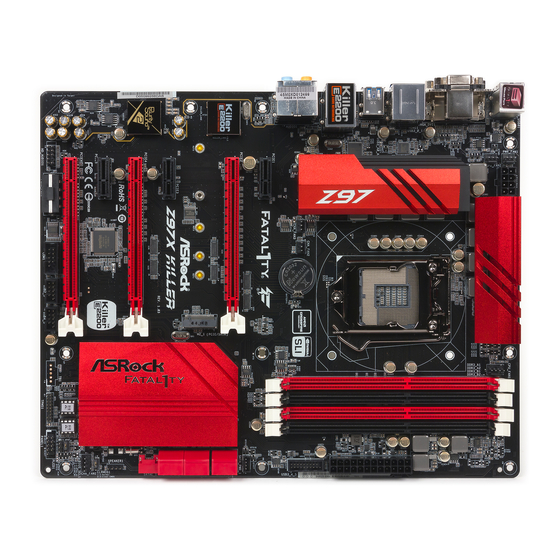
Seite 5: Motherboard-Layout
Fatal1ty Z97 Killer Series Motherboard Layout ATX12V1 PWR_FAN1 CPU_FAN2 CPU_FAN1 USB 3.0 Top: T: USB2 RJ-45 B: USB3 CHA_FAN3 CHA_FAN2 Killer E2200 GAME NETWORKING FATAL TPMS1 PCIE1 Z97 KILLER PCIE2 Purity Sound 2 NUT6 NUT5 NUT4 NUT3 NUT2 Intel CLRMOS1 CMOS PCIE3 64Mb... - Seite 6 No. Description ATX 12V Power Connector (ATX12V1) Power Fan Connector (PWR_FAN1) CPU Fan Connector (CPU_FAN2) CPU Fan Connector (CPU_FAN1) 2 x 240-pin DDR3 DIMM Slots (DDR3_A1, DDR3_B1) 2 x 240-pin DDR3 DIMM Slots (DDR3_A2, DDR3_B2) ATX Power Connector (ATXPWR1) USB 3.0 Header (USB3_4_5) SATA3 Connector (SATA3_1) SATA3 Connector (SATA3_2) SATA3 and SATA Express Connectors (SATAE_5_4)
- Seite 7 Fatal1ty Z97 Killer Series I/O Panel No. Description No. Description USB 2.0 Ports (USB01) Front Speaker (Lime)** D-Sub Port Microphone (Pink) Fatal1ty Mouse Port (USB2) Optical SPDIF Out Port USB 2.0 Port (USB3) USB 3.0 Ports (USB3_2_3) LAN RJ-45 Port* USB 3.0 Ports (USB3_0_1) Central / Bass (Orange) HDMI Port...
- Seite 8 * There are two LEDs on each LAN port. Please refer to the table below for the LAN port LED indications. ACT/LINK LED SPEED LED LAN Port Activity / Link LED Speed LED Status Description Status Description No Link 10Mbps connection Blinking Data Activity Orange...
-
Seite 9: Chapter 1 Introduction
If you require technical support related to this motherboard, please visit our website for specific information about the model you are using. You may find the latest VGA cards and CPU support list on ASRock’s website as well. ASRock website http://www.asrock.com. -
Seite 10: Specifications
Generation Intel® Core Processors (Socket 1150) • Digi Power design • 8 Power Phase design • Supports Intel® Turbo Boost 2.0 Technology • Supports Intel® K-Series unlocked CPUs • Supports ASRock BCLK Full-range Overclocking Downloaded from www.Manualslib.com manuals search engine... - Seite 11 Fatal1ty Z97 Killer Series Chipset • Intel® Z97 Memory • Dual Channel DDR3 Memory Technology • 4 x DDR3 DIMM Slots • Supports DDR3 3000+(OC)/2933(OC)/2800(OC)/2400(OC)/ 2133(OC)/ 1866(OC)/1600/1333/1066 non-ECC, un-buffered memory • Max. capacity of system memory: 32GB (see CAUTION) • Supports Intel® Extreme Memory Profile (XMP) 1.3 / 1.2 Expansion • 1 x PCI Express 3.0 x16 Slot (PCIE2: x16 mode) Slot...
- Seite 12 • 1 x DVI-D Port • 1 x HDMI Port • 1 x Optical SPDIF Out Port • 3 x USB 2.0 Ports (Supports ESD Protection (ASRock Full Spike Protection)) • 1 x Fatal1ty Mouse Port (USB 2.0) (Supports ESD Protection (ASRock Full Spike Protection)) • 4 x USB 3.0 Ports (Supports ESD Protection (ASRock Full...
- Seite 13 • 1 x Thunderbolt AIC Connector • 2 x USB 2.0 Headers (Support 4 USB 2.0 ports) (Supports ESD Protection (ASRock Full Spike Protection)) • 1 x USB 3.0 Header (Supports 2 USB 3.0 ports) (Supports ESD Protection (ASRock Full Spike Protection)) BIOS • 2 x 64Mb AMI UEFI Legal BIOS with multilingual GUI sup-...
- Seite 14 Due to limitation, the actual memory size may be less than 4GB for the reservation for system usage under Windows® 32-bit operating systems. Windows® 64-bit operat- ing systems do not have such limitations. You can use ASRock XFast RAM to utilize the memory that Windows® cannot use.
-
Seite 15: Unique Features
ASRock Cloud ASRock partners with Kloudian to make your mobile devices connect to your PC seamlessly! ASRock Cloud allows you to get connected with your PC’s files, music, photos, and video clips remotely with tablets anytime, anywhere. - Seite 16 Windows® 8 brings the ultimate boot up experience. The lightning boot up speed makes it hard to access the UEFI setup. ASRock Restart to UEFI allows users to enter the UEFI automatically when turning on the PC. By enabling this function, the PC will enter the UEFI directly after you restart.
- Seite 17 UEFI easily. ASRock Instant Flash ASRock Instant Flash is a BIOS flash utility embedded in Flash ROM. This conve- nient BIOS update tool allows you to update the system BIOS in a few clicks without preparing an additional floppy diskette or other complicated flash utility. Just save the new BIOS file to your USB storage and launch this tool by pressing <F6>...
- Seite 18 S4/S5 state. ASRock Easy RAID Installer ASRock Easy RAID Installer can help you to copy the RAID driver from the support CD to your USB storage device. After copying the RAID driver to your USB storage device, please change “SATA Mode”...
-
Seite 19: Chapter 2 Installation
Fatal1ty Z97 Killer Series Chapter 2 Installation This is an ATX form factor motherboard. Before you install the motherboard, study the configuration of your chassis to ensure that the motherboard fits into it. Pre-installation Precautions Take note of the following precautions before you install motherboard components or change any motherboard settings. -
Seite 20: Installing The Cpu
2.1 Installing the CPU 1. Before you insert the 1150-Pin CPU into the socket, please check if the PnP cap is on the socket, if the CPU surface is unclean, or if there are any bent pins in the socket. Do not force to insert the CPU into the socket if above situation is found. - Seite 21 Fatal1ty Z97 Killer Series Downloaded from www.Manualslib.com manuals search engine...
- Seite 22 Please save and replace the cover if the processor is removed. The cover must be placed if you wish to return the motherboard for after service. Downloaded from www.Manualslib.com manuals search engine...
- Seite 23 Fatal1ty Z97 Killer Series 2.2 Installing the CPU Fan and Heatsink Downloaded from www.Manualslib.com manuals search engine...
- Seite 24 2.3 Installing Memory Modules (DIMM) This motherboard provides four 240-pin DDR3 (Double Data Rate 3) DIMM slots, and supports Dual Channel Memory Technology. 1. For dual channel configuration, you always need to install identical (the same brand, speed, size and chip-type) DDR3 DIMM pairs. 2.
- Seite 25 Fatal1ty Z97 Killer Series Downloaded from www.Manualslib.com manuals search engine...
- Seite 26 2.4 Expansion Slots (PCI and PCI Express Slots) There are 2 PCI slots and 4 PCI Express slots on the motherboard. Before installing an expansion card, please make sure that the power supply is switched off or the power cord is unplugged. Please read the documentation of the expansion card and make necessary hardware settings for the card before you start the installation.
- Seite 27 Fatal1ty Z97 Killer Series 2.5 Jumpers Setup The illustration shows how jumpers are setup. When the jumper cap is placed on the pins, the jumper is “Short”. If no jumper cap is placed on the pins, the jumper is “Open”. The illustration shows a 3-pin jumper whose pin1 and pin2 are “Short” when a jumper cap is placed on these 2 pins.
- Seite 28 BIOS Selection Jumper (BIOS_SEL1) Default Backup BIOS (see p.1, No. 23) (Main BIOS) This motherboard has two BIOS onboard, a main BIOS (BIOS_A) and a backup BIOS (BIOS_B), which enhances protection for the safety and stability of your system. Normally, the system works on the main BIOS. However, if the main BIOS is corrupted or damaged, please use a jumper cap to short pin2 and pin3, then the backup BIOS will take over on the next system boot.
- Seite 29 Fatal1ty Z97 Killer Series 2.6 Onboard Headers and Connectors Onboard headers and connectors are NOT jumpers. Do NOT place jumper caps over these headers and connectors. Placing jumper caps over the headers and connectors will cause permanent damage to the motherboard. System Panel Header Connect the power PLED+...
- Seite 30 Power LED Header Please connect the chassis (3-pin PLED1) power LED to this header PLED- PLED+ (see p.1, No. 17) PLED+ to indicate the system’s power status. Serial ATA3 Connectors These six SATA3 (SATA3_0: connectors support SATA see p.1, No. 14) data cables for internal SATA3_0 SATA3_1...
- Seite 31 Fatal1ty Z97 Killer Series USB 3.0 Headers Besides four USB 3.0 Vbus Vbus Vbus IntA_PB_SSRX- (19-pin USB3_4_5) ports on the I/O panel, IntA_PA_SSRX- IntA_PB_SSRX+ IntA_PA_SSRX+ (see p.1, No. 8) there is one header on this IntA_PB_SSTX- IntA_PA_SSTX- IntA_PB_SSTX+ motherboard. Each USB IntA_PA_SSTX+ IntA_PB_D- 3.0 header can support...
- Seite 32 (3-pin PWR_FAN1) FAN_SPEED +12V (see p.1, No. 2) CPU Fan Connectors This motherboard pro- FAN_SPEED_CONTROL FAN_SPEED (4-pin CPU_FAN1) vides a 4-Pin CPU fan +12V (see p.1, No. 4) (Quiet Fan) connector. If you plan to connect a (3-pin CPU_FAN2) 3-Pin CPU fan, please FAN_SPEED (see p.1, No.
- Seite 33 Fatal1ty Z97 Killer Series TPM Header This connector supports (17-pin TPMS1) Trusted Platform Module (see p.1, No. 25) (TPM) system, which can securely store keys, digital certificates, passwords, PCIRST# FRAME and data. A TPM system PCICLK also helps enhance network security, protects digital identities, and ensures platform integrity.
- Seite 34 2.7 M.2_SSD (NGFF) Module Installation Guide The M.2, also known as the Next Generation Form Factor (NGFF), is a small size and versatile card edge connector that aims to replace mPCIe and mSATA. The M.2_SSD (NGFF) Socket 3 can accommodate either a M.2 SATA3 6.0 Gb/s module or a M.2 PCI Express module up to Gen 2 x2 (10 Gb/s).
- Seite 35 Fatal1ty Z97 Killer Series Step 3 Move the standoff based on the module type and length. The standoff is placed at the nut location D by default. Skip Step 3 and 4 and go straight to Step 5 if you are going to use the default nut.
- Seite 36 ADATA AXNS381E-256GM-B SanDisk SD6PP4M-128G Crucial CT120M500SSD4/120G SanDisk SD6PP4M-256G Crucial CT240M500SSD4/240G Samsung XP941-512G (MZHPU512HCGL) Intel SSDSCKGW080A401/80G Kingston RBU-SNS8400S3/180GD For the latest updates of M.2_SSD (NFGG) module support list, please visit our website for details: http://www.asrock.com Downloaded from www.Manualslib.com manuals search engine...
- Seite 37 Fatal1ty Z97 Killer Series 1 Einleitung Vielen Dank für den Kauf unseres ASRock Fatal1ty Z97 Killer Series, eines zuverlässigen Motherboards, das nach ASRocks strengen Qualitätsrichtlinien gefertigt wurde. Es liefert ausgezeichnete Leistung mit robustem Design, das ASRocks Streben nach Qualität und Beständigkeit erfüllt.
-
Seite 38: Technische Daten
-Prozessoren (Sockel 1150) der 4 & Prozessor Generation • Digipower-Design • 8-Leistungsphasendesign • Unterstützt Intel® Turbo Boost 2.0-Technologie • Unterstützt CPUs mit freiem Multiplikator der Intel® K-Serie • Unterstützt ASRock BCLK-Übertaktung (voller Bereich) Chipsatz • Intel® Z97 Downloaded from www.Manualslib.com manuals search engine... - Seite 39 Fatal1ty Z97 Killer Series Speicher • Dualkanal-DDR3-Speichertechnologie • 4 x DDR3-DIMM-Steckplätze • Unterstützt DDR3 3000+(OC)/2933(OC)/2800(OC)/240 0(OC)/2133(OC)/1866(OC)/1600/1333/1066 non-ECC, ungepufferter Speicher • Systemspeicher, max. Kapazität: 32 GB (siehe ACHTUNG) • Unterstützt Intel® Extreme Memory Profile (XMP)1.3/1.2 Erweiter- • 1 x PCI-Express 3.0-x16-Steckplatz (PCIE2:x16-Modus) • 1 x PCI-Express 2.0-x16-Steckplatz (PCIE4:x4-Modus) ungssteck- * Wenn der PCIE1- oder PCIE3-Steckplatz belegt ist, läuft der...
- Seite 40 Audio • 7.1-Kanal-HD-Audio mit Inhaltsschutz (Realtek ALC1150- Audiocodec) • Erstklassige Blu-ray-Audiounterstützung • Unterstützt Überspannungsschutz (ASRock Full Spike Protection) • Unterstützt Purity Sound - Nichicon-Audiokappen der Fine Gold-Serie - 115-dB-SRV-DAC mit Differentialverstärker - TI® NE5532 – erstklassiger Headset-Verstärker (unterstützt Headsets mit bis zu 600 Ohm)
- Seite 41 • 1 x Audioanschluss an Frontblende • 1 x Thunderbolt-Erweiterungskartenanschluss • 2 x USB 2.0-Stiftleisten (unterstützen 4 USB 2.0-Ports) (unterstützt Schutz gegen elektrostatische Entladung (ASRock Full Spike Protection)) • 1 x USB 3.0-Stiftleiste (unterstützt 2 USB 3.0-Ports) (unterstützt Schutz gegen elektrostatische Entladung (ASRock...
- Seite 42 Aufgrund von Beschränkungen kann die Größe des tatsächlich für die Systemnutzung reservierten Speichers unter Windows®-Betriebssystemen mit 32 Bit weniger als 4 GB betragen. Windows®-Betriebssysteme mit 64 Bit haben keine derartigen Beschränkungen. Mit ASRock XFast RAM können Sie den Speicher einsetzen, den Windows® nicht nutzen kann. Downloaded from www.Manualslib.com...
-
Seite 43: Jumpereinstellung
Fatal1ty Z97 Killer Series 1.3 Jumpereinstellung Die Abbildung zeigt, wie die Jumper eingestellt werden. Wenn die Jumper-Kappe auf den Kontakten angebracht ist, ist der Jumper „kurzgeschlossen“. Wenn keine Jumper- Kappe auf den Kontakten angebracht ist, ist der Jumper „offen“. Die Abbildung zeigt einen 3-poligen Jumper, dessen Kontakt 1 und Kontakt 2 „kurzgeschlossen“... - Seite 44 BIOS-Auswahl-Jumper (BIOS_SEL1) Standard Ausfall-BIOS (siehe S. 1, Nr. 23) (Haupt-BIOS) Dieses Motherboard verfügt über zwei integrierte BIOS, ein Haupt-BIOS (BIOS_A) und ein Ausfall-BIOS (BIOS_B), die den Schutz in puncto Sicherheit und Stabilität Ihres Systems steigern. Normalerweise läuft das System über das Haupt-BIOS.
-
Seite 45: Integrierte Stiftleisten Und Anschlüsse
Fatal1ty Z97 Killer Series 1.4 Integrierte Stiftleisten und Anschlüsse Integrierte Stiftleisten und Anschlüsse sind KEINE Jumper. Bringen Sie KEINE Jumper- Kappen an diesen Stiftleisten und Anschlüssen an. Durch Anbringen von Jumper-Kappen an diesen Stiftleisten und Anschlüssen können Sie das Motherboard dauerhaft beschädi- gen. - Seite 46 Betrieb-LED-Stiftleiste Bitte verbinden Sie die (3-polig, PLED1) Betrieb-LED des Gehäuses PLED- PLED+ (siehe S. 1, Nr. 17) zur Anzeige des System- PLED+ betriebsstatus mit dieser Stiftleiste. Serial-ATA-III-Anschlüsse Diese sechs SATA-III- (SATA3_0: Anschlüsse unterstützen siehe S. 1, Nr. 14) SATA-Datenkabel für SATA3_0 SATA3_1 SATA3_2...
- Seite 47 Fatal1ty Z97 Killer Series USB 3.0-Stiftleisten Neben vier USB 3.0-Ports Vbus Vbus (19-polig, USB3_4_5) an der E/A-Blende befindet Vbus IntA_PB_SSRX- IntA_PA_SSRX- IntA_PB_SSRX+ (siehe S. 1, Nr. 8) sich eine Stiftleiste an IntA_PA_SSRX+ IntA_PB_SSTX- diesem Motherboard. Jede IntA_PA_SSTX- IntA_PB_SSTX+ USB 3.0-Stiftleiste kann IntA_PA_SSTX+ IntA_PB_D- zwei Ports unterstützen.
- Seite 48 (3-polig, PWR_FAN1) FAN_SPEED +12V (siehe S. 1, Nr. 2) CPU-Lüfteranschlüsse Dieses Motherboard bietet FAN_SPEED_CONTROL (4-polig, CPU_FAN1) einen 4-poligen CPU- FAN_SPEED +12V (siehe S. 1, Nr. 4) Lüfteranschluss (lautloser Lüfter). Falls Sie einen (3-polig, CPU_FAN2) 3-poligen CPU-Lüfter (siehe S. 1, Nr. 3) anschließen möchten, FAN_SPEED verbinden Sie ihn bitte mit...
- Seite 49 Fatal1ty Z97 Killer Series TPM-Stiftleiste Dieser Anschluss (17-polig, TPMS1) unterstützt das Trusted (siehe S. 1, Nr. 25) Platform Module- (TPM) System, das Schlüssel, digitale Zertifikate, PCIRST# FRAME Kennwörter und Daten PCICLK sicher aufbewahren kann. Ein TPM-System hilft zudem bei der Stärkung der Netzwerksicherheit, schützt digitale Identitäten und gewährleistet die...
-
Seite 50: Contenu De L'emballage
à modification sans préavis. En cas de modifications du présent document, la version mise à jour sera disponible sur le site Internet ASRock sans notifica- tion préalable. Si vous avez besoin d’une assistance technique pour votre carte mère, veuillez visiter notre site Internet pour plus de détails sur le modèle que vous utilisez. -
Seite 51: Spécifications
• Alimentation à 8 phases • Prend en charge la technologie Intel® Turbo Boost 2.0 • Prend en charge les processeurs débloqués de la série K Intel® • Prend en charge l’ o verclocking ASRock BCLK Full-range Chipset • Intel® Z97 Downloaded from www.Manualslib.com... - Seite 52 Mémoire • Technologie mémoire double canal DDR3 • 4 x fentes DIMM DDR3 • Prend en charge les mémoires sans tampon non ECC DDR3 3000+(OC)/2933(OC)/2800(OC)/2400(OC)/2133( OC)/1866(OC)/1600/1333/1066 • Capacité max. de la mémoire système : 32Go (voir AVERTISSEMENT) • Prend en charge Intel® Extreme Memory Profile (XMP)1.3/1.2 Fente • 1 x fente PCI Express 3.0 x 16 (PCIE2 :mode x16)
- Seite 53 • 1 x port sortie optique SPDIF • 3 x ports USB 2.0 (Protection contre les décharges élec- trostatiques (Protection complète contre les pics ASRock)) • 1 x ports souris Fatal1ty (USB 2.0) (Protection contre les décharges électrostatiques (Protection complète contre les pics ASRock)) • 4 x ports USB 3.0 (Protection contre les décharges élec-...
- Seite 54 • 2 x embases USB 2.0 (4 ports USB 2.0 pris en charge) (Protection contre les décharges électrostatiques (Protection complète contre les pics ASRock)) • 1 x embase USB 3.0 (2 ports USB 3.0 pris en charge) (Protection contre les décharges électrostatiques (Protection complète contre les pics ASRock))
- Seite 55 • FCC, CE, WHQL • ErP/EuP Ready (alimentation ErP/EuP ready requise) * pour des informations détaillées de nos produits, veuillez visiter notre site : http://www.asrock.com Il est important de signaler que l'overcloking présente certains risques, incluant des modifi- cations du BIOS, l’ a pplication d’une technologie d’ o verclocking déliée et l'utilisation d'outils d'overclocking développés par des tiers.
- Seite 56 1.3 Configuration des cavaliers (jumpers) L’illustration ci-dessous vous renseigne sur la configuration des cavaliers (jumpers). Lorsque le capuchon du cavalier est installé sur les broches, le cavalier est « court- circuité ». Si le capuchon du cavalier n’ e st pas installé sur les broches, le cavalier est « ouvert ».
- Seite 57 Fatal1ty Z97 Killer Series Sélection du cavalier du BIOS Par défaut BIOS de (BIOS_SEL1) (BIOS principal) secours (voir p.1, No. 23) Cette carte mère est dotée de deux BIOS – un BIOS principal (BIOS_A), et un BIOS de secours (BIOS_B) – ce qui permet d’ o ptimiser la protection du système pour des performances fiables et stables.
- Seite 58 1.4 Embases et connecteurs de la carte mère Les embases et connecteurs situés sur la carte NE SONT PAS des cavaliers. Ne placez JAMAIS de capuchons de cavaliers sur ces embases ou connecteurs. Placer un capuchon de cavalier sur ces embases ou connecteurs endommagera irrémédiablement votre carte mère. Embase du panneau Branchez le bouton de PLED+...
- Seite 59 Fatal1ty Z97 Killer Series Embase LED Veuillez brancher le d’alimentation LED d’alimentation du PLED- PLED+ (PLED1 à 3 broches) châssis sur cette embase PLED+ (voir p.1, No. 17) pour indiquer l’ é tat d’alimentation du système. Connecteurs Serial ATA3 Ces six connecteurs (SATA3_0: SATA3 sont compatibles voir p.1, No.
- Seite 60 Embases USB 3.0 En plus des quatre ports Vbus Vbus (USB3_4_5 à 19 broches) USB 3.0 sur le panneau Vbus IntA_PB_SSRX- IntA_PA_SSRX- IntA_PB_SSRX+ (voir p.1, No. 8) E/S, cette carte mère IntA_PA_SSRX+ IntA_PB_SSTX- est dotée d’une embase IntA_PA_SSTX- IntA_PB_SSTX+ supplémentaire. Chaque IntA_PA_SSTX+ IntA_PB_D- embase USB 3.0 peut...
- Seite 61 Fatal1ty Z97 Killer Series (PWR_FAN1 à 3 broches) FAN_SPEED +12V (voir p.1, No. 2) Connecteurs du Cette carte mère est dotée FAN_SPEED_CONTROL ventilateur du processeur d’un connecteur pour FAN_SPEED +12V (CPU_FAN1 à 4 broches) ventilateur de processeur (voir p.1, No. 4) (Quiet Fan) à...
- Seite 62 Embase TPM Ce connecteur prend en (TPMS1 à 17 broches) charge un module TPM (voir p.1, No. 25) (Trusted Platform Module – Module de plateforme sécurisée), qui permet de PCIRST# FRAME sauvegarder clés, certificats PCICLK numériques, mots de passe et données en toute sécurité.
-
Seite 63: Contenuto Della Confezione
Nel caso di eventuali modifiche del presente manuale, la versione aggiornata sarà disponibile sul sito Web di ASRock senza ulteriore preavviso. Per il supporto tecnico correlato a questa scheda madre, visitare il nostro sito Web per informazioni specifiche relative al modello attualmente in uso. - Seite 64 • MOSFET NexFET • Cappucci di platino 12K (condensatori polimerici conduttivi d’alta qualità prodotti al 100% in Giappone) • PCB Sapphire Black Protezione completa ASRock dai picchi di corrente ASRock Cloud APP Shop ASRock Armatura Potenza CPU • Connettore alimentazione ad alta densità...
- Seite 65 Fatal1ty Z97 Killer Series Memoria • Tecnologia con memoria DDR3 a doppio canale • 4 alloggi DIMM DDR3 • Supporto di memoria DDR3 3000+(OC)/2933(OC)/2800(OC )/2400(OC)/2133(OC)/1866(OC)/1600/1333/1066 non-ECC, un-buffered • Capacità max. della memoria di sistema: 32 GB (si veda la sezione ATTENZIONE) • Supporta Intel®...
- Seite 66 • 1 x porta HDMI • 1 x porta uscita SPDIF ottico • 3 x Porte USB 2.0 (supporto protezione da scariche elettrostat- iche (ESD) (protezione completa ASRock dai picchi di cor- rente)) • 1 x Porta mouse Fatal1ty (USB 2.0) (supporto protezione da...
- Seite 67 • 2 x Collettori USB 2.0 (supporto di 4 porte 4 USB 2.0) (supporto protezione da scariche elettrostatiche (ESD) (protezione completa ASRock dai picchi di corrente)) • 1 x Collettore USB 3.0 (supporta 2 porte USB 3.0) (supporto protezione da scariche elettrostatiche (ESD) (protezione...
- Seite 68 4 GB per riservare l'uso del sistema ai sistemi operativi di Windows® a 32 bit. I sistemi operativi Windows® a 64 bit non possiedono tali limitazioni. È possibile utilizzare la RAM XFast di ASRock per utilizzare la memoria che Windows® non può utilizzare. Downloaded from www.Manualslib.com...
- Seite 69 Fatal1ty Z97 Killer Series 1.3 Impostazione jumper L'illustrazione mostra in che modo vengono impostati i jumper. Quando il cappuccio del jumper è posizionato sui pin, il jumper è "cortocircuitato". Se sui pin non è posizionato alcun cappuccio del jumper, il jumper è "aperto". L'illustrazione mostra un jumper a 3 pin i cui pin1 e pin2 sono "cortocircuitati"...
- Seite 70 Jumper di selezione BIOS (BIOS_SEL1) predefinito BIOS di (vedere pag. 1, n. 23) (Main BIOS) backup Questa scheda madre è dotata di due BIOS, un BIOS principale (BIOS_A) e un BIOS di backup (BIOS_B), che migliorano la protezione, la sicurezza e la stabilità del sistema.
- Seite 71 Fatal1ty Z97 Killer Series 1.4 Header e connettori sulla scheda Gli header e i connettori sulla scheda NON sono jumper. NON posizionare cappucci del jumper su questi header e connettori. Il posizionamento di cappucci del jumper su header e connettori provocherà danni permanenti alla scheda madre. Header sul pannello del Collegare l'interruttore PLED+...
- Seite 72 Header LED di Collegare il LED di alimentazione alimentazione chassis a PLED- PLED+ (PLED1 a 3 pin) questo header per indicare PLED+ (vedere pag. 1, n. 17) lo stato di alimentazione del sistema. Connettori Serial ATA3 Questi sei connettori (SATA3_0: SATA3 supportano cavi vedere pag.1, n.
- Seite 73 Fatal1ty Z97 Killer Series Header USB 3.0 Oltre alle quattro porte Vbus Vbus Vbus IntA_PB_SSRX- (USB3_4_5 a 19 pin) USB 3.0 sul pannello I/O, IntA_PA_SSRX- IntA_PB_SSRX+ (vedere pag. 1, n. 8) su questa scheda madre IntA_PA_SSRX+ IntA_PB_SSTX- vi è un header. Ciascun IntA_PA_SSTX- IntA_PB_SSTX+ IntA_PA_SSTX+...
- Seite 74 (PWR_FAN1 a 3 pin) FAN_SPEED +12V (vedere pag. 1, n. 2) Connettori della ventola Questa scheda madre è FAN_SPEED_CONTROL della CPU FAN_SPEED dotata di un connettore per +12V (CPU_FAN1 a 4 pin) la ventola della CPU (Ven- (vedere pag. 1, n. 4) tola silenziosa) a 4 pin.
- Seite 75 Fatal1ty Z97 Killer Series Header TPM Questo connettore (TPMS1 a 17 pin) supporta il sistema Trusted (vedere pag. 1, n. 25) Platform Module (TPM), che può archiviare in modo sicuro chiavi, certificati PCIRST# FRAME digitali, password e dati. PCICLK Un sistema TPM permette anche di potenziare la sicurezza della rete, di proteggere identità...
-
Seite 76: Contenido Del Paquete
1 Introducción Gracias por adquirir la placa base de la serie ASRock Fatal1ty Z97 Killer, una placa base fiable fabricada siguiendo el sistemáticamente estricto control de calidad de ASRock. Ofrece un rendimiento excelente con un diseño resistente de acuerdo con el compromiso de calidad y resistencia de ASRock. -
Seite 77: Especificaciones
• NexFET MOSFET • Tapas de platino de 12K (condensadores de polímero conductor de alta calidad, 100% fabricados en Japón) • PCB de zafiro negro Protección ASRock Full Spike ASRock Cloud Tienda de aplicaciones ASRock Caracterís- Alimentación de CPU • Conector de alimentación de alta densidad... - Seite 78 Memoria • Tecnología de memoria de Doble Canal DDR3 • 4 ranuras DDR3 DIMM • Compatible con memoria no-ECC, sin búfer DDR3 3000+(OC)/2933(OC)/2800(OC)/2400(OC)/2133(OC)/1866( OC)/1600/1333/1066 • Capacidad máxima de la memoria del sistema: 32GB (consulte la ADVERTENCIA) • Compatible con Extreme Memory Profile (XMP)1.3/1.2 de Intel®...
- Seite 79 • 3 puertos USB 2.0 (compatible con protección contra electrici- dad estática (protección ASRock Full Spike)) • 1 puerto de ratón Fatal1ty (USB 2.0) (compatible con protec- ción contra electricidad estática (protección ASRock Full Spike)) • 4 puertos USB 3.0 (compatible con protección contra electrici- dad estática (protección ASRock Full Spike))
- Seite 80 • 1 conector Thunderbolt AIC • 2 cabezales USB 2.0 (compatible con 4 puertos USB 2.0) (compatible con protección contra electricidad estática (protección ASRock Full Spike)) • 1 cabezal USB 3.0 (compatible con 2 puertos USB 3.0) (compatible con protección contra electricidad estática (protección ASRock Full Spike))
- Seite 81 Windows® de 32 bits. Los sitemas operativos Windows® de 64 bits no tienen estas limitaciones. Podrá utilizar XFast RAM de ASRock para usar la memoria que Windows® no puede utilizar. Downloaded from www.Manualslib.com...
- Seite 82 1.3 Instalación de los puentes La instalación muestra cómo deben instalarse los puentes. Cuando la tapa de puente se coloca en los pines, el puente queda “Corto”. Si no coloca la tapa de puente en los pines, el puente queda “Abierto”. La ilustración muestra un puente de 3 pines cuyo pin 1 y pin 2 son “Cortos”...
- Seite 83 Fatal1ty Z97 Killer Series Puente de selección del BIOS BIOS de copia (BIOS_SEL1) Predeterminado de seguridad (BIOS Principal) (consulte la pág.1, N.º 23) Esta placa base contiene dos BIOS integrados, un BIOS principal (BIOS_A) y un BIOS de copia de seguridad (BIOS_B), que aumentan la protección para la seguridad y la estabilidad de su sistema.
- Seite 84 1.4 Conectores y cabezales incorporados Los cabezales y conectores incorporados NO son puentes. NO coloque tapas de puente so- bre estos cabezales y conectores. Si coloca tapas de puente sobre los cabezales y conectores dañará de forma permanente la placa base. Cabezal del panel del Conecte el interruptor de PLED+...
- Seite 85 Fatal1ty Z97 Killer Series Cabezal de indicador LED Conecte el indicador LED de alimentación de alimentación del chasis PLED- PLED+ (PLED1 de 3 pines) a este cabezal para indicar PLED+ (consulte la pág.1, N.º 17) el estado de alimentación del sistema. Conectores Serie ATA3 Estos seis conectores (SATA3_0:...
- Seite 86 Cabezales USB 3.0 Además de cuatro puertos Vbus Vbus (USB3_4_5 de 19 pines) USB 3.0 en el panel I/O, Vbus IntA_PB_SSRX- IntA_PA_SSRX- IntA_PB_SSRX+ (consulte la pág.1, N.º 8) esta placa base contiene un IntA_PA_SSRX+ IntA_PB_SSTX- cabezal. Cada cabezal USB IntA_PA_SSTX- IntA_PB_SSTX+ 3.0 admite dos puertos.
- Seite 87 Fatal1ty Z97 Killer Series (PWR_FAN1 de 3 pines) FAN_SPEED +12V (consulte la pág.1, N.º 2) Conectores del ventilador Esta placa base contiene FAN_SPEED_CONTROL de la CPU un conector de ventilador FAN_SPEED +12V (CPU_FAN1 de 4 pines) (ventilador silencioso) de (consulte la pág.1, N.º 4) CPU de 4 pines.
- Seite 88 Cabezal TPM Este conector es (TPMS1 de 17 pines) compatible con el sistema (consulte la pág.1, N.º 25) Módulo de Plataforma Segura (TPM, en inglés), que puede almacenar PCIRST# FRAME de forma segura claves, PCICLK certificados digitales, contraseñas y datos. Un sistema TPM también ayuda a aumentar la seguridad en la red, protege...
-
Seite 89: Комплект Поставки
1.1 Комплект поставки • Системная плата ASRock Fatal1ty Z97 Killer (форм-фактор ATX) • Краткое руководство по установке платы ASRock Fatal1ty Z97 Killer • Компакт-диск с ПО для платы Fatal1ty Z97 Killer • 4 х кабеля передачи данных Serial ATA (SATA) (приобретаются отдельно) • 1 х... - Seite 90 • Конденсаторы 12K Platinum (с использованием высококачественных конденсаторов из проводящих полимеров производства Японии) • Печатная плата Sapphire Black Технология полной защиты от импульсных пиков напряжения ASRock Full Spike Protection ASRock Cloud Веб-магазин ASRock APP Shop Питание ЦП Игровое оборудование • Высокоплотный разъем питания...
- Seite 91 Fatal1ty Z97 Killer Series Чипсет • Intel® Z97 Память • Двухканальная память DDR3 • 4 гнезда DDR3 DIMM • Поддержка модулей памяти DDR3 3000+(OC)/2933(OC)/2800(OC)/2400(OC) /2133(OC)/1866(OC)/1600/1333/1066 Non- ECC Unbuffered • Максимальный объем системной памяти: 32 Гб (см. «ПРЕДОСТЕРЕЖЕНИЕ») • Поддержка Intel® Extreme Memory Profile (XMP)1.3/1.2 Слот...
- Seite 92 Аудио • 7.1-канальный звук высокой четкости HD Audio с защитой данных (аудиокодек Realtek ALC1150) • Поддержка Premium Blu-ray Audio • Защита от перенапряжения (ASRock Full Spike Protection) • Поддержка Purity Sound - Конденсаторы для аудиосистем серии Nichicon Fine Gold - 115 дБ SNR DAC с дифференциальным...
- Seite 93 • 1 x AIC-разъем Thunderbolt • 2 x Колодки USB 2.0 (до 4 портов USB 2.0) с защитой от электростатического напряжения (ASRock Full Spike Protection) • 1 x Колодка USB 3.0 (до 2 портов USB 3.0) с защитой от электростатического...
- Seite 94 В связи с ограничением при работе под 32-разрядной ОС Windows® фактический объем памяти может быть меньше 4 Гбайт. Для 64-разрядных ОС Windows® таких ограничений нет. Для использования той памяти, которую ОС Windows® не может использовать, используйте ASRock XFast RAM. Downloaded from www.Manualslib.com...
- Seite 95 Fatal1ty Z97 Killer Series 1.3 Установка перемычек Установка перемычек показана на рисунке. При установке колпачковой перемычки на контакты перемычка «замкнута». Если колпачковая перемычка на контакты не установлена, перемычка «разомкнута». На рисунке показана 3-контактная перемычка с замкнутыми контактами 1 и 2 при установке на них колпачковой...
- Seite 96 Перемычка выбора BIOS (BIOS_SEL1) по умолчанию Резервная (См. стр. 1, № 23) (основная BIOS BIOS) Эта материнская плата снабжена двумя BIOS — основной BIOS (BIOS_A) и BIOS резервного копирования (BIOS_B), — что повышает уровень защиты и стабильности работы системы. Обычно система использует основную BIOS.
- Seite 97 Fatal1ty Z97 Killer Series 1.4 Колодки и разъемы, расположенные на материнской плате Расположенные на материнской плате колодки и разъемы перемычками НЕ являются. НЕ устанавливайте на эти колодки и разъемы колпачковые перемычки. Установка колпачковых перемычек на эти колодки и разъемы может вызвать...
- Seite 98 Колодка светодиодного Подключите индикатора питания светодиодный индикатор (3-контактная, PLED1) питания корпуса к PLED- PLED+ (См. стр. 1, № 17) этой колодке, чтобы PLED+ обеспечить индикацию состояния питания системы. Разъемы Serial ATA3 Эти шесть (SATA3_0: разъемов SATA3 см. стр.1, № 14) SATA3_0 SATA3_1 SATA3_2...
- Seite 99 Fatal1ty Z97 Killer Series Колодки USB 3.0. Кроме четырех портов Vbus Vbus (19-контактная, USB 3.0 на панели ввода- Vbus IntA_PB_SSRX- USB3_4_5) IntA_PB_SSRX+ вывода на материнской IntA_PA_SSRX- IntA_PA_SSRX+ (См. стр. 1, № 8) плате также есть IntA_PB_SSTX- IntA_PA_SSTX- IntA_PB_SSTX+ одна колодка. Каждая IntA_PA_SSTX+ колодка...
- Seite 100 (3-контактный, FAN_SPEED PWR_FAN1) +12V (См. стр. 1, № 2) Разъемы вентиляторов Эта материнская FAN_SPEED_CONTROL ЦП плата снабжена FAN_SPEED +12V (4-контактный, 4-контактным разъемом CPU_FAN1) для малошумящего (См. стр. 1, № 4) вентилятора ЦП. Если вы собираетесь подключить (3-контактный, 3-контактный FAN_SPEED CPU_FAN2) FAN_VOLTAGE вентилятор...
- Seite 101 Fatal1ty Z97 Killer Series Колодка ТРМ Этот разъем (17-контактная, TPMS1) обеспечивает поддержку (См. стр. 1, № 25) системы Trusted Platform Module (TPM), которая способна обеспечить PCIRST# FRAME надежное хранение PCICLK ключей, цифровых сертификатов, паролей и данных. Система ТРМ также повышает уровень сетевой...
-
Seite 102: Conteúdo Da Embalagem
No caso de ocorrerem modificações neste manual, a versão atualizada estará disponível no site da ASRock sem aviso prévio. Se precisar de assistência técnica relacionada a esta placa principal, visite o nosso site para obter informações específicas sobre o modelo que estiver utilizando. - Seite 103 • Design Digi Power • Design com 8 fases de alimentação • Suporta a tecnologia Intel® Turbo Boost 2.0 • Suporta CPU desbloqueado da série K da Intel® • Suporta Overclocking total ASRock BCLK Chipset • Intel® Z97 Downloaded from www.Manualslib.com...
- Seite 104 Memória • Tecnologia de memória DDR3 de dois canais • 4 x Slots DIMM DDR3 • Suporta DDR3 3000+(OC)/2933(OC)/2800(OC)/2400(OC) /2133(OC)/ 1866(OC)/1600/1333/1066 não-ECC, memória tampão sem armazenamento • Capacidade máxima da memória do sistema: 32GB (ver CUIDADO) • Suporta Extreme Memory Profile (XMP)1.3/1.2 da Intel® Slot de • 1 x Slot PCI Express 3.0 x16 (PCIE2:modo x16) • 1 x Slot PCI Express 2.0 x16 (PCIE4:modo x4)
- Seite 105 • 3 Portas USB 2.0 (Suporta Proteção ESD (Proteção Total Con- tra Picos ASRock)) • 1 x Porta para rato Fatal1ty (USB 2.0) (Suporta Proteção ESD (Proteção Total Contra Picos ASRock)) • 4 Portas USB 3.0 (Suporta Proteção ESD (Proteção Total Con- tra Picos ASRock)) • 1 x Porta LAN RJ-45 com LED (LED ACT/LINK e LED DE...
- Seite 106 • 1 x Conector Thunderbolt AIC • 2 x Plataformas USB 2.0 (Suporta 4 portas USB 2.0) (Suporta Proteção ESD (Proteção Total Contra Picos ASRock)) • 1 x Plataforma USB 3.0 (Suporta 2 portas USB 3.0) (Suporta Proteção ESD (Proteção Total Contra Picos ASRock)) Funções...
- Seite 107 * Para obter informações detalhadas sobre o produto, por favor, visite o nosso site: http://www.asrock.com Por favor, observe que existe um certo risco envolvendo overclocking, incluindo o ajuste das definições na BIOS, a aplicação de tecnologia Untied Overclocking ou a utilização de ferramentas de overclocking de terceiros.
- Seite 108 1.3 Configuração dos jumpers A imagem abaixo mostra como os jumpers são configurados. Quando a tampa do jumper é colocada nos pinos, o jumper é "Curto". Se não for colocada uma tampa de jumper nos pinos, o jumper é "Aberto". A imagem mostra um jumper de 3 pinos cujos pino1 e pino2 estão "Curtos"...
- Seite 109 Fatal1ty Z97 Killer Series Jumper de seleção da BIOS (BIOS_SEL1) Padrão Fazer o (ver p.1, N.º 23) (BIOS principal) backup de BIOS Esta placa-mãe possui duas BIOS integradas, uma BIOS principal (BIOS_A) e uma BIOS de reserva (BIOS_B), que aumenta a proteção, segurança e estabilidade do seu sistema.
- Seite 110 1.4 Suportes e conectores onboard Os conectores e suportes onboard NÃO são jumpers. NÃO coloque tampas de jumpers sobre estes terminais e conectores. Colocar tampas de jumpers sobre os terminais e conectores irá causar danos permanentes à placa-mãe. Suporte do painel de Ligue o botão de PLED+ PLED-...
- Seite 111 Fatal1ty Z97 Killer Series Suporte LED de Por favor, conecte o LED alimentação de alimentação do chassi PLED- PLED+ (PLED1 de 3 pinos) neste suporte para indicar PLED+ (ver p.1, N.º 17) o estado de alimentação do sistema. Conectores série ATA3 Estes seis conectores (SATA3_0: SATA3 suportam...
- Seite 112 Suportes USB 3.0 Além das quatro portas Vbus Vbus (USB3_4_5 de 19 pinos) USB 3.0 no painel de E/ Vbus IntA_PB_SSRX- IntA_PA_SSRX- IntA_PB_SSRX+ (ver p.1, N.º 8) S, existe um suporte nesta IntA_PA_SSRX+ IntA_PB_SSTX- placa principal. Cada IntA_PA_SSTX- IntA_PB_SSTX+ suporte USB 3.0 pode IntA_PA_SSTX+ IntA_PB_D- suportar duas portas.
- Seite 113 Fatal1ty Z97 Killer Series (PWR_FAN1 de 3 pinos) FAN_SPEED +12V (ver p.1, N.º 2) Conectores do ventilador Esta placa mãe inclui um FAN_SPEED_CONTROL da CPU conector de ventilador FAN_SPEED +12V (CPU_FAN1 de 4 pinos) da CPU (Ventilador (ver p.1, N.º 4) silencioso) de 4 pinos.
- Seite 114 Suporte TPM Este conector suporta (TPMS1 de 17 pinos) um sistema com Módulo (ver p.1, N.º 25) de Plataforma Confiável (TPM), que pode armazenar com segurança PCIRST# FRAME chaves, certificados PCICLK digitais, senhas e dados. Um sistema TPM também ajuda a melhorar a segurança de rede, a proteger identidades digitais e a garantir a...
-
Seite 115: Ambalaj İçeriği
1 Giriş Zorlu kalite kontrol süreçlerinden geçmiş olan ASRock Fatal1ty Z97 Killer Serisi anakartını satın aldığınız için teşekkür ederiz. Sağlam tasarımı ile ASRock'ın kalite ve dayanıklılık taahhüdüne uygun şekilde mükemmel performans sağlar. Anakart özellikleri ve BIOS yazılımı güncellenebileceğinden, bu kılavuzun içeriği herhangi bir bildirimde bulunulmaksızın değiştirilebilir. - Seite 116 • Dijital Güç tasarımı • 8 Güç Safhası tasarımı • Intel® Turbo Boost 2.0 Teknolojisini destekler • Intel® K Serisi kilitsiz işlemcileri destekler • ASRock BCLK tam aralıklı Hız Aşırtmayı destekler Yonga kümesi • Intel® Z97 Downloaded from www.Manualslib.com...
- Seite 117 Fatal1ty Z97 Killer Series Bellek • Çift Kanallı DDR3 Bellek Teknolojisi • 4 x DDR3 DIMM Yuvası • ECC olmayan, ara belleğe alınmamış DDR3 3000+(OC )/2933(OC)/2800(OC)/2400(OC)/2133(OC)/1866( OC)/1600/1333/1066 belleği destekler • Maksimum sistem belleği kapasitesi: 32GB (bkz. DİKKAT) • Intel® Üstün Bellek Profili (XMP)1.3/1.2 özelliğini destekler Genişletme • 1 x PCI Express 3.0 x16 Yuva (PCIE2:x16 modu)
- Seite 118 • İçerik Koruma Özelliği ile 7.1 CH HD Ses (Realtek ALC1150 Ses Codec Bileşeni) • Üstün Blu-ray Ses desteği • Dalgalanma Koruması Destekler (ASRock Tam Ani Gerilim Koruması) • Purity Sound 2 destekler - Nichicon Fine Gold Serisi Ses Kapakları...
- Seite 119 • 1 x Ön Panel Ses Bağlayıcısı • 1 x Thunderbolt AIC Bağlayıcısı • 2 x USB 2.0 Bağlantısı (4 USB 2.0 bağlantı noktası destekler) (ESD Koruması Destekler (ASRock Tam Ani Gerilim Koruması)) • 1 x USB 3.0 Bağlantısı (2 USB 3.0 bağlantı noktası...
- Seite 120 • ErP/EuP için hazır (ErP/EuP için hazır güç beslemesi gereklidir) * Detaylı ürün bilgisi için, lütfen web sitemizi ziyaret edin: http://www.asrock.com Lütfen, BIOS ayarlarını düzenleme, Bağımsız Hız Aşırtma Teknolojinin uygulanması ya da üçüncü kişilerin hız aşırtma araçlarının kullanılması da dahil olmak üzere tüm hız aşırtma işlemlerinin belirli bir risk taşıdığını...
- Seite 121 Fatal1ty Z97 Killer Series 1.3 Bağlantı Teli Kurulumu Çizim, bağlantı tellerinin kurulumunu göstermektedir. Tel kapağı, pimlerin üzerine yerleştirildiğinde, tel "Kısa" olur. Pimlerin üzerinde tel kapağı bulunmadığında, tel "Kısa" olur. Çizim, pin1 ve pin2 alanları "Kısa" olan ve bu iki pim üzerinde bir bağlantı teli kapağı...
- Seite 122 BIOS Seçme Bağlama Teli (BIOS_SEL1) Varsayılan Yedek BIOS (bkz. sf.1, No. 23) (Ana BIOS) Bu anakartta sisteminizin güvenliği ve kararlılığı için korumayı artıran ana BIOS (BIOS_A) ve yedek BIOS (BIOS_B) olmak üzere iki adet BIOS vardır. Normalde sistem ana BIOS'ta çalışır. Ancak ana BIOS bozulur veya hasar görürse, lütfen pin2 ve pin3'ü...
- Seite 123 Fatal1ty Z97 Killer Series 1.4 Ekli Bağlantılar ve Bağlayıcılar Ekli bağlantılar ve bağlayıcılar bağlantı teli değildir. Bağlantı teli kapaklarını bu bağlantı ve bağlayıcılar üzerine yerleştirmeyin. Bağlantı teli kapaklarının bağlantılar ile bağlayıcılar üzerine yerleştirilmesi, anakarta kalıcı hasar verebilir. Sistem Paneli Bağlantısı Güç...
- Seite 124 Güç LED Bağlantısı Sistemin güç durumunun (3-pin PLED1) belirtilmesi için lütfen PLED- PLED+ (bkz. sf.1, No. 17) güç LED'ini bu bağlantıya PLED+ takın. Seri ATA3 Bağlayıcıları Bu altı SATA3 bağlayıcısı, (SATA3_0: veri aktarım hızı 6,0 Gb/ bkz. sf.1, No. 14) sn'ye kadar olan dahili SATA3_0 SATA3_1...
- Seite 125 Fatal1ty Z97 Killer Series USB 3.0 Bağlantıları Bu anakart üzerinde, I/O Vbus Vbus Vbus IntA_PB_SSRX- (19-pin USB3_4_5) paneli üzerindeki dört USB IntA_PA_SSRX- IntA_PB_SSRX+ (bkz. sf.1, No. 8) 3.0 bağlantı noktasının IntA_PA_SSRX+ IntA_PB_SSTX- yanı sıra, bir adet bağlantı IntA_PA_SSTX- IntA_PB_SSTX+ IntA_PA_SSTX+ bulunmaktadır.
- Seite 126 (3-pin PWR_FAN1) FAN_SPEED +12V (bkz sf.1, No. 2) CPU Fan Bağlayıcıları Bu anakart, 4-Pin CPU FAN_SPEED_CONTROL (4-pin CPU_FAN1) FAN_SPEED fan (Sessiz Fan) bağlayıcısı +12V (bkz sf.1, No. 4) sağlamaktadır. 3-Pin CPU fan bağlamak istiyorsanız, (3-pin CPU_FAN2) lütfen Pin 1-3'ü kullanın. (bkz sf.1, No.
- Seite 127 Fatal1ty Z97 Killer Series TPM bağlantısı Bu bağlayıcı, anahtarlar, (17-pin TPMS1) dijital sertifikalar, parolalar (bkz. sf.1, No. 25) ve verileri güvenli bir şekilde saklama özelliği bulunan Güvenilir PCIRST# FRAME Platform Modülü (TPM) PCICLK sistemini destekler. TPM sistemleri, aynı zamanda ağ güvenliğinin artırılması, dijital kimliklerin korunması...
- Seite 128 1 개요 ASRock Fatal1ty Z97 Killer 시리즈 마더보드를 구입해 주셔서 감사합니다 . 이 마 더보드는 ASRock 의 일관되고 엄격한 품질관리 하에 생산되어 신뢰성이 우수합 니다 . 품질과 내구성에 대한 ASRock 의 기준에 부합하는 우수한 성능과 견고한 설계를 제공합니다 . 마더보드 규격과 BIOS 소프트웨어를 업데이트할 수도 있기 때문에 , 이 설명서의...
- Seite 129 프로세서 지원 ( 소켓 1150) • Digi 전원 구조 • 8 개 전원 위상 구조 • Intel® Turbo Boost 2.0 기술 지원 • Intel®K- 시리즈 잠금 해제 CPU 지원 • ASRock BCLK 전범위 오버클로킹 지원 • Intel® Z97 칩세트 Downloaded from www.Manualslib.com...
- Seite 130 • 듀얼 채널 DDR3 메모리 기술 메모리 • DDR3 DIMM 슬롯 4 개 • DDR3 지원 3000+(OC)/2933(OC)/2800(OC)/2400(OC)/213 3(OC)/1866(OC)/1600/1333/1066 비 -ECC, 언버퍼드 메모 리 • 시스템 메모리 최대 용량 : 32GB ( 주의 참조 ) • Intel® Extreme Memory Profile (XMP)1.3/1.2 지원 •...
- Seite 131 • DVI-D 포트 1 개 • HDMI 포트 1 개 • 광학 SPDIF 출력 포트 1 개 • USB 2.0 포트 3 개 (ESD 보호 지원 (ASRock 풀 스파이크 보 호 )) • Fatal1ty 마우스 포트 1 개 (USB 2.0)(ESD 보호 지원 (ASRock 풀...
- Seite 132 • Thunderbolt AIC 커넥터 1 개 • USB 2.0 헤더 2 개 (USB 2.0 포트 4 개 지원 )(ESD 보호 지원 (ASRock 풀 스파이크 보호 )) • USB 3.0 헤더 1 개 (USB 3.0 포트 2 개 지원 )(ESD 보호 지원...
- Seite 133 제한 때문에 실제 메모리 크기는 Windows® 32 비트 운영체제 하의 시스템 사용 을 위한 예비 메모리용 4GB 보다 더 적을 수 있습니다 . Windows® 64 비트 운영체 제에는 그러한 제한이 없습니다 . ASRock XFast RAM 을 사용하여 Windows® 가 사용할 수 없는 메모리를 이용할 수 있습니다 .
- Seite 134 1.3 점퍼 설정 그림은 점퍼를 어떻게 설정하는지 보여줍니다 . 점퍼 캡을 핀에 씌우면 점퍼가 “단락”됩니다 . 점퍼 캡을 핀에 씌우지 않으면 점퍼가 “단선”됩니다 . 그림 은 3 핀 점퍼를 보여주며 핀 1 과 핀 2 는 점퍼 캡을 씌울 때 “단락”됩니다 . Clear CMOS 점퍼...
- Seite 135 Fatal1ty Z97 Killer Series BIOS 선택 점퍼 (BIOS_SEL1) 백업 BIOS 기본값 (1 페이지 , 23 번 항목 참조 ) ( 메인 BIOS) 이 마더보드는 두 개의 BIOS, 즉 메인 BIOS (BIOS_A) 와 백업 BIOS (BIOS_B) 를 탑재하여 시스템의 안전 및 안정성에 대한 보호를 더욱 강화했습니다 . 평소 에...
- Seite 136 1.4 온보드 헤더 및 커넥터 온보드 헤더와 커넥터는 점퍼가 아닙니다 . 점퍼 캡을 온보드 헤더와 커넥터에 씌 우지 마십시오 . 점퍼 캡을 온보드 헤더와 커넥터에 씌우면 마더보드가 영구적으 로 손상됩니다 . 섀시의 전원 스위치 , 시스템 패널 헤더 PLED+ PLED- (9 핀...
- Seite 137 Fatal1ty Z97 Killer Series 전원 LED 헤더 시스템 전원 상태를 나 (3 핀 PLED1) 타내려면 섀시 전원 PLED- PLED+ (1 페이지 , 17 번 항목 참조 ) LED 를 이 헤더에 연 PLED+ 결하십시오 . 시리얼 ATA3 커넥터 이들 6 개의 SATA3 커 (SATA3_0: 넥터는...
- Seite 138 USB 3.0 헤더 I/O 패널에 USB 3.0 포 Vbus Vbus Vbus IntA_PB_SSRX- (19 핀 USB3_4_5) 트 네 개가 탑재되어 IntA_PA_SSRX- IntA_PB_SSRX+ (1 페이지 , 8 번 항목 참조 ) IntA_PA_SSRX+ 있을 뿐 아니라 마더 IntA_PB_SSTX- IntA_PA_SSTX- IntA_PB_SSTX+ 보드에 헤더 한 개가 IntA_PA_SSTX+ 탑재되어...
- Seite 139 Fatal1ty Z97 Killer Series (3 핀 PWR_FAN1) FAN_SPEED +12V (1 페이지 , 2 번 항목 참조 ) CPU 팬 커넥터 이 마더보드에는 4 핀 FAN_SPEED_CONTROL FAN_SPEED (4 핀 CPU_FAN1) CPU 팬 ( 저소음 팬 ) +12V (1 페이지 , 4 번 항목 참조 ) 커넥터가...
- Seite 140 TPM 헤더 이 커넥터는 키 , 디 (17 핀 TPMS1) 지털 인증서 , 암호 (1 페이지 , 25 번 항목 참조 ) 및 데이터를 안전하 게 보관할 수 있는 TPM(Trusted Platform PCIRST# FRAME Module) 시스템을 지원 PCICLK 합니다 . TPM 시스템 은...
- Seite 141 さい。 アスロックのウェブサイ トでは、 最新の VGA カードおよび CPU サポート一覧 もご覧になれます。 アスロックウェブサイ ト http://www.asrock.com. 1.1 パッケージの内容 • ASRock Fatal1ty Z97 Killer シリーズマザーボード (ATX フォームファクタ) • ASRock Fatal1ty Z97 Killer シリーズクイックインストールガイ ド • ASRock Fatal1ty Z97 Killer シリーズサポート CD • 4 x シリアル ATA (SATA) データケーブル (オプション)...
- Seite 142 コア損失を 70% 低減します) • NexFET MOSFET • 12K プラチナコンデンサ (100% 日本製の高品質導電性 ポリマコンデンサ) • サファイアブラック PCB ASRock 完全スパイク保護 ASRock Cloud ASRock APP ショ ップ CPU 電源 ゲーミングの • 高密度電源コネクタ ための武装 メモリ • NexFET MOSFET • DIMM スロッ トに 15 μ ゴールドコンタク トを採用...
- Seite 143 Fatal1ty Z97 Killer Series チップセッ ト • Intel® Z97 • デュアルチャンネル DDR3 メモリテク ノロジー メモリ • 4 x DDR3 DIMM スロッ ト • DDR3 3000+(OC)/2933(OC)/2800(OC)/2400(OC)/2133 (OC)/1866(OC)/1600/1333/1066 ノン ECC、 アンバッフ ァードメモリに対応 • システムメモリの最大容量 : 32GB (注意を参照) • Intel® エクスト リームメモリプロファイル (XMP) 1.3/1.2 をサポート...
- Seite 144 E2200 シリーズ • Qualcomm® Atheros® Killer • クアルコム ® アセロス ® セキュ リティ ウェイクオンインタ ーネッ トテク ノロジーをサポート • ウェイクオンランをサポート • 雷 / 静電気放電 (ESD) 保護に対応 (ASRock 完全スパ イク保護) • エネルギー効率のよいイーサネッ ト 802.3az をサポー ト • PXE をサポート • 1 x PS/2 マウス / キーボードポート...
- Seite 145 • 1 x Thunderbolt AIC コネクタ • 2 x USB 2.0 ヘッダー (4 個の USB 2.0 ポートに対応) ( 静 電気放電 (ESD) 保護に対応 (ASRock 完全スパイク保護) ) • 1 x USB 3.0 ヘッダー (2 個の USB 3.0 ポートに対応) ( 静 電気放電 (ESD) 保護に対応 (ASRock 完全スパイク保護) )...
- Seite 146 64-bit / 7 32-bit / 7 64-bit 認証 • FCC、 CE、 WHQL • ErP/EuP Ready ( ErP/EuP 対応) ( ErP/EuP 対応電源供給 装置が必要です) * 商品詳細については、 当社ウェブサイ トをご覧く ださい。 http://www.asrock.com BIOS 設定の調整、 アンタイ ドオーバークロックテク ノロジーの適用、 サードパーティ のオーバークロックツールの使用などを含む、 オーバークロックには、 一定のリスク を伴いますのでご注意く ださい。 オーバークロックするとシステムが不安定になった り、 システムのコンポーネントやデバイスが破損するこ とがあります。 ご自分の責任...
- Seite 147 Fatal1ty Z97 Killer Series 1.3 ジャンパー設定 このイラストは、 ジャンパーの設定方法を示しています。 ジャンパーキャップがピ ンに被さっていると、 ジャンパーは 「ショート」 です。 ジャンパーキャップがピンに被 さっていない場合には、 ジャンパーは 「オープン」 です。 この図は 3 ピンのジャンパー を表し、 ジャンパーキャップがピン 1 とピン 2 に被さっているとき、 これらのピンは 「ショート」 です。 CMOS ク リアジャンパー (CLRCMOS1) デフォルト CMOS の (p.1、 No. 24 参照) ク...
- Seite 148 BIOS 選択ジャンパー (BIOS_SEL1) デフォルト バックアップ (p.1、 No. 23 参照) (メイン BIOS) BIOS このマザーボードは、 メイン BIOS ( BIOS_A) とバックアップ BIOS ( BIOS_B) の 2 つの BIOS がオンボードにあり、 システムの安全性と安定性のための保護を強化 しています。 通常、 システムはメイン BIOS 上で動作します。 メイン BIOS が壊れた り、 損傷した場合には、 ジャンパーキャップを使用してピン 2 とピン 3 をショート させてく...
- Seite 149 Fatal1ty Z97 Killer Series 1.4 オンボードのヘッダーとコネクター オンボードヘッダーとコネクターはジャンパーではありません。 これらヘッダーとコ ネクターにはジャンパーキャップを被せないでく ださい。 ヘッダーおよびコネクター にジャンパーキャップを被せると、 マザーボードに永久損傷が起こるこ とがあります。 システムパネルヘッダー 電源スイッチを接続し、 PLED+ PLED- (9 ピンパネル 1) スイッチをリセッ トし、 下 PWRBTN# (p.1、 No. 18 参照) 記のピン割り当てに従っ て、 シャーシのシステムス テータス表示ランプをこ RESET# のヘッダーにセッ トしま HDLED- HDLED+ す。 ケーブルを接続すると きには、...
- Seite 150 電源 LED ヘッダー システムの電源ステー (3 ピン PLED1) タスを表示するために、 PLED- PLED+ (p.1、 No. 17 参照) シャーシ電源 LED をこの PLED+ ヘッダーに接続してく だ さい。 シリアル ATA3 コネクタ これら 6 つの SATA3 コネ ー クターは、 最高 6.0 Gb/ 秒 SATA3_0 SATA3_1 SATA3_2 (SATA3_0 : のデータ転送速度で内部...
- Seite 151 Fatal1ty Z97 Killer Series USB 3.0 ヘッダー I/O パネルの 4 つの USB Vbus Vbus (19 ピン USB3_4_5) Vbus IntA_PB_SSRX- 3.0 ポートに加えて、 この IntA_PA_SSRX- IntA_PB_SSRX+ (p.1、 No. 8 参照) マザーボードには 1 つの IntA_PA_SSRX+ IntA_PB_SSTX- ヘッダーがあります。 各 IntA_PA_SSTX- IntA_PB_SSTX+ IntA_PA_SSTX+ USB 3.0 ヘッダーは、 2 つ IntA_PB_D- IntA_PA_D- IntA_PB_D+...
- Seite 152 (3 ピン PWR_FAN1) FAN_SPEED +12V (p.1、 No. 2 参照) CPU ファンコネクター このマザーボードは 4 ピ FAN_SPEED_CONTROL (4 ピン CPU_FAN1) FAN_SPEED ン CPUファン (静音ファン) +12V (p.1、 No. 4 参照) コネクターを提供します。 3 ピンの CPU ファンを接 (3 ピン CPU_FAN2) 続する場合には、 ピン 1-3 (p.1、 No. 3 参照) に接続してく...
- Seite 153 Fatal1ty Z97 Killer Series TPM ヘッダー このコネクターはトラス (17 ピン TPMS1) テッ ドプラッ トフォーム (p.1、 No. 25 参照) モジュール (TPM) システ ムをサポートし、 鍵、 デジ タル証明書、 パスワード、 PCIRST# FRAME データを安全に保管する PCICLK こ とができます。 TPM シ ステムはまた、 ネッ トワー クセキュ リティを高め、 デ ジタル証明書を保護し、 プラッ...
- Seite 154 卓越性能。 由于主板规格和 BIOS 软件可能已更新,因此,本手册的内容可能会随时更改, 恕不另行通知。如果本手册有任何修改,则更新的版本将发布在华擎网站上,我 们不会另外进行通知。如果您需要与此主板相关的技术支持,请访问我们的网站 以具体了解所用型号的信息。您也可以在华擎网站上找到最新 VGA 卡和 CPU 支 持列表。华擎网站 http://www.asrock.com。 1.1 包装清单 • 华擎 Fatal1ty Z97 Killer 系列主板(ATX 规格尺寸) • 华擎 Fatal1ty Z97 Killer 系列主板快速安装指南 • 华擎 Fatal1ty Z97 Killer 系列主板支持光盘 • 4 x 串行 ATA (SATA) 数据线(选购)...
- Seite 155 Fatal1ty Z97 Killer Series 1.2 规格 • ATX 规格尺寸 平台 • 高密度防潮纤维电路板 独有功能 华擎超合金 • 超合金散热器 • 高效合金电感(与铁粉电感相比,内核损耗可降低 70%) • 次世代 MOS • 12K 白金电容(100% 日本生产的优质导电聚合物电容) • 宝石黑 华擎全防护 华擎云 华擎应用市场 电竞盔甲 CPU 电源 • 高密度电源接口 内存 • 次世代 MOS •...
- Seite 156 • 双通道 DDR3 内存技术 内存 • 4 x DDR3 DIMM 槽 • 支持 DDR3 3000+(OC)/2933(OC)/2800(OC)/2400(OC)/2133 (OC)/1866(OC)/1600/1333/1066 非 ECC,非缓冲内存 • 支持系统内存容量: 32GB(见“注意”) • 支持 Intel® Extreme Memory Profile (XMP)1.3/1.2 • 1 x PCI Express 3.0 x16 插槽(PCIE2:x16 模式 ) 扩充槽 • 1 x PCI Express 2.0 x16 插槽(PCIE4:x4 模式 ) * 如果...
- Seite 157 Fatal1ty Z97 Killer Series • 具有内容保护功能的 7.1 CH 高清音频(Realtek ALC1150 音频 音频编解码器) • 优质 Blu-ray 音频支持 • 支持防突波 ( 华擎全防护 ) • 支持高保真 2 代 - Nichicon 专业音效电容 - 115dB SNR DAC 带微分放大器 - TI® NE5532 优质耳放(支持最高 600 Ohm 耳机) - Direct Drive ( 直接驱动...
- Seite 158 • 6 x SATA3 6.0 Gb/s 接口,支持 RAID(RAID 0、RAID 1、 存储 RAID 5、RAID 10、Intel Rapid Storage Technology 13 和 Intel Smart Response Technology)、NCQ、AHCI 和热插拔 • 1 x SATA Express 接口(与 SATAE_4、SATAE_5 和 M.2_ SSD (NGFF) 插座 3 共用) * 即将支持 •...
- Seite 159 • Microsoft® Windows® 8.1 32-bit / 8.1 64-bit / 8 32-bit / 8 64-bit 操作系统 / 7 32-bit / 7 64-bit • FCC、CE、WHQL 认证 • ErP/EuP 支持(需要支持 ErP/EuP 的电源) * 有关详细产品信息,请访问我们的网站: http://www.asrock.com 须认识到超频会有一定风险,包括调整 BIOS 设置,应用“自由超频技术”,或 使用第三方超频工具。超频可能会影响到系统的稳定性,甚至对系统的组件和设 备造成损坏。执行这项工作您应自担风险和自己承担费用。我们对由于超频而造 成的损坏概不负责。 由于限制原因,实际内存容量可能会小于 4GB,以保留给 Windows® 32-bit 操作...
- Seite 160 1.3 跳线设置 此图显示如何设置跳线。将跳线帽装到这些针脚上时,跳线 “短接”。如果这 些针脚上没有装跳线帽,跳线 “开路”。此图显示 3 针跳线,当跳线帽装在针 脚 1 和针脚 2 上,它们“短接”。 清除 CMOS 跳线 (CLRCMOS1) (见第 1 页,第 24 个) 清除 CMOS 默认 CLRCMOS1 允许您清除 CMOS 中的数据。要清除和重置系统参数到默认设 置,请关闭计算机,从电源上拔下电源线插头。等候 15 秒后,使用跳线帽将 CLRCMOS1 上的针脚 2 和针脚 3 短接 5 秒。但是,请勿在更新 BIOS 后立即 清除...
- Seite 161 Fatal1ty Z97 Killer Series BIOS 选择跳线 (BIOS_SEL1) 默认 备份 BIOS (见第 1 页,第 23 个) (主 BIOS) 此主板集成有两个 BIOS,一个是主 BIOS (BIOS_A),一个是备用 BIOS (BIOS_ B),可以增强对于系统安全性和稳定性的保护。通常,系统工作时使用主 BIOS。但是,如果主 BIOS 损坏,请使用跳线帽将针脚 2 和 3 短接,之后备份 BIOS 将执行下一次系统引导。之后,再次短接针脚 1 和 2,然后使用 BIOS 设 置实用程序中的“Secure Backup UEFI”将 BIOS 文件复制到主 BIOS 以确保正 常系统操作。基于系统安全考虑,用户不能手动更新备份...
- Seite 162 1.4 板载接脚和接口 板载接脚和接口不是跳线。不要将跳线帽装到这些接脚和接口上。将跳线帽装到 这些接脚和接口上将会对主板造成永久性损坏。 系统面板接脚 按照下面的针脚分配, PLED+ PLED- (9 针 PANEL1) PWRBTN# 将机箱上的电源开关、 见第 1 页,第 18 个) 重置开关和系统状态指 示灯连接到此接脚。在 RESET# 连接线缆前请记下正负 HDLED- 针脚。 HDLED+ PWRBTN(电源开关): 连接到机箱前面板上的电源开关。您可以配置使用电源开关关闭系统的方式。 RESET(重置开关): 连接到机箱前面板上的重置开关。如果计算机死机,无法执行正常重新启动,按 重置开关重新启动计算机。 PLED(系统电源 LED): 连接到机箱前面板上的电源状态指示灯。系统操作操作时,此 LED 亮起。系统 处在 S1/S3 睡眠状态时,此 LED 闪烁。系统处在 S4 睡眠状态或关机 (S5) 时,此 LED 熄灭。...
- Seite 163 Fatal1ty Z97 Killer Series 电源 LED 接脚 请将机箱电源 LED 连接 (3 针 PLED1) 到此接脚以指示系统电 PLED- PLED+ PLED+ (见第 1 页,第 17 个) 源状态。 串行 ATA3 接口 这六个 SATA3 接口支 (SATA3_0: 持最高 6.0 Gb/s 数据 见第 1 页, SATA3_0 SATA3_1 SATA3_2 传输速率的内部存储...
- Seite 164 USB 3.0 接脚 除 I/O 面板上的四个 USB Vbus Vbus Vbus IntA_PB_SSRX- (19 针 USB3_4_5) 3.0 端口外,此主板上还 IntA_PA_SSRX- IntA_PB_SSRX+ IntA_PA_SSRX+ (见第 1 页,第 8 个) 有一个接脚。每个 USB IntA_PB_SSTX- IntA_PA_SSTX- IntA_PB_SSTX+ 3.0 接脚可以支持两个端 IntA_PA_SSTX+ IntA_PB_D- 口。 IntA_PA_D- IntA_PB_D+ IntA_PA_D+ Dummy 前面板音频接脚 此接脚用于将音频设备 PRESENCE# MIC_RET (9 针...
- Seite 165 Fatal1ty Z97 Killer Series (3 针 PWR_FAN1) FAN_SPEED +12V 见第 1 页,第 2 个) CPU 风扇接口 此主板提供 4 针 CPU 风 FAN_SPEED_CONTROL FAN_SPEED (4 针 CPU_FAN1) 扇(静音风扇)接口。如 +12V 见第 1 页,第 4 个) 果您打算连接 3 针 CPU 风扇,请将它连接到针 (3 针 CPU_FAN2) 脚...
- Seite 166 TPM 接脚 此接口支持 Trusted (17 针 TPMS1) Platform Module(信任 (见第 1 页,第 25 个) 平台模块,TPM)系统, 可以安全地存储密钥、 数字证书、密码和数据。 PCIRST# FRAME TPM 系统也可以帮助增 PCICLK 强网络安全,保护数字 身份和确保平台完整性。 Downloaded from www.Manualslib.com manuals search engine...
- Seite 167 Fatal1ty Z97 Killer Series 电子信息产品污染控制标示 依据中国发布的「电子信息产品污染控制管理办法」及 SJ/T 11364-2006「电子 信息产品污染控制标示要求」,电子信息产品应进行标示,藉以向消费者揭露 产品中含有的有毒有害物质或元素不致发生外泄或突变从而对环境造成污染或 对人身、财产造成严重损害的期限。依上述规定,您可于本产品之印刷电路板 上看见图一之标示。图一中之数字为产品之环保使用期限。由此可知此主板之 环保使用期限为 10 年。 图一 有毒有害物质或元素的名称及含量说明 若您欲了解此产品的有毒有害物质或元素的名称及含量说明,请参照以下表格 及说明。 有害物质或元素 部件名称 铅 (Pb) 镉 (Cd) 汞 (Hg) 六价铬 (Cr(VI)) 多溴联苯 (PBB) 多溴二苯醚 (PBDE) 印刷电路板 及电子组件 外部信号连 接头及线材 O: 表示该有毒有害物质在该部件所有均质材料中的含量均在 SJ/T 11363-2006 标准规定 的限量要求以下。...
- Seite 168 華擎對品質及耐用度的承諾。 由於主機板規格及 BIOS 軟體可能會更新,所以本手冊內容如有變更恕不另行通 知。如本手冊有任何修改,可至華擎網站逕行取得更新版本,不另外通知。若您 需要與本主機板相關的技術支援,請上我們的網站瞭解有關您使用機型的特定資 訊。您也可以在華擎網站找到最新的 VGA 卡及 CPU 支援清單。華擎網站 http:// www.asrock.com 1.1 包裝內容 • 華擎 Fatal1ty Z97 Killer 系列主機板(ATX 尺寸) • 華擎 Fatal1ty Z97 Killer 系列快速安裝指南 • 華擎 Fatal1ty Z97 Killer 系列支援光碟 • 4 x Serial ATA (SATA) 資料纜線(選用)...
- Seite 169 • 支援第 4 代及第 5 代 Intel® Core 處理器 (Socket 1150) • 數位電源設計 (Digi Power) • 8 電源相位設計 • 支援 Intel® Turbo Boost 2.0 技術 • 支援 Intel® K-Series unlocked CPU • 支援 ASRock BCLK 全域電壓超頻 Downloaded from www.Manualslib.com manuals search engine...
- Seite 170 • Intel® Z97 晶片組 • 雙通道 DDR3 記憶體技術 記憶體 • 4 x DDR3 DIMM 插槽 • 支援 DDR3 3000+(OC)/2933(OC)/2800(OC)/2400(OC)/2133 (OC)/1866(OC)/1600/1333/1066 非 ECC、無緩衝記憶體 • 最大系統記憶體容量: 32GB ( 請參閱「注意」) • 支援 Intel® Extreme Memory Profile (XMP)1.3/1.2 • 1 x PCI Express 3.0 x16 插槽 (PCIE2:x16 模式 ) 擴充插槽...
- Seite 171 Fatal1ty Z97 Killer Series • 7.1 CH HD 音訊含內容保護(Realtek ALC1150 音訊轉碼 音訊 器)功能 • 高階藍光音訊支援 • 支援防突波 ( 華擎全防護 ) • 支援天籟美聲二代 - Nichicon Fine Gold 系列音效專用電容 - 115dB SNR DAC 與差分放大器 - TI® NE5532 高級耳機放大器(支援最高可達 600 Ohm 的 耳機) - 直接驅動技術...
- Seite 172 • 6 x SATA3 6.0 Gb/s 接頭可支援 RAID(RAID 0、RAID 1、 儲存裝置 RAID 5、RAID 10、Intel 快速儲存技術 13 及 Intel 智慧反 應技術)、NCQ、AHCI 及熱插拔等 • 1 x SATA Express 連接埠(與 SATA_4、SATA_5 及 M.2_SSD (NGFF) 插座 3 共用) * 支援待宣布 • 1 x M.2_SSD (NGFF) 插座 3,支援 M.2 SATA3 6.0 Gb/s 模組 與...
- Seite 173 • Microsoft® Windows® 8.1 32 位元/ 8.1 64 位元/ 8 32 位元 作業系統 / 8 64 位元/ 7 32 位元/ 7 64 位元 • FCC、CE、WHQL 認證 • ErP/EuP ready(須具備 ErP/EuP ready 電源供應器) * 如需產品詳細資訊,請上我們的網站: http://www.asrock.com 請務必理解,超頻可能產生某種程度的風險,其中包括調整 BIOS 中的設定、採 用自由超頻技術或使用協力廠商的超頻工具。超頻可能會影響您系統的穩定性, 或者甚至會對您系統的元件及裝置造成傷害。您應自行負擔超頻風險及成本。我 們對於因超頻所造成的可能損害概不負責。 在 Windows® 32 位元作業系統下,因有保留供系統使用記憶體的限制,所以實...
- Seite 174 1.3 跳線設定 圖例顯示設定跳線的方式。當跳線帽套在針腳上時,該跳線為「短路」。若沒 有跳線帽套在針腳上,該跳線為「開啟」。圖例顯示當 3-pin 跳線的跳線蓋套 在 pin1 及 pin2 時,這兩個針腳皆為「短路」。 清除 CMOS 跳線 (CLRCMOS1) (請參閱第 1 頁,編號 24) 清除 CMOS 預設 您可利用 CLRCMOS1 清除 CMOS 中的資料。若要清除及重設系統參數為預 設設定,請先關閉電腦電源,再拔下電源供應器的電源線。在等待 15 秒後, 請使用跳線帽讓 CLRCMOS1 上的 pin2 及 pin3 短路約 5 秒。不過,請不要在 更新 BIOS 後立即清除 CMOS。若您需在更新 BIOS 後立即清除 CMOS,則必 須先重新啟動系統,然後於進行清除...
- Seite 175 Fatal1ty Z97 Killer Series BIOS 選擇跳線 (BIOS_SEL1) 預設 ( 主 BIOS) 備用 BIOS (請參閱第 1 頁,編號 23) 本主機板設有兩個板載 BIOS,分別是主 BIOS (BIOS_A) 與備用 BIOS (BIOS_ B),可增進系統安全及穩定性的保護。一般而言,系統會以主 BIOS 運作。但 若主 BIOS 損毀或損壞,請使用跳線帽讓 pin2 與 pin3 短路,之後備用 BIOS 將 接管下一次的系統開機工作。之後讓 pin1 與 pin2 再次短路,然後使用 BIOS 設定公用程式內的「Secure Backup UEFI」將...
- Seite 176 1.4 板載排針及接頭 板載排針及接頭都不是跳線。請勿將跳線帽套在這些排針及接頭上。將跳線帽套 在排針及接頭上,將造成主機板永久性的受損。 系統面板排針 請依照以下的針腳排 PLED+ PLED- (9-pin PANEL1) PWRBTN# 列將機殼上的電源開 (請參閱第 1 頁, 編號 18) 關、重設開關及系統 狀態指示燈連接至此 RESET# 排針。在連接纜線之 HDLED- 前請注意正負針腳。 HDLED+ PWRBTN ( 電源開關 ): 連接至機殼前面板上的電源開關。您可設定使用電源開關關閉系統電源的方式。 RESET ( 重設開關 ): 連接至機殼前面板上的重設開關。若電腦凍結且無法執行正常重新啟動,按下重 設開關即可重新啟動電腦。 PLED ( 系統電源 LED): 連接至機殼前面板上的電源狀態指示燈。系統正在運作時,此 LED 會亮起。系 統進入...
- Seite 177 Fatal1ty Z97 Killer Series 電源 LED 排針 請將機殼電源 LED 連 (3-pin PLED1) 接至此排針,以 指示 PLED- PLED+ PLED+ (請參閱第 1 頁,編號 17) 系統的電源狀態。 Serial ATA3 接頭 這六組 SATA3 接頭皆 (SATA3_0: 支援內部儲存裝置的 請參閱第 1 頁, SATA 資料纜線,最 SATA3_0 SATA3_1 SATA3_2 編號 14) 高可達...
- Seite 178 USB 3.0 排針 除了 I/O 面板上的 Vbus Vbus Vbus IntA_PB_SSRX- (19-pin USB3_4_5) 四個 USB 3.0 連接埠 IntA_PA_SSRX- IntA_PB_SSRX+ IntA_PA_SSRX+ (請參閱第 1 頁,編號 8) 外,在本主機板上還 IntA_PB_SSTX- IntA_PA_SSTX- IntA_PB_SSTX+ 有另外一組排針。各 IntA_PA_SSTX+ IntA_PB_D- USB 3.0 排針皆可支 IntA_PA_D- IntA_PB_D+ IntA_PA_D+ Dummy 援兩個連接埠。 前面板音訊排針 本排針適用於連接音 PRESENCE# MIC_RET (9-pin HD_AUDIO1)
- Seite 179 Fatal1ty Z97 Killer Series (3-pin PWR_FAN1) FAN_SPEED +12V (請參閱第 1 頁, 編號 2) CPU 風扇接頭 本主機板配備 4-Pin FAN_SPEED_CONTROL FAN_SPEED (4-pin CPU_FAN1) CPU 風扇 ( 靜音風扇 ) +12V (請參閱第 1 頁, 編號 4) 接頭。若您計畫連接 3-Pin CPU 風扇,請 (3-pin CPU_FAN2) 接至 Pin 1-3。 FAN_SPEED (請參閱第...
- Seite 180 TPM 標頭 此接頭支援信賴平 (17-pin TPMS1) 台模組 (TPM) 系 (請參閱第 1 頁,編號 25) 統,可確保儲存金 鑰、數位憑證、密 碼及資料的安全。 PCIRST# FRAME TPM 系統也能強化 PCICLK 網路安全、保護數 位身分並確定平台 完整性。 Downloaded from www.Manualslib.com manuals search engine...
- Seite 181 (Socket 1150) • Desain Digi Power • Desain 8 Fase Daya • Mendukung Teknologi Intel® Turbo Boost 2.0 • Mendukung CPU Intel® K-Series tidak terkunci • Mendukung Overclock Jarak penuh ASRock BCLK Chipset • Intel® Z97 Downloaded from www.Manualslib.com manuals search engine...
- Seite 182 Memori • Teknologi Memori DDR3 Kanal Ganda • 4 x Slot DDR3 DIMM • Mendukung DDR3 3000+(OC)/2933(OC)/2800(OC)/2400(O C)/2133(OC)/1866(OC)/1600/1333/1066 non-ECC, memori tanpa buffer • Kapasitas maksimum memori sistem: 32GB (lihat PERHATIAN) • Mendukung Intel® Extreme Memory Profile (XMP)1.3/1.2 Slot Ek- • 1 x Slot PCI Express 3.0 x16 (PCIE2:x16 mode) • 1 x Slot PCI Express 2.0 x16 (PCIE4:x4 mode) spansi * Jika slot PCIE1 atau PCIE3 digunakan, maka slot PCIE4 akan...
- Seite 183 • 1 x Port DVI-D • 1 x Port HDMI • 1 x Port SPDIF Out Optik • 3 x Port USB 2.0 (Mendukung Perlindungan ESD (ASRock Full Spike Protection)) • 1 x Port Mouse Fatal1ty (USB 2.0) (Mendukung Perlindungan ESD (ASRock Full Spike Protection)) • 4 x Port USB 3.0 (Mendukung Perlindungan ESD (ASRock Full...
- Seite 184 • 1 x Konektor Thunderbolt AIC • 2 x USB 2.0 Headers (Mendukung 4 port USB 2.0) (Mendukung Perlindungan ESD (ASRock Full Spike Protection)) • 1 x Header USB 3.0 (Mendukung 2 port USB 3.0) (Mendukung Perlindungan ESD (ASRock Full Spike Protection)) Fitur BIOS • 2 x 64Mb AMI UEFI Legal BIOS dengan dukungan GUI...
- Seite 185 • FCC, CE, WHQL • ErP/EuP ready (memerlukan catu daya yang kompatibel dengan ErP/EuP) * Untuk informasi tentang produk rinci, kunjungi situs web kami: http://www.asrock.com Perlu diketahui, overclocking memiliki risiko tertentu, termasuk menyesuaikan peng- aturan pada BIOS, menerapkan Teknologi Untied Overclocking, atau menggunakan alat overclocking pihak ketiga.
-
Seite 186: Contact Information
Contact Information If you need to contact ASRock or want to know more about ASRock, you’re welcome to visit ASRock’s website at http://www.asrock.com; or you may contact your dealer for further information. For technical questions, please submit a support request form at http://www.asrock.com/support/tsd.asp...