Herunterladen Inhalt Inhalt Diese Seite drucken

Velleman KSR4 Bedienungsanleitung

Escape roboterbausatz

Werbung

Verfügbare Sprachen
  • DE

Verfügbare Sprachen

  • DEUTSCH, seite 24
KSR4
"ESCAPE" ROBOT KIT
KIT ROBOT "ESCAPE"
ESCAPE ROBOTERBAUSATZ
CONJUNTO ROBOT "ESCAPE"
ZESTAW DO BUDOWY ROBOTA "ESCAPE"
USER MANUAL
GEBRUIKERSHANDLEIDING
MODE D'EMPLOI
MANUAL DEL USUARIO
BEDIENUNGSANLEITUNG
INSTRUKCJA OBSŁUGI
MANUAL DO UTILIZADOR
4
12
16
20
24
28
32

Werbung

Inhaltsverzeichnis

Fehlerbehebung

loading

Inhaltszusammenfassung für Velleman KSR4

  • Seite 1 KSR4 "ESCAPE" ROBOT KIT KIT ROBOT "ESCAPE" ESCAPE ROBOTERBAUSATZ CONJUNTO ROBOT "ESCAPE" ZESTAW DO BUDOWY ROBOTA "ESCAPE" USER MANUAL GEBRUIKERSHANDLEIDING MODE D’EMPLOI MANUAL DEL USUARIO BEDIENUNGSANLEITUNG INSTRUKCJA OBSŁUGI MANUAL DO UTILIZADOR...
  • Seite 2 KSR4 Read and understand this manual and all safety signs before using this appliance. Choking hazard due to small parts. Not for children under 3 years. Recommended age: 14+. Protect from rain, moisture, splashing and dripping liquids, shocks and abuse, extreme heat, and dust.
  • Seite 3 KSR4 Lesen und begreifen Sie diese Bedienungsanleitung und die Sicherheitshinweise vor Inbetriebnahme. Erstickungsgefahr – enthält kleine Teile. Nicht für Kinder unter 3 Jahren geeignet. empfohlenes Alter: 14+. Schützen Sie das Gerät vor Regen, Feuchte, Staub und extremen Temperaturen. Vermeiden Sie rohe Gewalt. Setzen Sie das Gerät keiner Flüssigkeit wie z.B.
  • Seite 4: General Guidelines

    The KSR4 works just like an A.I. robot. It never fails to find its way out of a maze. The Escape Robot uses 3 infrared emitting diodes and 1 infrared receiving module to send and receive signals and detect obstacles.
  • Seite 5: Mechanical Parts List

    KSR4 Mechanical Parts List 1. 2x screw P13 (3x6mm) 2. 4x screw P14 (3x6mm) 3. 2x hosepipe P18 4. 2x nut P16 (M3) 5. 2x hex post P15 (10mm) 6. 1x body P17 Assembly Fig. 2 PCB Assembly Start the assembly by mounting the resistors. The names of all components have been printed on the PCB:...
  • Seite 6: Gearbox Assembly

    KSR4 Mount the LED, the IR LEDs and the IC: Part ID Description Quantity LED1 LED 5mm (red) LED2/3/4 IR LED 5mm (clear) + LED holder 3 + 3 REMARK: Mount the IR receiving module: Part ID Description Quant. IR_RX_MOD IR receiving module(fig.1 #14)
  • Seite 7 KSR4 A: gear protection plates (2) B: motor protection plates (2) C: protection plates (4) for corner wheel/leg gears D: gear brackets (2) for corner wheel/leg gears E: gear brackets (2) for corner wheel/leg gears F: motor mounting bracket (1)
  • Seite 8: Mechanical Assembly

    KSR4 ODER Mechanical Assembly 1. Mount the wires and the ceramic capacitors type 104 on the motors and fix the battery holder on the PCB. Connect the battery holder to the battery connector (BAT, see "4.a) PCB assembly"). The colour code used for the wires is: 1=green, 2=yellow, 3=orange, 4=blue V.
  • Seite 9 KSR4 wires / capacitors battery holder Fig. 7 Fig. 6 2. Fix the PCB to the gearbox and put the wires through the holes at the back of the device. Fig. 8 3. Attach the body to the device and put the wires through the hosepipes: Fig.
  • Seite 10: Wiring Diagram

    KSR4 4. Connect the wires to the pins on the M-terminals. Fig. 10 5. Finished product Fig. 11 Wiring Diagram Fig. 12 V. 03 – 28/08/2019 ©Velleman nv...
  • Seite 11: Operation

    IR receiving module. 3. Apply a little bit of machine oil to the axles of the gears if the KSR4 is not running smoothly. Use this device with original accessories only. Velleman nv cannot be held responsible in the event of damage or injury resulting from (incorrect) use of this device.
  • Seite 12: Gebruikershandleiding

    De Kit wordt geleverd met 2 verschillende sets poten, die elk op een verschillende manier bewegen. Plezier verzekerd! De KSR4 werkt op vier AAA-batterijen van 1.5V (niet meegeleverd). Behalve de batterijen heeft u ook een bektang, een zijkniptang, een schroevendraaier, een soldeerijzer en soldeerdraad nodig.
  • Seite 13: Montage

    KSR4 Lijst van mechanische onderdelen (zie fig. 2) 1. 2 x schroef P13 (3 x 6mm) 2. 4 x schroef P14 (3 x 6mm) 3. 2 x kabelgeleider P18 4. 2 x moer P16 (M3) 5. 2 x hexag. afstandsbus P15 (10mm) 6.
  • Seite 14: Mechanische Montage

    KSR4 Opmerking: Monteer de IR ontvangstmodule: (zie fig. 3 blz. 3) Onderdeel Beschrijving Hoev. IR_RX_MOD IR ontvangstmodule(fig.1 #14) Montage tandwielkast Onderdelen (zie fig. 4) P1: motor x 2 P2: motorhouder x 2 P3: schroef (2x10mm) x 4 P4: moer (M2) x 4...
  • Seite 15: Problemen En Oplossingen

    Bedradingschema (zie fig.12) Bediening Plaats de schakelaar in de “ON”-stand. LED1 gaat branden, het toestel biept 3 x en de KSR4 begint te lopen. De zenddiodes LED2, LED3 en LED4 zenden achtereenvolgens signalen uit om hindernissen te ontdekken. Wanneer een obstakel is ontdekt, wordt het ontvangen signaal doorgestuurd naar de ontvangstmodule, die dan de instructie geeft om de hindernis te ontwijken: a) Wanneer de zenddiode aan de rechterkant een hindernis ontdekt, hoort u een biepgeluid.
  • Seite 16: Directives Générales

    Sauf els piles vous aurez également besoin d'une pince plate, une pince coupante, un tournevis, un fer à souder et du fil d'apport. Directives générales Se référer à la garantie de service et de qualité Velleman® en fin de notice. Pièces électroniques (voir fig. 1) 1. résistance : 4 x 10 (brun/noir/noir/doré) 2 x 1.2K (brun/rouge/rouge/doré)
  • Seite 17 KSR4 Pièces mécaniques (voir fig. 2) 1. 2 x vis P13 (3 x 6mm) 2. 4 x vis P14 (3 x 6mm) 3. 2 x tresse P18 4. 2 x écrou P16 (M3) 5. 2 x entretoise hexag P15 (10mm) 6.
  • Seite 18 KSR4 Montez la LED, les LEDs IR et le CI: Pièce Description Qté LED1 LED 5mm (rouge) LED2/3/4 LED IR 5mm (claire) + support de LED 3 + 3 Remarque: Montez le module de réception IR: (voir fig. 3) Pièce Description Qté.
  • Seite 19: Opération

    2. La sensibilité peut être affectée par la puissance diminuante des piles ou un changement d'environnement. Cherchez la position idéale pour le module de réception IR. 3. Lubrifiez les axes des pignons avec un peu d'huile de graissage fine si les mouvements de votre KSR4 ne sont pas souples.
  • Seite 20: Manual Del Usuario

    Además de las pilas necesitará también unos alicates de punta plana larga, unos alicates de corte, un destornillador, un soldador e hilo de estaño. Normas generales Véase la Garantía de servicio y calidad Velleman® al final de este manual del usuario. Piezas electrónicas (véase fig. 1) 1. resistencia: 4 x 10 (marrón/negro/negro/dorado) 2 x 1.2K (marrón/rojo/rojo/dorado)
  • Seite 21: Montaje

    KSR4 Piezas mecánicas (véase fig. 2) 1. 2 x tornillo P13 (3 x 6mm) 2. 4 x tornillo P14 (3 x 6mm) 3. 2 x soporte de cable P18 4. 2 x tuerca P16 (M3) 5. 2 x separador hexag. P15 (10mm) 6.
  • Seite 22 KSR4 Observación: Monte el módulo de recepción IR: (véase fig. 3) Pieza Descripción Cantidad IR_RX_MOD módulo de recepción IR (fig.1 #14) Montaje de la caja de engranajes Partes (véase fig. 4) P1: motor x 2 P2: soporte del motor x 2...
  • Seite 23: Solución De Problemas

    2. La potencia disminuida de las pilas o un cambio de ambiente podría afectar la sensibilidad. Busque la posición ideal para el módulo de recepción IR. 3. Engrase los ejes de los engranajes con un poco de aceite de máquina fino si el KSR4 no se mueve con agilidad.
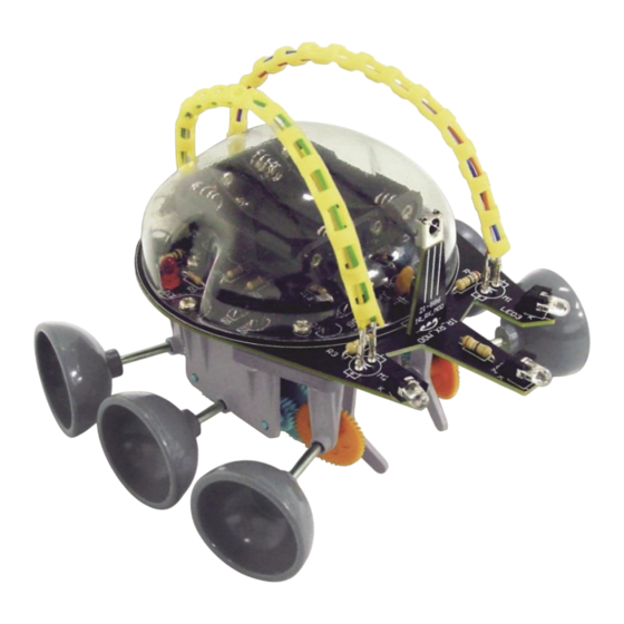
  • Seite 24 Roboter bewegt sich auf 6 Beinen. Der Bausatz wird mit 2 Sets von verschiedenen Beinen, die in ihrer Art bewegen, geliefert. Sie werden mit den verschiedenen Bewegungen endlos Spaß und Aufregung erleben. Der KSR4 braucht vier AAA-Batterien von 1.5V (nicht mitgeliefert). Sie brauchen auch noch einen Lötkolben, Lötzinn, eine Spitzzange, einen Seitenschneider und einen Schraubendreher.
  • Seite 25: Mechanische Stückliste (Siehe Abb. 2)

    KSR4 Mechanische Stückliste (siehe Abb. 2) 1. 2x Schraube P13 (3x6mm) 2. 4x Schraube P14 (3x6mm) 3. 2x Sclauch P18 4. 2x Mutter P16 (M3) 5. 2x hexag. Abstandbuchse P15 (10mm) 6. 1x Gehäuse P17 Montage Montage der Leiterplatte Montieren Sie zuerst die Widerstände. Die Namen der Komponenten stehen auf der Leiterplatte.
  • Seite 26 KSR4 Montieren Sie die LED, die IR-LEDs und die IC: Teil Beschreibung Menge LED1 LED 5mm (rot) LED2/3/4 IR LED 5mm (klar) + LED-Halter 3 + 3 Bemerkung: Montieren Sie das Empfangsmodul: (siehe Abb. 3) Teil Beschreibung Menge IR_RX_MOD IR-Empfangsmodul (Abb.1 #14) Montage Zahnradkasten Teile (siehe Abb.
  • Seite 27: Bedienung

    Schaltplan (siehe Abb.12) Bedienung Stellen Sie den Schalter in die “ON”-Position. LED1 wird brennen, das Gerät piepst 3x und der KSR4 fängt an zu laufen. Die Sendedioden LED2, LED3 und LED4 senden nacheinander Signale um Hindernisse zu entdecken. Wenn ein Hindernis detektiert wird, wird das empfangene Signal an das Empfangsmodul gesendet und welches den Befehl zum Ausweichen des Hindernisses gibt.
  • Seite 28: Instrukcja Obsługi

    Nie montować ani nie używać urządzenia, jeśli zostało uszkodzone podczas transportu - należy skontaktować się ze sprzedawcą. KSR4 działa jak inteligentny robot A.I. Zawsze znajduje drogę do wyjścia z labiryntu. Robot Escape wykorzystuje 3 diody emitujące podczerwień i 1 moduł odbiorczy IR, aby wysyłać i odbierać sygnały oraz wykrywać...
  • Seite 29 KSR4 Lista części mechanicznych (patrz rys. 2) 1. 2x śruba P13 (3x6mm) 2. 4x śruba P14 (3x6mm) 3. 2x kanał kablowy P18 4. 2x nakrętka P16 (M3) 5. 2x tulejka dystansowa 6-kątna P15 (10 mm) 6. 1x obudowa P17 Montaż...
  • Seite 30 KSR4 Zamontować diodę LED, diody LED IR oraz IC: ID części Opis Ilość LED1 LED 5mm (czerwona) LED2/3/4 LED IR 5mm (przezroczysta) + oprawka LED 3 + 3 UWAGA: Zamontować moduł odbiorczy IR (1x): ID części Opis Ilość IR_RX_MOD moduł odbiorczy IR (rys. 1, nr 14) Rys.
  • Seite 31: Wykrywanie I Usuwanie Usterek

    Schemat połączeń (patrz rys. 12) Obsługa Ustawić przełącznik w pozycji "ON". Świeci się dioda LED1, urządzenie emituje 3 sygnały dźwiękowe, a KSR4 zaczyna się przemieszczać. Diody emitujące podczerwień LED2, LED3 i LED4 wysyłają sekwencyjnie sygnały, aby wykryć przeszkody. Po wykryciu przeszkody otrzymany sygnał przesyłany jest do modułu odbiorczego, który następnie przekaże robotowi polecenie wykonania manewru wymijania.
  • Seite 32: Manual Do Utilizador

    O KSR4 funciona como um robor A.I. Encontra sempre o caminho para escapar de qualquer labirinto. O Robot Escape possui 3 diodos emissores de IV e 1 módulo de recepção de IV que lhe permite enviar e receber sinais e detectar obstáculos.
  • Seite 33 KSR4 Lista das Peças Mecânicas (ver figura 2) 1. 2x parafuso P13 (3x6mm) 2. 4x parafuso P14 (3x6mm) 3. 2x mangueira P18 4. 2x porca P16 (M3) 5. 2x poste hexagonal P15 (10mm) 6. 1x corpo P17 Montagem Montagem da Placa de Circuitos Impressos (PCB) Inicie a montagem começando por instalar os resistores.
  • Seite 34 KSR4 Monte o LED, os LEDs IR e o IC: ID da peça descrição quantidade LED1 LED 5mm (vermelho) LED2/3/4 LED IR mm (transparente) + suporte LED 3 + 3 OBSERVAÇÃO: Monte o módulo receptor IR (infravermelhos): ID da peça descrição...
  • Seite 35: Resolução De Problemas

    Diagrama da Cablagem Utilização Colocar o interruptor na posição "ON". O LED1 acende, o dispositivo emite 3 sinais sonoros e o KSR4 começa a andar. Os diodos emissores LED2, LED3 e LED4 enviam sinais em sequência para detectar obstáculos. Sempre que um obstáculo é...
  • Seite 36 Velleman®; worden. - se calcula gastos de transporte de y a Velleman® si el aparato ya no está • Bij reparaties buiten de waarborgperiode zullen transportkosten aangerekend cubierto por la garantía.
  • Seite 37 Velleman® Service- und Qualitätsgarantie wymienione wyżej warunki są bez uszczerbku dla wszystkich komercyjnych gwarancji. Seit der Gründung in 1972 hat Velleman® sehr viel Erfahrung als Verteiler in der Powyższe postanowienia mogą podlegać modyfikacji w zależności od Elektronikwelt in über 85 Ländern aufgebaut.

Inhaltsverzeichnis