OSRAM e:cue SYMPL input Node Installationsanleitung

Verwandte Anleitungen für OSRAM e:cue SYMPL input Node

Inhaltszusammenfassung für OSRAM e:cue SYMPL input Node
- Seite 1 Light is OSRAM Our Brand AB444200035 e:cue SYMPL input Node Setup Manual / Installationsanleitung...
-
Seite 22: Deutsch
Deutsch... -
Seite 23: Sicherheitshinweise
Das Gerät muss durch ein separates Class 2-Netzteil versorgt werden. Die maximale Länge jedes angeschlossenen Kabels beträgt 30 m. Sollte das beigelegte Heft mit den Sicherheitshinweisen fehlen, wenden Sie sich bitte an den OSRAM-Service für ein zusätzliches Exemplar. -
Seite 24: Gerätebeschreibung
Verbindungen zwischen Servern, Cores und Nodes erfolgen immer über e:net mittels Ethernet. Der e:cue SYMPL input Node ist ein achtkanaliges analoges Interface für die e:cue Steuerungslösung SYMPHOLIGHT. Er bietet acht unabhängige analoge 10 V-Eingänge, vier davon können auf 20 mA Konstantstrom umgeschaltet werden. -
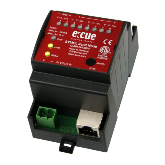
Seite 25: Anschlüsse Und Schnittstellen
Gerätebeschreibung 11.2 Anschlüsse und Schnittstellen Sicht von oben auf das Gerät Gemeinsame Masse Eingänge 0 ... 10 V (1 ... 4, links nach rechts) Eingänge 0 ... 10 V oder 0/4 ... 20 mA (5 ... 8, links nach rechts) Schiebeschalter Betriebsart Eingänge 5 ... -
Seite 26: Benutzeroberfläche: Leds
Fehler wie Kurzschluss der Datenanschlüsse. Schalten Sie das Gerät aus und wieder ein. Besteht der Fehler weiterhin, überprüfen Sie die Verdrahtung oder wenden Sie sich an den OSRAM Service. Status + Die Status- und die Error-LED blinken simultan, um den Error SYMPL Node zu identifizieren (aktiver “Identify Interface... -
Seite 27: Identify-Taster: Identifikation & Reset
Allgemeine Hinweise 11.4 Identify-Taster: Identifikation & Reset Der Identify-Taster hat zwei Funktionen: eine Identifizierungsnachricht verschicken (A) und das Gerät in den Auslieferungszustand zurücksetzen (B). (A) Kurzes Betätigen im Online-Zustand schickt eine Identifizierungsnachricht an SYMPHOLIGHT. Damit kann der Node im Layout zugeordnet werden. (B) Der Taster wird ebenso benutzt, um das Gerät in den Auslieferungszustand zurück zu setzen oder den Bootloader-Modus zu aktivieren:... -
Seite 28: Entpacken
Bewahren Sie die Verpackung für einen späteren Transport auf. Überprüfen Sie die Vollständigkeit des Lieferumfanges nach Kapitel „12.1 Lieferumfang“ auf Seite 24. Sollten Komponenten beschädigt sein oder fehlen, wenden Sie sich an Ihren OSRAM Support Service. 12.3 Garantiebestimmungen Abhängig vom Produkt können Garantie und Gewährleistung zeitlich... -
Seite 29: Technischer Support
33100 Paderborn, Deutschland +49 (5251) 54648-0 support@ecue.com 13 Installation Zur Installation vom e:cue SYMPL input Node montieren Sie diesen auf einer Hutschiene und schließen die Spannungsversorgung, eine e:net- Verbindung und Lasten an. Die Reihenfolge der Kabelanbindung ist beliebig. Schalten Sie die Stromversorgung erst an, wenn alle Kabel angeschlossen sind. -
Seite 30: Installationsbedingungen
Installation 13.1 Installationsbedingungen Installationsposition: Anschlüsse oben und unten Horizontalabstand: Kein Abstand notwendig Minimaler vertikaler Hutschienenabstand: 115 mm (90 + 25 mm) (ohne Kabelkanal) Empfohlener vertikaler 160 mm Hutschienenabstand: (mit 40 mm-Kabelkanal) Installationsort Innen (im Gebäude) 13.2 Montage Der SYMPL Node wird auf einer 35 mm-DIN-Hutschiene vertikal montiert (EN 60715). -
Seite 31: Eingangs-Verbindung
Installation stellen Sie das neue Node identisch zum alten Node ein. Anderenfalls funktioniert die Kommunikation mit SYMPHOLIGHT nicht. 13.5 Stromversorgung Verbinden Sei den e:cue SYMPL input Node mit einem NEC Class 2 24 V DC Netzteil. Das Anliegen von Stromversorgung am Node entspricht einem Anschalten des Gerätes. -
Seite 32: Netzwerk-Konfiguration
Class 2-Netzteil im Schaltschrank für die 24 V-Gleichspannungsversorgung. 14 Netzwerk-Konfiguration Die Konfiguration des e:cue SYMPL input Node erfolgt über e:cue SYMPHOLIGHT. Im SYMPHOLIGHT-Benutzerhandbuch finden Sie weitere Details. Das Benutzerhandbuch ist auf www.ecue.com verfügbar. Die Netzwerkeinstellungen des SYMPL input Nodes sind voreingestellt. Um Änderungen an den Netzwerkeinstellungen vornehmen zu können, ist die... -
Seite 33: Netzwerkeinstellung Über Sympholight
Netzwerk-Konfiguration Änderungen der Netzwerkeinstellungen können entweder in SYMPHOLIGHT oder über die Webschnittstelle des SYMPL input Nodes vorgenommen werden: 14.2 Netzwerkeinstellung über SYMPHOLIGHT Öffnen Sie in dem Setup Tab von SYMPHOLIGHT das Kontextmenü von dem SYMPL input Node mit einem Rechtsklick auf das Gerät. - Seite 34 Netzwerk-Konfiguration Webbrowser. Geben Sie in der Adressleiste die IP-Adresse des SYMPL input Nodes ein: z.B. http://192.168.123.1. Die Webschnittstelle des SYMPL input Nodes wird angezeigt: Klicken Sie “Configure”. Die Einstellungs-Seite wird angezeigt: Legen Sie die Netzwerkeinstellungen unter der Rubrik “Device Basics” nach Ihren Anforderungen fest. Sie können hier ebenfalls das Zugangspasswort zu den Webschnittstellen des SYMPL input Nodes ändern.
-
Seite 35: Firmware-Update
Knopf in der oberen Werkzeugleiste. 16 Demontage Um den e:cue SYMPL input Node abzubauen, trennen Sie alle verbundenen Kabel und Anschlüsse von dem Gerät. Entfernen Sie den SYMPL input Node von der Hutschiene, indem Sie die schwarze Hutschienen-Entriegelung ziehen und das Gerät von der Hutschiene lösen. -
Seite 36: Produktdaten
Produktdaten Vor der Demontage müssen geeignete Vorsichtsmaßnahmen ergriffen werden, um die entsprechenden Komponenten vor Schäden durch elektrostatische Entladung zu schützen (ESD-Schutz). 17 Produktdaten Bestellnummer AB444200035 Abmessungen (B x H x T) 53,5 x 90,5 x 62 mm (ohne Befestigungsclip) Gewicht 110 g Stromversorgung 24 V= auf Schraubanschluss... -
Seite 37: Zertifizierung
Maximale Eingangsspannung: 12 V= Maximaler Eingangsstrom: 30 mA 1 x gemeinsame Masse 18 Zertifizierung e:cue SYMPL input Node ist zertifiziert nach EN 55022, EN 55024, 62368-1 Ed. 2 Entspricht ANSI / UL Std. 60950-1 4000805 Zertifiziert nach CSA Std. C22.2 NO. 60950-1... -
Seite 40: Anwendungsbeispiele
Anwendungsbeispiele Mode switch for input set to 0 ... 20 mA. Mode switch set for input set to 0 ... 10 V. Sensor 0/4 ... 20 mA 2-wire Set mode switch for input 7 and 8 to 0/4 ... 20 mA/ Betriebsart für Eingang 7 und 8 mittels Schiebeschalter auf 0/4 ... - Seite 41 Sensor 0/4 ... 20 mA 3-wire Set mode switch for input 8 to 0/4 ... 20 mA/ Betriebsart für Eingang 8 mittels Schiebeschalter auf 0/4 ... 20 mA setzen. Sensor 4 ... 20 mA – Iout 12 V DC – With 3-wire sensors, all sensors can have the same power supply.
- Seite 42 Alle acht Eingänge sind für bis zu 12 V ausgelegt. 12 V DC – The mode switches have to be set to voltage input. Otherwise the e:cue SYMPL input Node might get damaged. Die Betriebsart muss auf Spannungs-Eingang gestellt sein. Anderenfalls kann der e:cue SYMPL input Node beschädigt werden.
- Seite 43 OSRAM GmbH Sales Operations Head office / Zentrale: Karl-Schurz-Str. 38 Marcel-Breuer-Strasse 6 33100 Paderborn, Germany 80807 Munich, Germany +49 5251 54648-0 Phone +49 89 6213-0 support@ecue.com Fax +49 89 6213-2020 www.ecue.com www.osram.com Light is OSRAM Our Brand...