Inhaltsverzeichnis
Werbung
Verfügbare Sprachen
Verfügbare Sprachen
Quicklinks
Werbung
Kapitel
Inhaltsverzeichnis

Inhaltszusammenfassung für STIEBEL ELTRON WPIC
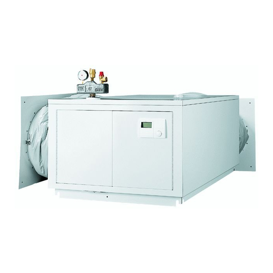
- Seite 1 BEDIENUNG UND INSTALLATION OPERATION AND INSTALLATION UTILISATION ET INSTALLATION USO E INSTALLAZIONE Funktionsmodul für Luft-Wasser-Wärmepumpe | Function module for air source heat pump | Module fonctionnel pour pompe à chaleur air-eau | Modulo funzionale per pompa di calore aria-acqua » WPIC...
-
Seite 2: Inhaltsverzeichnis
Wärmedämmung montieren ��������������������������������� 18 10.8 Funktionsmodul schließen ������������������������������������ 19 10.9 Luftführungsschläuche anschließen ������������������������ 19 Technische Daten ������������������������������������������� 20 11.1 Maße und Anschlüsse ����������������������������������������� 20 11.2 Elektroschaltplan ����������������������������������������������� 22 11.3 Datentabelle ����������������������������������������������������� 24 UMWELT UND RECYCLING KUNDENDIENST UND GARANTIE | WPIC www.stiebel-eltron.com... -
Seite 3: Allgemeine Hinweise
Tod zur Folge haben kann. triebnahme verantwortlich für die Einhaltung der geltenden VORSICHT Hinweise, deren Nichtbeachtung zu mittelschweren oder Vorschriften. leichten Verletzungen führen kann. - Betreiben Sie das Gerät nur komplett installiert und mit allen Sicherheitseinrichtungen. www.stiebel-eltron.com WPIC |... -
Seite 4: Prüfzeichen
Mit dem Funktionsmodul werden geliefert: - 1 x Verkleidungsteile der Wärmepumpe - 2 x Luftführungsschlauch - 1 x Außenfühler AF PT - 2 x Tauch- / Anlegefühler TAF PT - 1 x Dämmmatte - 2 x Dämmteil für Umwälzpumpe Anschlusszubehör - 2 x Druckschlauch | WPIC www.stiebel-eltron.com... -
Seite 5: Notwendiges Zubehör
Notwendiges Zubehör“). AWG 560 H Durch eine Außenwand ins Freie mit einer horizontalen Wanddurchführung 830-865 AWG 600 L Durch eine Kellerwand in einen Schacht mit einer Wanddurchführung 830-865 AWG 560 V Durch eine Außenwand ins Freie mit einer vertikalen Wanddurchführung 600-635 www.stiebel-eltron.com WPIC |... - Seite 6 INsTALLATIoN Vorbereitungen Luftführung ohne Schacht: Durch zwei Außenwände über Eck ≥300 ≥500 ≥900 Luftführung mit Schacht: Durch zwei Außenwände über Eck ≥600 ≥600 ≥300 ≥500 ≥1000 ≥900 | WPIC www.stiebel-eltron.com...
-
Seite 7: Hinweis Zur Bedienungs- Und Installationsanleitung
BUS-Leitung benötigen Sie ein Kabel J-Y (St) 2x2x0,8 mm². Sachschaden Sichern Sie die drei Stromkreise für das Gerät, die Steue- rung und die elektrische Not-/Zusatzheizung getrennt ab. Sachschaden Sichern Sie die Steuerleitung des Gerätes gemeinsam mit dem Wärmepumpen-Manager ab. www.stiebel-eltron.com WPIC |... -
Seite 8: Montage
Sie es mit zwei Schrauben. 2 Anschluss „Heizung Vorlauf“ f Kleben Sie das mitgelieferte Typenschild gut sichtbar vorn 3 Durchführung elektr. Leitungen oben auf die rechte Seitenwand des Funktionsmoduls. 4 Anschluss „Heizung Rücklauf“ 5 Anschluss „Speicher Rücklauf“ | WPIC www.stiebel-eltron.com... -
Seite 9: Umwälzpumpe
Beim Einstellen der Umwälzpumpe müssen Sie sicher- stellen, dass der Mindestvolumenstrom in allen Betriebs- punkten gewährleistet ist (siehe Kapitel „Technische Daten / Datentabelle“ in der Bedienungs- und Installati- onsanleitung der Wärmepumpe). f Verlegen Sie die elektrischen Leitungen wie in der Abbildung dargestellt. www.stiebel-eltron.com WPIC |... -
Seite 10: Anschluss Funktionsmodul
L1, L2, L3, N, PE Anschluss- Klemmenbelegung leistung 2,6 kW 3,0 kW 3,2 kW 5,6 kW 5,8 kW f Verbinden Sie die Litzen mit der Anschlussklemme X4. 6,2 kW 8,8 kW Anschluss BUS-Leitung Anschluss rohrbegleitheizung L, N, PE | WPIC www.stiebel-eltron.com... -
Seite 11: Anschluss Externer Komponenten
Funktionsmoduls anschließen, müssen Sie den „Stecker BUS-Leitung WP XD05“ und den „WP Netz XD01“ im X1.19 CAN (Anschluss für Wärmepumpe und Schaltkasten der Wärmepumpe angeschlossen haben CAN A Wärmepumpen-Erweiterung WPE) (siehe Kapitel „Technische Daten / Elektroschaltplan“). Netzspannung X2.1 Stromversorgung www.stiebel-eltron.com WPIC |... -
Seite 12: Wärmedämmung Montieren
Kleben Sie das Wärmedämmteil wie in der Abb. dargestellt Bei temporären Fehlern schaltet der Ausgang für eine über den Pumpenkopf. bestimmte Zeit das Signal durch. Bei Fehlern, die zu einer dauerhaften Abschaltung des Funktionsmodul schließen Gerätes führen, schaltet der Ausgang dauerhaft durch. | WPIC www.stiebel-eltron.com... -
Seite 13: Luftführungsschläuche Anschließen
BUS-Leitung benötigen Sie ein Kabel J-Y (St) 2x2x0,8 mm². Sachschaden Sichern Sie die drei Stromkreise für das Gerät, die Steue- rung und die elektrische Not-/Zusatzheizung getrennt ab. Sachschaden Sichern Sie die Steuerleitung des Gerätes gemeinsam mit dem Wärmepumpen-Manager ab. www.stiebel-eltron.com WPIC |... -
Seite 14: Montage
Öffnen Sie die rechte Klappe durch kräftiges Ziehen. 1 Druckschlauch Vorlauf 2 Druckschlauch Rücklauf f Schließen Sie die hydraulischen Anschlüsse an das Funkti- onsmodul. f Prüfen Sie den Steckverbinder an der Sicherheitsgruppe auf festen Sitz und Dichtheit. | WPIC www.stiebel-eltron.com... -
Seite 15: Umwälzpumpe
Klemmenbelegung Die Genehmigung des zuständigen Energieversorgungsunterneh- leistung mens zum Anschluss muss vorliegen. 2,6 kW 3,0 kW Hinweis 3,2 kW Beachten Sie die Anleitungen des Wärmepumpen-Mana- 5,6 kW gers und der Wärmepumpe. 5,8 kW 6,2 kW 8,8 kW www.stiebel-eltron.com WPIC |... - Seite 16 Die Steuerleitung und die BUS-Leitung verbinden das Funktions- modul mit dem Grundgerät der Wärmepumpe. 1 elektrische Verbindungsleitungen (BUS, Steuerspannung) 2 Anschlussbereich f Für die Anschlüsse müssen Sie den Vorschriften entspre- chende elektrische Leitungen verwenden. f Prüfen Sie die Funktion der Zugentlastungen. | WPIC www.stiebel-eltron.com...
- Seite 17 Schaltkasten der Wärmepumpe angeschlossen haben Masse (siehe Kapitel „Technische Daten / Elektroschaltplan“). X1.18 CAN (Anschluss für Fernbedienung FET und CAN B Internet Service Gateway ISG) X1.19 CAN (Anschluss für Wärmepumpe und CAN A Wärmepumpen-Erweiterung WPE) Netzspannung X2.1 Stromversorgung www.stiebel-eltron.com WPIC |...
-
Seite 18: Wärmedämmung Montieren
Bei temporären Fehlern schaltet der Ausgang für eine f Kleben Sie das Wärmedämmteil wie in der Abb. dargestellt bestimmte Zeit das Signal durch. über den Pumpenkopf. Bei Fehlern, die zu einer dauerhaften Abschaltung des Gerätes führen, schaltet der Ausgang dauerhaft durch. | WPIC www.stiebel-eltron.com... -
Seite 19: Funktionsmodul Schließen
Diese Luftschläuche sind hochflexibel, wärmegedämmt und haben ein selbstverlöschendes Brandverhalten. f Schließen Sie die Luftführungsschläuche mit den im Beipack enthaltenen Flügelschrauben an das Funktionsmodul an. f Verwenden Sie zum Anbringen der Luftführungsschläuche je nach Wandstruktur geeignete Dübel mit Schrauben. www.stiebel-eltron.com WPIC |... -
Seite 20: Technische Daten
11.1 Maße und Anschlüsse 300-500 300-500 1240 400 ±50 WPIC Durchführung elektr. Leitungen Sicherheitsgruppe Heizung Vorlauf Außengewinde G 1 1/4 Heizung Rücklauf Außengewinde G 1 1/4 Speicher Vorlauf Außengewinde G 1 1/4 Speicher Rücklauf Außengewinde G 1 1/4 Lufteintritt Luftaustritt | WPIC www.stiebel-eltron.com... - Seite 21 INsTALLATIoN Technische daten www.stiebel-eltron.com WPIC |...
-
Seite 22: Elektroschaltplan
X2.13 Kühlen AA01 X1.15 Analogeingang 0..10V AA01 X2.14 Mischer Heizkreis (X2.14.1 Mischer AUF/X2.14.2 Mischer ZU) AA01 X1.16 PWM Ausgang 1 AA01 X2.15 Mischer Heizkreis (X2.15.1 Mischer AUF/X2.15.2 Mischer ZU) AA01 X1.17 PWM Ausgang 2 AA06 XD27 Bedieneinheit | WPIC www.stiebel-eltron.com... - Seite 23 INsTALLATIoN Technische daten BT01 Temperaturfühler WP-Vorlauf Relais Motor-Umschaltventil MA14 Motor Pumpe MA15 Motor Umschaltventil XD01 WP Netz XD03 Netzanschlussklemme XD05 Stecker BUS-Leitung WP XD20 Steck-Schraubklemmleiste 3-pol www.stiebel-eltron.com WPIC |...
-
Seite 24: Datentabelle
Materialien erreicht, um Deponien und die Umwelt zu ent- lasten. Damit leisten wir gemeinsam einen wichtigen Beitrag zum Umweltschutz. Entsorgung außerhalb Deutschlands Entsorgen Sie dieses Gerät fach- und sachgerecht nach den örtlich geltenden Vorschriften und Gesetzen. | WPIC www.stiebel-eltron.com... -
Seite 25: Kundendienst Und Garantie
Feuer, Aufruhr oder ähnliche Ursachen. oder schreiben Sie uns: Über die vorstehend zugesagten Garantieleistungen hinausge- Stiebel Eltron GmbH & Co. KG hend kann der Endkunde nach dieser Garantie keine Ansprüche - Kundendienst - wegen mittelbarer Schäden oder Folgeschäden, die durch das Fürstenberger Straße 77, 37603 Holzminden... - Seite 26 10.8 Closing the function module ��������������������������������� 42 10.9 Connecting the air hoses �������������������������������������� 42 Specification ������������������������������������������������ 43 11.1 Dimensions and connections ��������������������������������� 43 11.2 Wiring diagram ������������������������������������������������� 44 11.3 Data table �������������������������������������������������������� 46 GUARANTEE ENVIRONMENT AND RECYCLING | WPIC www.stiebel-eltron.com...
-
Seite 27: General Information
Children must never play with the appliance. Cleaning and user maintenance must not be carried out by children without supervision. www.stiebel-eltron.com WPIC |... -
Seite 28: Test Symbols
- 2 x Air guide hose - 1 x Outside sensor AF PT - 2 x TAF PT immersion/contact sensor - 1 x Insulating mat - 2 x Insulation section for circulation pump Connection accessories - 2 x Pressure hose | WPIC www.stiebel-eltron.com... -
Seite 29: Required Accessories
Through an external wall to the outdoors with a horizontal wall outlet 830-865 AWG 600 L Through a cellar wall in a shaft with a wall outlet 830-865 AWG 560 V Through an external wall to the outdoors with a vertical wall outlet 600-635 www.stiebel-eltron.com WPIC |... - Seite 30 INsTALLATIoN Preparation Air routing without a shaft: Through two external walls around a corner ≥300 ≥500 ≥900 Air routing with a shaft: Through two external walls around a corner ≥600 ≥600 ≥300 ≥500 ≥1000 ≥900 | WPIC www.stiebel-eltron.com...
-
Seite 31: Note On The Operating And Installation Instructions
Material losses Provide separate fuses/MCBs for the three power circuits, i.e. those of the appliance, the control unit and the elec- tric emergency/booster heater. Material losses Provide common fuses/MCBs for the appliance control cable and the heat pump manager. www.stiebel-eltron.com WPIC |... -
Seite 32: Installation
9.2.2 Opening the function module 1 Pressure hose for return 2 Pressure hose for flow f Use suitable gaskets. f Guide the pressure hose connections through the aperture. f Remove the locking screw. | WPIC www.stiebel-eltron.com... -
Seite 33: Circulation Pump
Fit the drain pipe of the safety valve with a constant fall. f Ensure that the drain connection of the safety valve is open to the outside. f Route the cables as shown in the diagram. f Connect the cables according to the following diagram. www.stiebel-eltron.com WPIC |... - Seite 34 X5 electric emergency/booster heater power supply ("dHC") L1, L2, L3, N, PE Connected Terminal assignment load 2.6 kW 3.0 kW 3.2 kW 5.6 kW 5.8 kW 6.2 kW 8.8 kW ribbon heater connection f Connect the wires to terminal X4. L, N, PE Bus cable connection | WPIC www.stiebel-eltron.com...
-
Seite 35: Connecting External Components
(see chapter CAN B ISG Internet Service Gateway) "Specification / Wiring diagram"). X1.19 CAN (connection for heat pump and WPE heat CAN A pump extension) Mains voltage X2.1 Power supply www.stiebel-eltron.com WPIC |... -
Seite 36: Fitting The Thermal Insulation
In the case of temporary faults, the output switches the signal through for a specific time. Closing the function module In the case of faults that result in a permanent appliance shutdown, the output switches through permanently. | WPIC www.stiebel-eltron.com... -
Seite 37: Connecting The Air Hoses
Material losses Provide separate fuses/MCBs for the three power circuits, i.e. those of the appliance, the control unit and the elec- tric emergency/booster heater. Material losses Provide common fuses/MCBs for the appliance control cable and the heat pump manager. www.stiebel-eltron.com WPIC |... -
Seite 38: Installation
Open the right-hand flap by pulling it firmly. 1 Flow pressure hose 2 Return pressure hose f Connect the hydraulic connections to the function module. f Check that the push-fit connector on the safety assembly is firmly attached and is not leaking. | WPIC www.stiebel-eltron.com... -
Seite 39: Circulation Pump
X3 electric emergency/booster heater power supply ("dHC") the relevant power supply utility. L1, L2, L3, N, PE Connected Terminal assignment Note load Follow the instructions for the heat pump manager and 2.6 kW the heat pump. 3.0 kW 3.2 kW 5.6 kW 5.8 kW 6.2 kW 8.8 kW www.stiebel-eltron.com WPIC |... - Seite 40 1 Connecting cables (bus, control voltage) 2 Terminal area f For all connections, use appropriate cables in accordance with local regulations. f Check that the strain relief fittings are working as intended. | WPIC www.stiebel-eltron.com...
- Seite 41 CAN A X2.3 Heating circuit pump 1 X2.4 Heating circuit pump 2 X2.5 Heating circuit pump 3 X2.6 Buffer charging pump 1 X2.1 X2.2 X2.3 X2.4 X2.5 X2.6 X2.7 X2.8 X2.9 X2.10 X2.11 X2.12 X2.13 X2.14 X2.15 www.stiebel-eltron.com WPIC |...
-
Seite 42: Fitting The Thermal Insulation
Use rawl plugs and screws that are suitable for the wall structure to attach the air hoses. | WPIC www.stiebel-eltron.com... -
Seite 43: Specification
Entry electrical cables Safety assembly Heating flow Male thread G 1 1/4 Heating return Male thread G 1 1/4 Cylinder flow Male thread G 1 1/4 Cylinder return Male thread G 1 1/4 Air intake Air discharge www.stiebel-eltron.com WPIC |... -
Seite 44: Wiring Diagram
FE7 remote control AA01 X1.14 Analogue input 0-10 V AA01 X2.13 Cooling AA01 X1.15 Analogue input 0-10 V AA01 X2.14 Mixer, heating circuit (X2.14.1 mixer OPEN / X2.14.2 mixer CLOSE) AA01 X1.16 PWM output 1 AA01 X1.17 PWM output 2 | WPIC www.stiebel-eltron.com... - Seite 45 Programming unit BT01 Heat pump flow temperature sensor Motorised diverter valve relay MA14 Pump motor MA15 Diverter valve motor XD01 Heat pump mains XD03 Mains terminal XD05 Heat pump bus cable connector XD20 3-pole screw-type plug-in terminal strip www.stiebel-eltron.com WPIC |...
-
Seite 46: Data Table
This will not affect warranties issued by any importers. Environment and recycling We would ask you to help protect the environment. After use, dispose of the various materials in accordance with national regulations. | WPIC www.stiebel-eltron.com... - Seite 47 Fermeture du module fonctionnel �������������������������� 64 10.9 Raccordement de gaines de conduite d’air ���������������� 64 Données techniques ��������������������������������������� 65 11.1 Cotes et raccordements ���������������������������������������� 65 11.2 Schéma électrique ���������������������������������������������� 66 11.3 Tableau de données �������������������������������������������� 68 GARANTIE PROTECTION DE L’ENVIRONNEMENT ET RECYCLAGE www.stiebel-eltron.com WPIC |...
-
Seite 48: Remarques Générales
- N’utilisez cet appareil que s’il est installé dans son intégralité ner de graves lésions, voire la mort. ATTENTION Caractérise des consignes dont le non-respect peut entraî- et doté de tous les dispositifs de sécurité. ner des lésions légères ou moyennement graves. | WPIC www.stiebel-eltron.com... -
Seite 49: Label De Conformité
- 2 x flexibles de guidage d’air - 1 x Sonde extérieure AF PT - 2 x Sonde à applique / plongeuse TAF PT - 1 x Natte isolante - 2 x Élément isolant pour le circulateur Accessoires de raccordement - 2 x Tuyau anti-vibratoire www.stiebel-eltron.com WPIC |... -
Seite 50: Accessoires Nécessaires
Pour pratiquer un passage dans le mur d’une cave donnant sur une cheminée d’aération avec une traversée murale 830-865 AWG 560 V Pour pratiquer un passage vers l’air libre dans un mur extérieur avec une traversée murale verticale 600-635 | WPIC www.stiebel-eltron.com... - Seite 51 Travaux préparatoires Circulation de l’air sans cheminée d’aération : à travers deux murs extérieurs en angle ≥300 ≥500 ≥900 Circulation de l’air avec cheminée d’aération : à travers deux murs extérieurs en angle ≥600 ≥600 ≥300 ≥500 ≥1000 ≥900 www.stiebel-eltron.com WPIC |...
-
Seite 52: Remarque Au Sujet Des Instructions D'utilisation Et D'installation
à chaleur. Un câble J-Y (St) 2 x 2 x 0,8 mm² est requis pour la ligne BUS. Dommages matériels Protégez séparément les trois circuits électriques de l’ap- pareil, de la commande et de la résistance électrique d’appoint / de secours. | WPIC www.stiebel-eltron.com... -
Seite 53: Montage
Placez le module fonctionnel sur la pompe à chaleur et fixez celui-ci à l’aide de deux vis. f Collez de manière bien visible la plaque signalétique fournie sur le devant, en haut de la paroi latérale droite du module fonctionnel. www.stiebel-eltron.com WPIC |... -
Seite 54: Circulateur
(voir le chapitre « Données techniques / Tableau de données » dans les instructions d’utilisation et d’installation de la pompe à chaleur). f Posez les câbles électriques de la façon indiquée sur le sché- f Raccordez les câbles électriques selon le schéma ci-dessous. | WPIC www.stiebel-eltron.com... - Seite 55 (dHC) L1, L2, L3, N, PE Puissance Affectation des bornes raccordée 2,6 kW 3,0 kW 3,2 kW 5,6 kW 5,8 kW 6,2 kW 8,8 kW raccordement du fil traçant chauffant f Raccordez les fils conducteurs au bornier de raccordement L, N, PE www.stiebel-eltron.com WPIC |...
- Seite 56 2e générateur de chaleur (2e WE) Masse X1.11 Signal Départ refroidissement Masse X1.12 Signal Sonde de circulation Masse X1.13 Signal Commande à distance FE7 / télérupteur té- Masse léphonique / optimisation de la courbe de Signal chauffe / SG Ready | WPIC www.stiebel-eltron.com...
-
Seite 57: Pose De L'isolation Thermique
( X2.14.1 Vanne mélangeuse OU- VERTE Vanne mélan- X2.14.2 Vanne mélangeuse FERMÉE ) geuse FERMÉE X2.15 Vanne mélan- Vanne mélangeuse circuit de chauf- geuse OUVERTE fage 3 ( X2.15.1 Vanne mélangeuse OU- VERTE Vanne mélan- X2.15.2 Vanne mélangeuse FERMÉE ) geuse FERMÉE www.stiebel-eltron.com WPIC |... -
Seite 58: Fermeture Du Module Fonctionnel
à chaleur. Un câble J-Y (St) 2 x 2 x 0,8 mm² est requis pour la ligne BUS. Dommages matériels Protégez séparément les trois circuits électriques de l’ap- pareil, de la commande et de la résistance électrique d’appoint / de secours. | WPIC www.stiebel-eltron.com... -
Seite 59: Montage
Vérifiez que le manchon rapide sur le groupe de sécurité est f Retirez la vis de sûreté. solidement fixé et étanche. f Tirez le levier vers l’avant. Le battant gauche s’ouvre. f Ouvrez le battant droit en tirant avec force. www.stiebel-eltron.com WPIC |... -
Seite 60: Circulateur
Il est nécessaire de posséder l’autorisation de raccordement ac- raccordée cordée par la société distributrice d’électricité compétente. 2,6 kW 3,0 kW 3,2 kW Remarque 5,6 kW Tenez compte des notices du gestionnaire de pompe à 5,8 kW chaleur et de la pompe à chaleur. 6,2 kW 8,8 kW | WPIC www.stiebel-eltron.com... - Seite 61 1 Câbles de raccordement électrique (BUS, tension de commande) 2 Zone de raccordement f Pour les raccordements, il convient d’utiliser des câbles élec- triques conformes à la réglementation applicable. f Contrôlez le bon fonctionnement des dispositifs anti-traction. www.stiebel-eltron.com WPIC |...
- Seite 62 (voir le chapitre « Données techniques / Schéma CAN B tance FET et de la passerelle Internet Service électrique »). Gateway ISG) X1.19 CAN (branchement de la pompe à chaleur et CAN A de l’extension de pompe à chaleur WPE) | WPIC www.stiebel-eltron.com...
-
Seite 63: Pose De L'isolation Thermique
En cas de défaut de l’appareil, la sortie X2.10 active un signal 230 V. En cas de défauts temporaires, la sortie transmet le signal pendant une durée déterminée. En cas de défauts provoquant un arrêt continu de l’appa- reil, la sortie est activée en permanence. www.stiebel-eltron.com WPIC |... -
Seite 64: Fermeture Du Module Fonctionnel
Raccordez les gaines de conduite d’air au module fonctionnel avec les vis à ailettes fournies. f Utilisez des chevilles et vis appropriées à la structure du mur sur lequel vous allez poser les gaines de conduite d’air. | WPIC www.stiebel-eltron.com... -
Seite 65: Données Techniques
Passage des câbles électriques Groupe de sécurité Départ chauffage Filetage mâle G 1 1/4 Retour chauffage Filetage mâle G 1 1/4 Départ ballon Filetage mâle G 1 1/4 Retour ballon Filetage mâle G 1 1/4 Aspiration d’air Refoulement d’air www.stiebel-eltron.com WPIC |... -
Seite 66: Schéma Électrique
Entrée analogique 0...10 V AA01 X2.13 Refroidissement AA01 X1.15 Entrée analogique 0...10 V AA01 X2.14 Vanne mélangeuse circ. chauf. (X2.14.1 vanne mél. OU- VERTE/X2.14.2 vanne mél. FERMÉE) AA01 X1.16 Sortie MLI 1 AA01 X1.17 Sortie MLI 2 | WPIC www.stiebel-eltron.com... - Seite 67 Sonde de température départ eau pompe à chaleur Relais moteur soupape d’inversion MA14 Moteur pompe MA15 Moteur soupape d’inversion XD01 PAC réseau XD03 Bornier de raccordement au secteur XD05 Fiche câble Bus PAC XD20 Barrette à 3 broches à enficher www.stiebel-eltron.com WPIC |...
-
Seite 68: Tableau De Données
D’éventuelles garanties accordées par l’importa- teur restent inchangées. Environnement et recyclage Merci de contribuer à la préservation de notre environnement. Après usage, procédez à l’élimination des matériaux conformé- ment à la réglementation nationale. | WPIC www.stiebel-eltron.com... - Seite 69 Chiusura del modulo funzionale ����������������������������� 86 10.9 Collegamento dei condotti di presa d'aria ����������������� 86 Dati tecnici �������������������������������������������������� 87 11.1 Misure e allacciamenti ����������������������������������������� 87 11.2 Schema elettrico ������������������������������������������������ 88 11.3 Tabella dei dati �������������������������������������������������� 90 GARANZIA TUTELA DELL'AMBIENTE E RICICLAGGIO www.stiebel-eltron.com WPIC |...
-
Seite 70: Avvertenze Generali
CAUTELA Note che, se non osservate, possono causare lesioni me- dell'apparecchio. dio-gravi o lievi. - Usare l'apparecchio solo a installazione completata e con tutti i dispositivi di sicurezza. | WPIC www.stiebel-eltron.com... -
Seite 71: Marchio Di Collaudo
- 2 condotti di presa d'aria - 1 Sensore esterno AF PT - 2 Sensore a immersione / a contatto TAF PT - 1 Tappetino isolante - 2 Elemento isolante per la pompa di circolazione Accessori di allacciamento - 2 Tubo a pressione www.stiebel-eltron.com WPIC |... -
Seite 72: Accessori Necessari
Attraverso una parete esterna verso l'esterno, con un passaggio a parete orizzontale 830-865 AWG 600 L Attraverso una parete della cantina in un condotto con un passaggio a parete 830-865 AWG 560 V Attraverso una parete esterna verso l'esterno, con un passaggio a parete verticale 600-635 | WPIC www.stiebel-eltron.com... - Seite 73 INsTALLAZIoNe operazioni preliminari Canalizzazione dell'aria senza condotto: attraverso due pareti esterne ad angolo ≥300 ≥500 ≥900 Canalizzazione dell'aria con condotto: attraverso due pareti esterne ad angolo ≥600 ≥600 ≥300 ≥500 ≥1000 ≥900 www.stiebel-eltron.com WPIC |...
-
Seite 74: Nota Sulle Istruzioni Di Installazione E Uso
J-Y (St) 2x2x0,8 mm² schermato. Danni materiali Proteggere separatamente i tre circuiti elettrici per appa- recchio, comando e riscaldatore booster supplementare/ di emergenza. Danni materiali Proteggere il cavo di controllo dell'apparecchio assieme al quadretto di comando. | WPIC www.stiebel-eltron.com... -
Seite 75: Installazione
2 Allacciamento "Riscaldamento mandata" f Incollare la targhetta di identificazione fornita, in posizione 3 Passaggio cavi elettrici ben visibile, in alto sul davanti del pannello laterale destro 4 Allacciamento "Riscaldamento ritorno" del modulo funzionale. 5 Allacciamento "Accumulatore ritorno" www.stiebel-eltron.com WPIC |... -
Seite 76: Pompa Di Circolazione
(vedere il capitolo "Dati tecnici / Tabella dei dati" nelle Istruzioni di installazione e uso della pompa di calore). f Posare i cavi elettrici come mostrato in figura. | WPIC www.stiebel-eltron.com... - Seite 77 L1, L2, L3, N, PE Potenza al- Assegnazione dei morsetti lacciata 2,6 kW 3,0 kW 3,2 kW 5,6 kW 5,8 kW f Collegare i cavetti al morsetto X4. 6,2 kW 8,8 kW Allacciamento del cavo BUS Allacciamento del riscaldamento ausiliario per tubazioni L, N, PE www.stiebel-eltron.com WPIC |...
- Seite 78 PDC XD05" e la "PDC rete XD01" nella scatola interrut- tori della pompa di calore (vedere il capitolo "Dati tecnici / Schema elettrico"). X1.19 CAN (allacciamento per pompa di calore e am- CAN A pliamento per pompa di calore WPE) | WPIC www.stiebel-eltron.com...
-
Seite 79: Montaggio Dell'isolamento Termico
Per ogni errore sull'apparecchio, l'uscita X2.10 invia un segnale 230 V. In caso di errori temporanei, l'uscita inserisce il segnale per un determinato intervallo. In presenza di errori che causano uno spegnimento con- tinuo dell'apparecchio, anche l'uscita si inserisce conti- nuamente. www.stiebel-eltron.com WPIC |... -
Seite 80: Collegamento Dei Condotti Di Presa D'aria
J-Y (St) 2x2x0,8 mm² schermato. Danni materiali Proteggere separatamente i tre circuiti elettrici per appa- recchio, comando e riscaldatore booster supplementare/ di emergenza. Danni materiali Proteggere il cavo di controllo dell'apparecchio assieme al quadretto di comando. | WPIC www.stiebel-eltron.com... -
Seite 81: Installazione
1 Tubo in pressione di mandata f Aprire il coperchio destro tirando con forza. 2 Tubo in pressione di ritorno f Collegare gli allacci idraulici al modulo funzionale. f Controllare il corretto fissaggio e la tenuta del connettore sul gruppo di sicurezza. www.stiebel-eltron.com WPIC |... -
Seite 82: Pompa Di Circolazione
2,6 kW È necessario disporre dell'autorizzazione dell'azienda di fornitura 3,0 kW dell'energia elettrica per l'allacciamento. 3,2 kW 5,6 kW 5,8 kW Nota 6,2 kW Attenersi alle istruzioni del quadretto di comando della 8,8 kW pompa di calore e a quelle della pompa di calore. | WPIC www.stiebel-eltron.com... - Seite 83 1 Cavi elettrici di collegamento (BUS, tensione di comando) 2 Zona di allaccio f Per gli allacciamenti è necessario utilizzare conduttori elet- trici conformi alle prescrizioni. f Verificare la funzionalità delle fascette di fissaggio. www.stiebel-eltron.com WPIC |...
- Seite 84 Uscita PWM 2 / Schema elettrico"). Massa X1.18 CAN (allacciamento per controllo remoto FET e CAN B Internet Service Gateway ISG) X1.19 CAN (allacciamento per pompa di calore e am- CAN A pliamento per pompa di calore WPE) | WPIC www.stiebel-eltron.com...
-
Seite 85: Montaggio Dell'isolamento Termico
Per ogni errore sull'apparecchio, l'uscita X2.10 invia un segnale 230 V. In caso di errori temporanei, l'uscita inserisce il segnale per un determinato intervallo. In presenza di errori che causano uno spegnimento con- tinuo dell'apparecchio, anche l'uscita si inserisce conti- nuamente. www.stiebel-eltron.com WPIC |... -
Seite 86: Chiusura Del Modulo Funzionale
Collegare i condotti di presa d'aria al modulo funzionale usando le viti ad alette contenute nell'imballo. f Per l'applicazione dei condotti di presa d'aria utilizzare tas- selli con viti che siano adatti alla struttura del muro. | WPIC www.stiebel-eltron.com... -
Seite 87: Dati Tecnici
Filettatura di tipo maschio G 1 1/4 Riscaldamento ritorno Filettatura di tipo maschio G 1 1/4 Accumulatore mandata Filettatura di tipo maschio G 1 1/4 Accumulatore ritorno Filettatura di tipo maschio G 1 1/4 Entrata aria Uscita aria www.stiebel-eltron.com WPIC |... -
Seite 88: Schema Elettrico
Controllo remoto FE7 AA01 X1.14 Ingresso analogico da 0..10V AA01 X2.13 Raffrescamento AA01 X1.15 Ingresso analogico da 0..10V AA01 X2.14 Miscelatore circuito di riscaldamento (X2.14.1 miscelatore aperto/X2.14.2 miscelatore chiuso) AA01 X1.16 Uscita PWM 1 AA01 X1.17 Uscita PWM 2 | WPIC www.stiebel-eltron.com... - Seite 89 BT01 Sonda temperatura di mandata PDC Relè motore valvola di commutazione MA14 Motore pompa MA15 Motore valvola di commutazione XD01 PDC rete XD03 Morsetto di allacciamento alla rete XD05 Spina cavo BUS PDC XD20 Morsettiera 3 poli www.stiebel-eltron.com WPIC |...
-
Seite 90: Tabella Dei Dati
Tensione di alimentazione comando Fasi comando 1/N/PE Fusibile comando Frequenza Versioni Tipo di protezione (IP) IP1XB Modello pompa di circolazione Pompa di circolazione ad alta efficienza integrata Dimensioni Altezza Larghezza 1240 Profondità Diametro tubo aria Pesi Peso | WPIC www.stiebel-eltron.com... -
Seite 91: Garanzia
Restano invariate eventuali garanzie prestate dall’im- portatore. Ambiente e riciclaggio Aiutateci a salvaguardare il nostro ambiente. Dopo l’uso, smal- tire i materiali in conformità con le prescrizioni nazionali in vi- gore. www.stiebel-eltron.com WPIC |... - Seite 92 Deutschland Verkauf Tel. 05531 702-110 | Fax 05531 702-95108 | info-center@stiebel-eltron.de STIEBEL ELTRON GmbH & Co. KG Kundendienst Tel. 05531 702-111 | Fax 05531 702-95890 | kundendienst@stiebel-eltron.de Dr.-Stiebel-Straße 33 | 37603 Holzminden Ersatzteilverkauf Tel. 05531 702-120 | Fax 05531 702-95335 | ersatzteile@stiebel-eltron.de Tel.