Herunterladen Inhalt Inhalt Diese Seite drucken
Inhaltsverzeichnis

Werbung

Verfügbare Sprachen

Verfügbare Sprachen

PMV Kit
Kit PMV
PMV-Kit
Kit PMV
Juego PMV
Kit PMV
PMV-Set
PMV Kit
PMV
RBM-PMV0361E
RBM-PMV0901E
INSTALLATION MANUAL
MANUEL D’INSTALLATION
INSTALLATIONS-HANDBUCH
MANUALE DI INSTALLAZIONE
MANUAL DE INSTALACIÓN
MANUAL DE INSTALAÇÃO
INSTALLATIEHANDLEIDING
ÅÃ×ÅÉÑÉÄÉÏ ÅÃÊÁÔÁÓÔÁÓÇÓ

Werbung

Inhaltsverzeichnis
loading

Inhaltszusammenfassung für Toshiba RBM-PMV0361E

  • Seite 1 INSTALLATION MANUAL MANUEL D’INSTALLATION INSTALLATIONS-HANDBUCH MANUALE DI INSTALLAZIONE MANUAL DE INSTALACIÓN MANUAL DE INSTALAÇÃO INSTALLATIEHANDLEIDING ÅÃ×ÅÉÑÉÄÉÏ ÅÃÊÁÔÁÓÔÁÓÇÓ PMV Kit Kit PMV PMV-Kit Kit PMV Juego PMV Kit PMV PMV-Set PMV Kit RBM-PMV0361E RBM-PMV0901E...
  • Seite 2 Dank u voor het aankopen van de TOSHIBA Mini-SMMS Air Conditioner. TOEPASSING VAN EEN NIEUW KOELMIDDEL Leest u deze handleiding zorgvuldig door voor u de Flow Selector- eenheid.
  • Seite 3: Inhaltsverzeichnis

    CONTENTS Accessory parts and Parts to be procured locally ......1 REFRIGERANT PIPING ..............7 PRECAUTIONS FOR SAFETY ............1 FIXATION AFTER CONNECTION PIPES ........10 INSTALLATION OF NEW REFRIGERANT AIR CONDITIONER ..3 ELECTRIC WORK ................11 SELECTION OF INSTALLATION PLACE ........4 SETUP OF OUTDOOR UNIT ............
  • Seite 4: Accessory Parts And Parts To Be Procured Locally

    Accessory parts and Parts to be procured locally Accessory parts Q’ty RBM- Part name Shape Usage PMV0361E PMV0901E Installation Manual Connection cable and UPPER OUTDOOR INDOOR Connector conversion cable Connecting cable for PMV control UNIT SIDE UNIT SIDE (Connected to PMV Kit) For heat insulating of liquid pipe Heat insulating pipe connection section...
  • Seite 5 WARNING • Ask an authorized dealer or qualified installation professional to install/maintain the air conditioner. Inappropriate installation may result in water leakage, electric shock or fire. • Turn off the main power supply switch or breaker before attempting any electrical work. Make sure all power switches are off.
  • Seite 6: Installation Of New Refrigerant Air Conditioner

    INSTALLATION OF NEW REFRIGERANT AIR CONDITIONER This PMV Kit adopts the new HFC refrigerant (R410A) which does not deplete the ozone layer. • R410A refrigerant is apt to be affected by impurity such as water, oxidizing membrane, or oils because the pressure of R410A refrigerant is higher than that of the former refrigerant by approx.
  • Seite 7: Selection Of Installation Place

    SELECTION OF INSTALLATION PLACE CAUTION Do not install the air conditioner at place where combustible gas may leak. If gas leaks and is collected at surrounding the unit, the production of fire may be caused. Upon customer’s approval, install the air conditioner at a place where satisfies the following conditions.
  • Seite 8: Installation Space

    • Keep a clearance of 50mm or more between the top panel of the unit and the ceiling. • The length of a connection pipe to the indoor unit should be 2 m to 10 m. Installation space RBM-PMV0361E, RBM-PMV0901E Box cover 200 or more...
  • Seite 9: Inatallation Of Pmv Kit

    INATALLATION OF PMV KIT WARNING Install the unit securely in the place to sufficiently withstand the weight of the unit. If the foundation is not sturdy enough, the unit may fall and cause personal injury. Perform a specified installation work to guard against earth quake. Improper installation may cause the unit to fall.
  • Seite 10: Refrigerant Piping

    Piping material and dimensions Model name Indoor unit capacity type Diameter of refrigerant pipe Notes RBM-PMV0361E 007, 009, 012 type Ø6.4 015, 018 type Ø6.4 RBM-PMV0901E Attached joint...
  • Seite 11 Pipe forming/End positioning Connection of refrigerant pipe Connect all the refrigerant pipes with flare connecting Flaring work. 1. Cut the pipe with a pipe cutter. • Since the atmospheric pressure only is sealed as the sealing gas, it is not abnormal that “Pushu…” sound is not heard when the flare nut is removed.
  • Seite 12 REFRIGERANT PIPING Airtight test/Air purge, etc. For airtight test, air purge, addition of refrigerant, and gas leak check, follow the Installation Manual attached to the outdoor unit. REQUIREMENT Be sure to use the tool such as charge hose exclusive to R410A. Do not turn on the power until the airtight test and the vacuuming have finished.
  • Seite 13: Fixation After Connection Pipes

    FIXATION AFTER CONNECTION PIPES 1. After connection to pipes, fix the PMV Kit using the attached binding band so that it is held closely to the gas pipe. Binding band L Binding band M Binding band M Binding band M Binding band L Binding band M Refrigerant pipe...
  • Seite 14: Electric Work

    ELECTRIC WORK WARNING 1. Using the specified wires, ensure to connect the wires, and fix wires securely so that the external strength of the wires do not transmit to the connecting part of the terminals. Incomplete connection or fixation may cause fire, etc. 2.
  • Seite 15: Work Procedure 1 (In Case Of Indoor Unit Which Connector Conversion Cable Is Not Used)

    • Work procedure 1 (In case of indoor unit which connector conversion cable is not used) 1) Turn on power supply of the indoor unit only and open fully the pulse motor valve built in the indoor unit. Turn on power supply of the indoor unit only under condition that power supply of the outdoor unit is OFF. ∗...
  • Seite 16: Setup Of Outdoor Unit

    ELECTRIC WORK • Work procedure 2 (In case of indoor unit which connector conversion cable is used) The work procedures from 1) to 3) are same to those in the work procedure 1. 4) Join and add the connector conversion cable to the connection cable (11m) which is out of PMV Kit box. 5) When the product was shipped from the factory, PMV connector built in the indoor unit is connected to CN82 connector of the indoor control PC board of the indoor unit.
  • Seite 17: Pièces Annexes Et Pièces À Se Procurer Localement

    Pièces annexes et Pièces à se procurer localement Pièces annexes Quantité RBM- Nom de la pièce Forme Utilisation PMV0361E PMV0901E Manuel d’installation Câble de branchement et câble Câble de branchement pour UPPER OUTDOOR INDOOR de conversion du connecteur UNIT SIDE UNIT SIDE commande PMV (Branché...
  • Seite 18 PRÉCAUTIONS POUR LA SÉCURITÉ AVERTISSEMENT • Pour l’installation de votre climatisation, adressez-vous à un distributeur agréé ou à un installateur professionnel. Une installation inappropriée peut entraîner des fuites d’eau, des électrocutions ou un incendie. • Coupez l’interrupteur de l’alimentation principale (ou le disjoncteur) avant d’effectuer tout travail électrique. Veillez à...
  • Seite 19: Installation De La Climatisation À Nouveau Réfrigérant

    INSTALLATION DE LA CLIMATISATION À NOUVEAU RÉFRIGÉRANT Ce Kit PMV utilise le nouveau réfrigérant HFC (R410A), qui ne détruit pas la couche d’ozone. • Le réfrigérant R410A est susceptible d’être perturbé par des impuretés comme de l’eau, des membranes oxydantes ou de l’huile, ceci en raison d’une pression plus élevée que celle des réfrigérants précédents, environs 1.6 fois plus.
  • Seite 20: Choix De L'emplacement D'installation

    CHOIX DE L’EMPLACEMENT D’INSTALLATION ATTENTION N’installez pas la climatisation dans un emplacement susceptible d’être exposé à une fuite de gaz combustible. En cas de fuite de gaz combustible et d’accumulation de ce gaz autour de l’unité, un incendie peut se déclencher. Sur consentement du client, installez la climatisation à...
  • Seite 21: Espace D'installation

    • Gardez un dégagement de 50 mm ou plus entre le panneau supérieur de l’unité et le plafond. • La longueur du tuyau de raccordement sur l’unité intérieure doit être comprise entre 2 et 10 m. Espace d’installation RBM-PMV0361E, RBM-PMV0901E Couvercle 200 ou davantage 200 ou davantage du boîtier...
  • Seite 22: Vue Externe

    INSTALLATION DE KIT PMV AVERTISSEMENT Installez l'appareil avec precaution dans un endroit qui permet de supporter suffisamment son poids. Si les fondations ne sont pas assez robustes, l’unité peut tomber et provoquer des blessures corporelles. Procédez à l’installation comme spécifié afin d’assurer une protection anti-sismique. Une mauvaise installation peut faire tomber l’unité.
  • Seite 23: Tuyauterie De Réfrigérant

    Tuyauterie et dimensions Type de puissance Diamètre du Nom du modèle Remarques de l’unité intérieure tuyau de réfrigérant RBM-PMV0361E Type 007, 009, 012 Ø6.4 Type 015, 018 Ø6.4 Joint fournit Joint fournit RBM-PMV0901E Type 024 Ø9.5...
  • Seite 24 TUYAUTERIE DE RÉFRIGÉRANT Façonnage des tubes/ Branchement du tube réfrigérant Positionnement de l’extrémité Branchez tous les tubes réfrigérants en évasant les branchements. Évasement • Comme le gaz d’étanchéité n’est qu’à la pression atmosphérique, il n’est pas anormal de ne pas 1.
  • Seite 25 Test d’étanchéité/Purge de l’air, etc. Pour les tests d’étanchéité, la purge d’air, l’ajout de réfrigérant et la vérification des fuites de gaz, suivez les consignes du Manuel d’installation fixé à l’unité extérieure. EXIGENCE Veillez à utiliser des outils, tels que le flexible de charge, exclusivement pour le R410A. Ne mettez pas l’alimentation en route tant que les tests d’étanchéité...
  • Seite 26: Fixation Après Le Raccordement Des Tuyaux

    FIXATION APRÈS LE RACCORDEMENT DES TUYAUX 1. Après avoir effectué le raccordement sur les tuyaux, fixez le Kit PMV à l’aide de la bande de fixation fournie de façon à ce qu’il adhère au tuyau de gaz. Bande de fixation en L Bande de fixation en M Bande de fixation en M Bande de fixation en M...
  • Seite 27: Travaux Électriques

    TRAVAUX ÉLECTRIQUES AVERTISSEMENT 1. À l’aide des fils spécifiés, veillez à connecter et à fixer solidement ces fils de façon à ce que les forces externes des fils ne se transmettent pas aux bornes. Un branchement ou une fixation imparfaite peut provoquer un incendie, etc. 3.
  • Seite 28 TRAVAUX ÉLECTRIQUES • Procédure 1 à suivre (avec une unité intérieure n’ayant pas besoin de câble de conversion du connecteur) 1) Mettez uniquement l’unité intérieure sous tension et ouvrez complètement l’électrovanne à impulsions contenue dans l’unité intérieure. Ne mettez l’unité intérieure sous tension que si l’unité extérieure est hors tension. * Si l’unité...
  • Seite 29: Configuration De L'unite Exterieure

    • Procédure 2 à suivre (avec une unité intérieure ayant besoin d’un câble de conversion du connecteur) La procédure à suivre est la même de 1) à 3). 4) Branchez et ajoutez le câble de conversion du connecteur au câble de branchement (11 m) qui sort du boîtier du Kit PMV.
  • Seite 30: Vor Ort Zu Beschaffende Teile

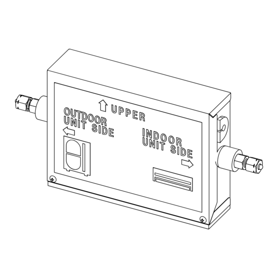
    Vor Ort zu beschaffende Teile Zubehörteile Anzahl RBM- Teilebezeichnung Form Verwendung PMV0361E PMV0901E Installationshandbuch Anschluss- und UPPER OUTDOOR INDOOR Übergangskabel Anschlusskabel für PMV-Steuerung UNIT SIDE UNIT SIDE (zum Anschluss an PMV-Kit) Zur Wärmeisolierung von Wärmeisolierung flüssigkeitsseitigen Rohrverbindungen Kabelbinder groß Zur Befestigung des PMV-Kits (Translation for type L) Kabelbinder mittel Zur Befestigung der Wärmeisolierung...
  • Seite 31 WARNUNG • Die Installation/Wartung der Klimaanlage nur von einem autorisierten Händler oder qualifizierten Techniker durchführen lassen. Eine unsachgemäße Installation kann zu Wasserleckage, elektrischen Schlägen oder Brandgefahr führen. • Vor Arbeiten an der Elektrik unbedingt den Netzhauptschalter (oder Trennschalter) in Ausschaltstellung bringen. Sicherstellen, dass sich alle Netzschalter in Ausgangsstellung befinden.
  • Seite 32: Installation Der Klimaanlage Für Neuen Kältemitteltyp

    INSTALLATION DER KLIMAANLAGE FÜR NEUEN KÄLTEMITTELTYP Dieses PMV-Kit arbeitet mit dem neuen HFC Kältemittel R410A. Dieses Kältemittel greift die Ozonschicht nicht an. • Das Kältemittel R410A wird durch Kontakt mit Wasser, Oxidationsmitteln oder Ölen beeinträchtigt, da das Kältemittel R410 mit einem 1.6-fach höheren Druck als das frühere Kältemittel verwendet wird. Durch die Umstellung auf das neue Kältemittel wurde auch das Kältemittelöl geändert.
  • Seite 33: Wahl Des Installationsorts

    WAHL DES INSTALLATIONSORTS VORSICHT Die Klimaanlage nicht an Orten installieren, an denen Leckage von brennbaren Gasen auftreten kann. Falls solche Gase im Umfeld der Klimaanlage austreten, entsteht Brandgefahr. Die Klimaanlage nach Absprache mit Kunden an einem Orten installieren, der die folgenden Bedingungen erfüllt.
  • Seite 34: Installationsraum

    Diese Kontrollöffnung ist für Installation und Service erforderlich. (Kontrollöffnung: 450 × 450 mm oder mehr) • Einen Abstand von 50 mm oder mehr zwischen Oberkante des Gehäuses und Decke vorsehen. • Die Anschlussrohrleitung zur Inneneinheit darf 2 bis 20 m lang sein. Platzbedarf RBM-PMV0361E, RBM-PMV0901E Gehäusedeckel 200 oder größer 200 oder größer Wartungsöffnung...
  • Seite 35: Installation Des Kältemittel-Umlaufsteuermoduls

    INSTALLATION DES PMV-KIT WARNUNG Die Anlage sicher an einem Ort installieren, der genugend Tragfestigkeit fur deren Gewicht bietet. Bei unzureichender Tragfestigkeit kann das Gerät durch Fall Personenschäden verursachen. Führen Sie eine spezielle Montage durch, um das Gerät gegen Erdbeben zu sichern. Unsachgemäße Installation kann zum Fall der Anlage führen.
  • Seite 36: Kältemittelleitung

    Schließen Sie die Kältemittelleitungen entsprechend der Markierungen an, nachdem Sie die Richtungen für Innen- und Außeneinheit überprüft haben. Rohrmaterial und Abmessungen Modellbezeichnung Kapazität der Inneneinheit Anschluss der Kältemittelleitung Hinweise RBM-PMV0361E Typ 007, 009, 012 Ø6.4 Typ 015, 018 Ø6.4 Anschlussstück Anschlussstück RBM-PMV0901E Typ 024 Ø9.5...
  • Seite 37: Anschluss Von Kältemittelleitungen

    Leitungsformung/Gewindeschneiden Anschluss von Kältemittelleitungen Alle Kältemittelleitungen mit Überwurfmuttern Bördeln anschließen • Beim Abnehmen der Überwurfmutter tritt das Füllgas 1. Die Leitung mit einem Rohrschneider (Stickstoff) aus dem Modul aus, was jedoch kein zurechtschneiden. Fehler ist. FALSCH • Für die Leitungsanschlüsse an der Inneneinheit unbedingt zwei Schlüssel verwenden.
  • Seite 38 KÄLTEMITTELLEITUNG Luftdichtigkeitstest/Entlüftung usw Für Luftdichtigkeitstests, Entlüften, Nachfüllen von Kältemittel und Gasleckprüfung die Anweisungen der Einbauanleitung für die Außeneinheit befolgen. ANFORDERUNGEN Nur spezielle Werkzeuge und Vorrichtungen wie Füllschläuche für das Kältemittel R410A verwenden. Keinesfalls die Anlage einschalten, bevor Luftdichtigkeitstest und Unterdruckaufbau abgeschlossen wurden. (Falls die Anlage vorzeitig eingeschaltet wird, schließt sich das integrierte PMV, was den Unterdruckaufbau erheblich verzögert.) Die Ventile an der Außeneinheit vollständig öffnen...
  • Seite 39: Befestigung Nach Anschluss Der Rohrleitungen

    BEFESTIGUNG NACH ANSCHLUSS DER ROHRLEITUNGEN 1. Befestigen Sie, nachdem Sie die Rohrleitungen angeschlossen haben, das PMV-Kit mit den beiliegenden Kabelbindern fest an die gasseitige Rohrleitung. Kabelbinder mitte L Kabelbinder mitte M Kabelbinder mitte M Kabelbinder mitte M Kabelbinder mitte L Kabelbinder mitte M Kältemittelleitung (Gasseite)
  • Seite 40: Elektrische Arbeiten

    ELEKTRISCHE ARBEITEN WARNUNG 1. Ausschließlich die angegebenen Kabeltypen für Anschlüsse verwenden und die Kabel sicher befestigen, so dass externe Krafteinwirkungen keine Zuglast auf die Anschlussklemmen bewirken. Unsachgemäße Anschlüsse oder unzureichende Festigkeit kann zu Bränden usw. führen. 2. Bei elektrischen Arbeiten unbedingt die örtlichen Vorschriften und Regeln sowie die Anweisungen der Einbauanleitung befolgen.
  • Seite 41 • Vorgehensweise 1 (bei Inneneinheiten, die kein Übergangskabel benötigen) 1) Schalten Sie die Stromversorgung der Inneneinheit ein und öffnen Sie das pulsmodulierte Ventil der Inneneinheit ganz. Schalten Sie die Stromversorgung der Inneneinheit nur dann ein, wenn die Stromversorgung der Außeneinheit abgeschaltet ist.
  • Seite 42: Einrichten Der Ausseneinheit

    ELEKTRISCHE ARBEITEN • Vorgehensweise 2 (bei Inneneinheiten, die ein Übergangskabel benötigen) Die Schritte 1) bis 3) entsprechen den in Vorgehensweise 1 beschriebenen Schritten. 4) Verbinden Sie das Übergangskabel mit dem Anschlusskabel (11 m) aus dem PMV-Kit. 5) Bei Auslieferung wurde der PMV-Anschluss der Inneneinheit an den Stecker CN32 auf der Leiterplatte der Inneneinheit angeschlossen.
  • Seite 43: Accessori E Pezzi Reperibili In Loco

    Accessori e pezzi reperibili in loco Accessori Q.tà RBM- Forma Utilizzo Nome delle parti PMV0361E PMV0901E Manuale di installazione Cavo di collegamentor Cavo UPPER di conversione del connettore OUTDOOR INDOOR Cavo di collegamento per controllo PMV UNIT SIDE UNIT SIDE (Collegato al Kit PMV) Tubo per isolamento da Per isolamento da riscaldamento della...
  • Seite 44 PRECAUZIONI DI SICUREZZA ATTENZIONE • Richiedere ad un rivenditore autorizzato o ad un tecnico professionista delle istallazioni qualificato di provvedere all’installazione/alla manutenzione del condizionatore d’aria. Un’installazione inadeguata può eventualmente causare perdite d’acqua, choc elettrici o incendi. • Disattivare l’interruttore dell’alimentazione elettrica generale o l’interruttore prima di effettuare qualsiasi operazione elettrica.
  • Seite 45: Installazione Del Condizionatore

    INSTALLAZIONE DEL CONDIZIONATORE D’ARIA CON IL NUOVO REFRIGERANTE Questo Kit PMV utilizza il nuovo refrigerante HFC (R410A) che non distrugge lo strato d’ozono. • Il fluido refrigerante R410A ha la tendenza ad essere interessato dalle impurità, come acqua, membrane ossidanti o oli perché...
  • Seite 46: Selezione Del Punto D'installazione

    SELEZIONE DEL PUNTO D’INSTALLAZIONE AVVERTENZA Non installare il condizionatore d’aria in un punto in cui si possano verificare perdite di gas combustibili. Se sono presenti perdite di gas che si raccolgano in prossimità del dispositivo, si possono eventualmente sviluppare incendi. Su approvazione del cliente, installare il condizionatore d’aria in una posizione che soddisfi le seguenti condizioni.
  • Seite 47: Spazio D'installazione

    • Mantenere un disimpegno di 50 mm o superiore tra il pannello superiore del dispositivo e il soffitto. • La lunghezza di un tubo di collegamento all’unità interna deve essere nel range da 2 m a 10 m. Spazio per l’installazione RBM-PMV0361E, RBM-PMV0901E Coperchio cassetta 200 o più...
  • Seite 48: Vista Esterna

    INSTALLAZIONE DEL KIT PMV ATTENZIONE Installare il dispositivo in maniera sicura in un punto in grado di offrire una resistenza sufficiente al peso del dispositivo. Se la base non è sufficiente solida, il dispositivo può eventualmente cadere provocando danni a persone. Eseguire un’operazione d’installazione specificata per proteggersi dai terremoti.
  • Seite 49: Condutture Del Refrigerante

    Materiale per tubature e dimensioni Nome del modello Tipo capacità unità interna Diametro del tubo del refrigerante Note RBM-PMV0361E Tipo 007, 009, 012 Ø6.4 Tipo 015, 018 Ø6.4 RBM-PMV0901E Tipo 024 Ø9.5...
  • Seite 50 CONDUTTURE DEL REFRIGERANTE Profilatura dei tubi/Disposizione finale Collegamento del tubo del fluido refrigerante Svasatura Collegare tutti i tubi del fluido refrigerante con le connessioni svasate. 1. Tagliare il tubo con un tagliatubi. • Dato che solo la pressione atmosferica viene sigillata sottoforma di gas sigillante, non è...
  • Seite 51 Collaudo della tenuta stagna/Depolverazione con ricambio d’aria, ecc. Per il collaudo della tenuta stagna, depolverazione con ricambio d’aria, aggiunta di fluido refrigerante e verifica delle perdite di gas, attenersi al manuale d’installazione allegato al dispositivo esterno. REQUISITI Accertarsi di utilizzare la strumentazione adeguata, quale il manicotto di carico specifico per R410A. Non attivare l’alimentazione fino a quando non saranno completati il collaudo della tenuta stagna e la chiusura sottovuoto.
  • Seite 52: Come Fissare Dopo Il Collegamento Dei Tubi

    COME FISSARE DOPO IL COLLEGAMENTO DEI TUBI 1. Dopo il collegamento dei tubi, fissare il Kit PMV Kusando la fascetta di legatura trattenendola vicina al tubo del gas. Fascetta di legatura L Fascetta di legatura M Fascetta di legatura M Fascetta di legatura M Fascetta di legatura L Fascetta di legatura M...
  • Seite 53: Impianto Elettrico

    IMPIANTO ELETTRICO ATTENZIONE 1. Utilizzando i cavi specificati, accertarsi di collegare i cavi e fissare gli stessi in modo sicuro per evitare che la robustezza esterna dei cavi non si trasferisca al componente di collegamento dei terminali. Un collegamento o un fissaggio incompleti potrebbe provocare incendi, ecc. 2.
  • Seite 54 IMPIANTO ELETTRICO • Procedura di lavoro 1 (In caso di Unità interna in cui il cavo di conversione del connettore non è usato) 1) Accendere solo l’alimentazione elettrica dell’unità interna e aprire completamente la valvola del servomotore a impulsi incorporata nell’unità interna. Accendere l’alimentazione elettrica dell’unità...
  • Seite 55: Impostazione Iniziale Dell'unità Esterna

    • Procedura di lavoro 2 (In caso di Unità interna in cui il cavo di conversione del connettore è usato) I punti da 1) a 3) sono identici a quelli spiegati per la procedura 1. 4) Giuntare e aggiungere il cavo di conversione del connettore al cavo di collegamento (11m) che è fuori della dalla cassetta del Kit PMV.
  • Seite 56: Accesorios Y Piezas Que Se Obtienen Por Separado

    Accesorios y piezas que se obtienen por separado Accesorios Cantidad RBM- Nombre del componente Forma Utilización PMV0361E PMV0901E Manual de instalación Cable de conexión y cable UPPER OUTDOOR INDOOR de conversión del conector Cable de conexión para el control PMV UNIT SIDE UNIT SIDE (conectado al Juego PMV)
  • Seite 57 ADVERTENCIA • Póngase en manos de un vendedor autorizado o de un profesional cualificado para que se ocupen de la instalación y el mantenimiento del aparato del aire acondicionado. Una instalación incorrecta podría ocasionar pérdidas de agua, cortocircuitos o incendios. •...
  • Seite 58: Instalación Del Nuevo Aparato De Aire Acondicionado Refrigerante

    INSTALACIÓN DEL NUEVO APARATO DE AIRE ACONDICIONADO REFRIGERANTE Este Juego de PMV utiliza el nuevo refrigerante HFC (R410A) que no daña la capa de ozono. • Al refrigerante R410A le pueden afectar impurezas como el agua, la membrana de oxidación o aceites, ya que la presión del refrigerante R410A es unas 1.6 veces superior a la del refrigerante anterior.
  • Seite 59: Selección Del Lugar De Instalación

    SELECCIÓN DEL LUGAR DE INSTALACIÓN PRECAUCIÓN No instale el aparato de aire acondicionado en un lugar donde puedan producirse escapes de gas combustible. Si hay un escape de gas alrededor del aparato, pueden provocarse incendios. Con el consentimiento del cliente, instale el aparato de aire acondicionado en un lugar que cumpla las siguientes condiciones.
  • Seite 60: Espacio De Instalación

    • Guarde al menos 50 mm. entre el panel superior de la unidad y el techo. • La longitud de un tubo de conexión a la unidad interior debe ser de 2 m a 10 m. Espacio de instalación RBM-PMV0361E, RBM-PMV0901E Tapa de la caja 200 o más 200 o más...

Diese Anleitung auch für:

Rbm-pmv0901e

Inhaltsverzeichnis