Werbung
Quicklinks
HARTING Electronics GmbH
P.O. Box 14 73 | D-32339 Espelkamp
HARTING.electronics@HARTING.com
Wanddurchführung · Panel feed-through · Traversée
PushPull signal
Bestell-Nummer · Part number · Réf. article
09 45 545 9010
www.HARTING.com
Montageanleitung
Assembly instruction
Instructions d'assemblage
1. Zubehör · Accessories · Accessoires
Anbaugehäuse:
Bulkhead mount housing:
Boîtier de montage:
• H ARTING PushPull Var. 4
EasyInstall Kunststoff · Plastic · Plastique
Compact Kunststoff · Plastic · Plastique
• H an
PushPull Var. 14
®
Kunststoff · Plastic · Plastique
Metall rechteckig · Metal rectangular · Métal rectangulaire
Metall rund · Metal circular · Métal circulaire
D-Sub Crimpkontakte:
D-Sub crimp contacts:
Contacts sertis subminiatures :
Stiftkontakte für Wanddurchführung
Male contacts for panel feed-through
Contacts mâles pour traversée
für/for/pour AWG 24-20; 0,25-0,56 mm
für/for/pour AWG 22-18; 0,33-0,82 mm
Werkzeuge für D-Sub Crimpkontakte:
Deutsch
Tools for D-Sub crimp contacts:
Outils pour contacts sertis subminiatures :
E
nglish
Français
Zur Verarbeitung mit Crimpzange 09 99 000 0175
1)
1)
For processing with crimping tool 09 99 000 0175
Mise en œuvre avec pince à sertir 09 99 000 0175
1)
2)
Zur Verarbeitung mit Crimpzange 09 99 000 0501.
Passende Positionshülse: 61 03 600 0531
For processing with crimping tool 09 99 000 0501.
2)
Matching locator: 61 03 600 0531
Mise en œuvre avec pince à sertir 09 99 000 0501.
2)
Douille de positionnement correspondante : 61 03 600 0531
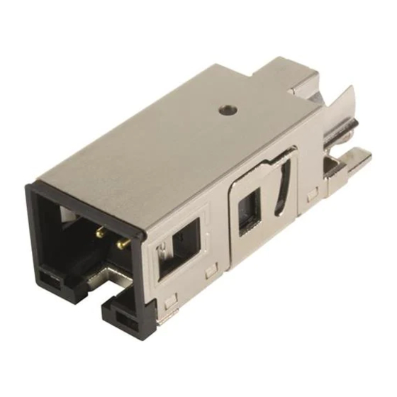
2. Aufbau · Configuration · Configuration
Abb. / Fig. / Fig. 1: Wanddurchführung Metall
09 45 545 0032
09 45 545 0028
09 35 012 0331
Abb. / Fig. / Fig. 2: Wanddurchführung Kunststoff
09 35 012 0311
09 35 012 0312
1 PushPull Anbaurahmen Metall / Kunststoff · PushPull bulkhead
frame metal / plastic · Cadre support Push Pull en métal / plastique
2 Flachdichtung · Flat seal · Joint plat
3 Kunststoff-Adapter für Metall-Anbaurahmen · Plastic adapter
for bulkhead frame metal · Adaptateur en plastique pour cadre
support en métal
4 Kontakteinsatz Unterteil · Contact insert, lower part · Insert de
contact, partie du bas
5 Schirmblech für Kontakteinsatz · Shielding plate for contact
insert · Tôle de blindage pour insert de contact
2
09 67 000 8178
1)
6 Kabelbinder zur Zugentlastung (optional) · Strain relief via
cable tie (optional) · Collier de serrage servant de décharge de
2
09 67 000 3576
2)
traction (en option)
Panel feed-through metal · Traversée métal
Panel feed-through plastic · Traversée plastique
3. Konfektionierung · Assembly · Câblage
Abb. / Fig. / Fig. 3
X
geschirmt · shielded · blindé
ungeschirmt · unshielded · non-blindé
22 - 24
• E ntfernen Sie den Kabelmantel auf einer Länge von 27-29 mm und die
Einzelisolierung auf einer Länge von 4 mm (Abb. 3).
• K lappen Sie das Schirmgeflecht über den Kabelmantel zurück. Entfer-
nen Sie ggf. vorhandene Schirm- und Schutzfolien.
• C rimpen Sie mit geeignetem Werkzeug die Stiftkontakte auf die abiso-
lierten Einzeladern (Abb. 4).
• Remove the cable jacket at a length of 27-29 mm and the individual
insulation at a length of 4 mm (Fig. 3).
• Fold the shield braid back over the cable jacket. Remove any
existing shielding foil and protective foil.
• Using an appropriate tool, crimp the male contacts on to the
stripped single strands (Fig. 4).
• Retirer la gaine du câble sur une longueur de 27-29 mm et dénuder l'iso-
lation individuelle sur une longueur de 4 mm (Fig. 3).
• Rabattre la tresse de blindage sur la gaine du câble. Si nécessaire, reti-
rer les films de blindage et de protection.
• A l'aide d'un outil adapté, sertir les contacts sur chaque fil dont l'isola-
tion a été retirée (Fig. 4).
Abb. / Fig. / Fig. 4
• O rdnen Sie die Einzeladern gemäß der gewünschten Belegung.
• F ühren Sie die einzelnen Adern in die Kammern des Isolierkörper ein.
Anschließend schwenken Sie die Isolierkörper in das Metall-Grundge-
häuse ein, bis es mit einem hörbaren Klick verrastet. (Abb. 5).
• S etzen Sie anschließend das Schirmblech auf den Isolierkörper und
das Grundgehäuse, bis es ebenfalls hörbar verrastet (Abb. 6+7).
25 - 27
Werbung

Verwandte Anleitungen für HARTING 09 45 545 9010


Inhaltszusammenfassung für HARTING 09 45 545 9010
- Seite 1 Abb. / Fig. / Fig. 3 Bestell-Nummer · Part number · Réf. article Passende Positionshülse: 61 03 600 0531 09 45 545 9010 For processing with crimping tool 09 99 000 0501. Matching locator: 61 03 600 0531 geschirmt · shielded · blindé...
- Seite 2 2012-10 Irrtum und technische Änderungen vorbehalten. Instruction number: 09 45 545 9010/99.00 2012-10 Errors and technical changes excepted. No. instructions d’assemblage: 09 45 545 9010/99.00 2012-10 Abb. / Fig. / Fig. 8 Abb. / Fig. / Fig. 9 Abb. / Fig. / Fig. 14...