Pilz PNOZ mi2p Betriebsanleitung
Quicklinks
21135-01
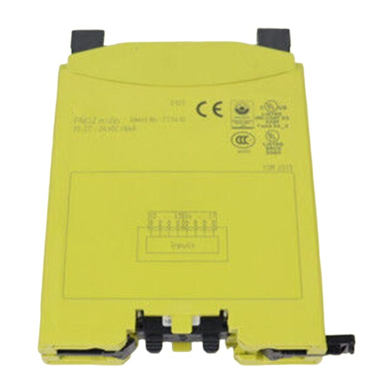
PNOZ mi2p
4
D
Betriebsanleitung
4
GB Operating instructions
4
F
Manuel d`utilisation
Das Erweiterungsmodul PNOZ mi2p
Das Erweiterungsmodul PNOZ mi2p darf nur
an ein Basisgerät (z. B. PNOZ m1p des
modularen Sicherheitssystems PNOZmulti)
angeschlossen werden. Das modulare
Sicherheitssystem PNOZmulti dient dem
sicherheitsgerichteten Unterbrechen von
Sicherheitsstromkreisen und ist bestimmt für
den Einsatz in:
• NOT-AUS-Einrichtungen
• Sicherheitsstromkreisen nach VDE 0113
Teil 1, 11/98 und EN 60204-1, 12/97
(z. B. bei beweglichen Verdeckungen)
Achtung!
Das PNOZ m2p hat Eingänge für
Standardfunktionen. Sie dürfen nicht
für sicherheitsgerichtete Funktionen
verwendet werden.
Lieferumfang:
• Erweiterungsmodul PNOZ mi2p
• Steckbrücke: 774 639
Zu Ihrer Sicherheit
Das Erweiterungsmodul PNOZ mi2p erfüllt
alle notwendigen Bedingungen für einen
zuverlässigen Betrieb.
Beachten Sie jedoch nachfolgend aufge-
führte Sicherheitsbestimmungen:
• Installieren und nehmen Sie das Modul nur
dann in Betrieb, wenn Sie mit dieser
Betriebsanleitung und den geltenden
Vorschriften über Arbeitssicherheit und
Unfallverhütung vertraut sind.
• Verwenden Sie das Modul nur gemäß
seiner Bestimmung. Beachten Sie dazu
auch die Werte im Abschnitt "Technische
Daten".
• Halten Sie beim Transport, bei der
Lagerung und im Betrieb die Bedingungen
nach EN 60068-2-6, 01/00 ein (siehe
"Technische Daten").
• Öffnen Sie nicht das Gehäuse und
nehmen Sie auch keine eigenmächtigen
Umbauten vor.
• Schalten Sie bei Wartungsarbeiten (z. B.
beim Austausch von Schützen) unbedingt
die Versorgungsspannung ab.
Beachten Sie unbedingt die Warnhinweise in
den anderen Abschnitten dieser Anleitung.
Diese Hinweise sind optisch durch Symbole
hervorgehoben.
Wichtig: Beachten Sie die Sicher-
heitsbestimmungen, sonst erlischt
jegliche Gewährleistung.
Modulbeschreibung
Modulmerkmale:
• 8 Eingänge
• konfigurierbar mit PNOZmulti Configurator
• max. 8 Erweiterungsmodule an das
Basisgerät PNOZ m1p anschließbar
4
E
Instrucciones de uso
4
I
Istruzioni per l`uso
4
NL Gebruiksaanwijzing
The PNOZ mi2p expansion module
The PNOZ mi2p expansion module may only
be connected to a base unit (e.g.
PNOZ m1p from the PNOZmulti modular
safety system). The PNOZmulti modular
safety system is used for the safety-related
interruption of safety circuits and is designed
for use in:
• Emergency stop equipment
• Safety circuits in accordance with
VDE 0113 Part 1, 11/98 and EN 60204-1,
12/97 (e.g. on movable guards)
Caution!
The PNOZ m2p has inputs for
standard functions. They may not be
used for safety-related functions.
Range:
• Expansion module PNOZ mi2p
• Link: 774 639
For your safety
The PNOZ mi2p expansion module meets all
the necessary conditions for reliable
operation.
However, always ensure the following safety
requirements are met:
• Only install and commission the module if
you are familiar with both these instructions
and the current regulations for health and
safety at work and accident prevention.
• Only use the module in accordance with its
intended purpose. Please also take note of
the values in the "Technical details"
section.
• Transport, storage and operating condi-
tions should all conform to EN 60068-2-6,
01/00 (see "Technical details").
• Do not open the housing or undertake any
unauthorised modifications.
• Please make sure you shut down the
supply voltage when performing mainte-
nance work (e.g. replacing contactors).
You must take note of the warnings given in
other sections of these operating instructions.
These are highlighted visually through the
use of symbols.
Notice: Failure to keep to these safety
regulations will render the warranty
invalid.
Module description
Module features:
• 8 inputs
• Can be configured using the PNOZmulti
Configurator
• Max. of 8 expansion modules can be
- 1 -
Le module d'extension PNOZ mi2p
Le module d'extension PNOZ mi2p ne doit
être raccordé qu'à un appareil de base (par
exemple PNOZ m1p du système de sécurité
modulaire PNOZmulti). Le système de
sécurité modulaire PNOZmulti est conçu
pour interrompre en toute sécurité des
circuits de sécurité. Il est conçu pour être
utilisé dans les :
• circuits d'arrêt d'urgence
• circuits de sécurité selon les normes VDE
0113-1, 11/98 et EN 60204-1, 12/97
(p. ex. pour protections mobiles)
Attention !
Le PNOZ m2p possède des entrées
pour les fonctions standard. Elles ne
doivent pas être utilisées pour des
fonctions de sécurité.
Contenu de la livraison :
• module d'extension PNOZ mi2p
• cavalier de pontage: 774 639
Pour votre sécurité
Le module d'extension PNOZ mi2p satisfait
à toutes les conditions nécessaires pour un
fonctionnement sûr.
Toutefois, vous êtes tenu de respecter les
prescriptions de sécurité suivantes :
• Vous n'installerez le module et ne le
mettrez en service qu'après vous être
familiarisé avec le présent manuel
d'utilisation et les prescriptions en vigueur
sur la sécurité du travail et la prévention
des accidents.
• N'utilisez le module que conformément à
l'usage auquel il est destiné. À ce sujet,
respectez les valeurs indiquées à la
section "Caractéristiques techniques".
• Pour le transport, le stockage et l'utilisa-
tion, respectez les exigences de la norme
EN 60068-2-6, 01/00 (voir "Caractéristi-
ques techniques").
• N'ouvrez pas le boîtier et n'effectuez pas
de modifications non autorisées.
• En cas de travaux de maintenance (p.
ex. remplacement des contacteurs),
coupez impérativement la tension
d'alimentation.
Respectez impérativement les avertis-
sements dans les autres paragraphes du
présent manuel d'utilisation. Ces avertisse-
ments sont signalés par des symboles
visuels.
Important : respectez les consignes
de sécurité sinon la garantie devient
caduque.
Description du module
Caractéristique du module :
• 8 entrées
• Paramétrable avec PNOZmulti Configurator
• Possibilité de raccorder jusqu'à 8 modules
d'extension maximum à l'appareil de base

Verwandte Anleitungen für Pilz PNOZ mi2p


Inhaltszusammenfassung für Pilz PNOZ mi2p
- Seite 1 The PNOZ mi2p expansion module Le module d’extension PNOZ mi2p Das Erweiterungsmodul PNOZ mi2p darf nur The PNOZ mi2p expansion module may only Le module d’extension PNOZ mi2p ne doit an ein Basisgerät (z. B. PNOZ m1p des be connected to a base unit (e.g.
- Seite 2 • Statusanzeigen connected to the PNOZ m1p base unit PNOZ m1p • steckbare Klemmen, wahlweise mit • Status indicators • Affichages d’état Käfigzugfederanschluss oder • Plug-in terminals, either with cage clamp • Bornes enfichables, au choix avec con- Schraubanschluss connection or screw connection nexion par ressort type cage ou par vis Funktionsbeschreibung Function description...
- Seite 3 Hilfe der Rastelemente auf der Rückseite springs on the safety system are pressed • Montez le système de sécurité sur un rail auf einer Normschiene. Führen Sie das on to the DIN rail. DIN à l’aide du système de fixation situé Sicherheitssystem gerade auf die Norm- •...
- Seite 4 Betriebsbereitschaft herstellen: Preparing the unit for operation: Mise en route : Die Belegung der Eingänge wird im The input assignment is defined in the L’affectation des entrées est déterminée avec PNOZmulti Configurator festgelegt. PNOZmulti Configurator. le PNOZmulti Configurator. • Verdrahten Sie den Eingangskreis wie in •...
- Seite 5 Technische Daten Technical details Caractéristiques techniques Elektrische Daten Electrical data Données électriques Versorgungsspannung (U Supply voltage (U Tension d’alimentation (U über Basisgerät/via base unit/par l’appareil de base Leistungsaufnahme bei U Power consumption at U Plage de la tension d'alimentation (U <...
- Seite 6 Modulo di espansione PNOZ mi2p De uitbreidingsmodule PNOZ mi2p El módulo de ampliación PNOZ m2p puede Il modulo di espansione PNOZ mi2p può De uitbreidingsmodule PNOZ mi2p mag ser conectado sólo en un dispositivo básico essere collegato soltanto ad un dispositivo di alleen op een basismodule (b.v.
- Seite 7 • Indicaciones de estado • Morsetti inseribili, a scelta con collegamen- • Status-LED’s • Bornes insertables, opcionalmente con to a molla di trazione a gabbia o collega- • Steekbare klemmen, naar keuze met veer- conexión por resorte o de tornillo mento a vite of schroefaansluiting Descripción del funcionamiento...
- Seite 8 • Fijar el sistema de seguridad a una guía Posizioni di montaggio differenti possono • Bevestig het veiligheidssysteem op een normalizada con ayuda de los elementos provocare danni irreparabili al dispositivo DIN-rail met behulp van de relaisvoet op de encaje en la parte trasera. Colocar el di sicurezza.
-
Seite 9: Funzionamento
Puesta en marcha del sistema de Messa in funzione del sistema di Veiligheidssysteem in gebruik nemen Ingebruikneming voorbereiden: seguridad sicurezza Neem bij de voorbereiding van de ingebruik- Preparación de la puesta en marcha: Preparazione della messa in funzione: neming de volgende zaken in acht: Al preparar la puesta en marcha hay que Durante la preparazione della messa in •... - Seite 10 Datos técnicos Dati tecnici Technische gegevens Características eléctricas Dati elettrici Elektrische gegevens Tensión de alimentación (U Tensione di alimentazione (U Voedingsspanning (U a través del dispositivo básico/mediante dispositivo di base/via basismodule Consumo de energía con U Potenza assorbita a U Opgenomen vermogen bij U <...
- Seite 11 D D D D D F F F F F Anschlussbeispiel: Connection example: Exemple de raccordement : PNOZ mi2p: Abfrage von SPS- Aus- PNOZ mi2p: Querying of PLC PNOZ mi2p : Interrogation des gängen (Standardfunktion) outputs (standard function) sorties API (fonction standard)
- Seite 12 0224 2360180, Fax: 0224 2360184, E-Mail: pilz.tr@pilz.de Pilz Automation Safety L.P ., 734 354-0272, Fax: 734 354-3355, E-Mail: info@pilzusa.com www.pilz.com ✆ Pilz GmbH & Co. KG, Sichere Automation, Felix-Wankel-Straße 2, 73760 Ostfildern, Deutschland, +49 711 3409-0, Fax: +49 711 3409-133, E-Mail: pilz.gmbh@pilz.de - 12 -...