Herunterladen Inhalt Inhalt Diese Seite drucken

Werbung

Verfügbare Sprachen

Verfügbare Sprachen

Benutzerhandbuch / User's Manual
UPSI-2401
USV-Systeme
Industrie-PC-Netzteile
Netzteile
Medizintechnik
DC/DC-Wandler
USV-Systeme
Systemkomponenten

Werbung

Inhaltsverzeichnis
loading

Inhaltszusammenfassung für Bicker UPSI-2401

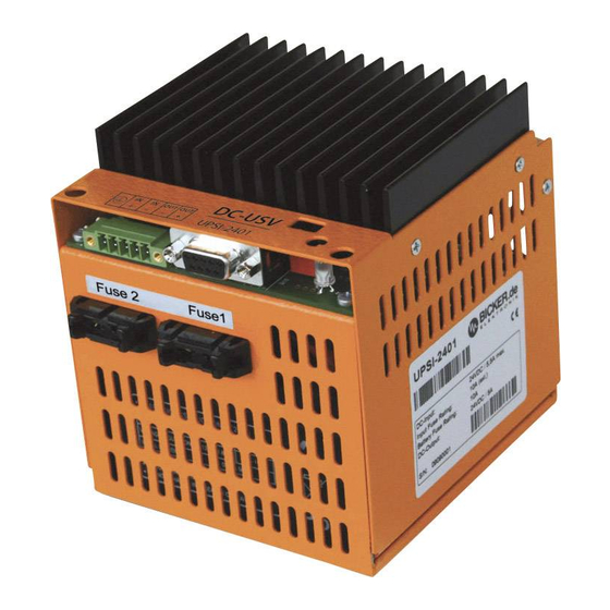
  • Seite 1 USV-Systeme Benutzerhandbuch / User’s Manual UPSI-2401 Industrie-PC-Netzteile Netzteile Medizintechnik DC/DC-Wandler USV-Systeme Systemkomponenten...
  • Seite 2: Inhaltsverzeichnis

    Benutzerhandbuch UPSI-2401 Allgemeines und Hinweise ........5 1.1 Lieferumfang ....................5 1.2 Optional erhältliches Zubehör .............. 5 Technische Daten ............. 6 Funktionsprinzip ............8 3.1 Netz-Betrieb ...................... 8 3.2 Batterie-Betrieb ....................8 LED-Anzeige ............... 9 Montage und Inbetriebnahme ......10 5.1 DC-Stecker ...................... 11 5.2 Schnittstelle 9-polig Sub-D ..............11 5.3 RUPS2000-B1 (USV-Management-Software) ......12 5.4...
  • Seite 3: Ihre Vorteile Auf Einen Blick

    Dieses Handbuch soll Sie mit den Komponenten und Eigenschaften der DC-USV Ihre Vorteile auf einen Blick UPSI-2401 vertraut machen. Wir haben alle Sorgfalt walten lassen, um in diesem Handbuch vollständige und genaue Informationen über unser Produkt zu liefern. Für Kontinuierliche Überwachung der Batteriekapazität möglicherweise vorhandene Fehler kann jedoch keine Haftung übernommen werden.
  • Seite 4: Technische Daten

    Benutzerhandbuch UPSI-2401 Benutzerhandbuch UPSI-2401 2 Technische Daten der DC-USV UPSI-2401 Zeichnung UPSI-2401 T e c h n i s c h e D a t e n 100,0 mm Eingangsspannung 24 V DC (22,5…30 V) Montageplatte 80,0 mm F1-0162, Eingangsstrom 5,5 A max. optionales Zubehör Ausgangsspannung Im Normalbetr.: ca. 0,5 V unterhalb Eingangsspannung...
  • Seite 5: Funktionsprinzip

    3.1 Netz-Betrieb Im Netz-Betrieb liefert eine vorgeschaltete Spannungsquelle 24 V DC. Diese Spannung Kurzschluss am Ausgang abzüglich ca. 0,45 V DC liegt direkt am Verbraucher (z. B. PC) an. Der interne Batteriepack wird von der UPSI-2401 geladen. Die LED leuchtet grün und die Schnittstelle signali- Kurzschluss bzw. Überlast am Ausgang beseitigen. siert „Power ok“. Etwa alle 10 Minuten wird ein Batterietest durchgeführt. Bei defektem USV kann durch Netztrennung wieder neu gestartet werden. Batteriepack oder Leitungsbruch blinkt die LED rot/grün. LED-Anzeigen bei Umschaltung in den USV-Betrieb und Absenkung der 3.2 Batterie-Betrieb...
  • Seite 6: Montage Und Inbetriebnahme

    Benutzerhandbuch UPSI-2401 Benutzerhandbuch UPSI-2401 5 Montage und Inbetriebnahme 5.1 DC-Stecker: Anschluss Ein- und Ausgang Typ: FRONT-MC1,5/5-STF-3,81 Anschlussbild PIN DC-Stecker Interface Stecker 2: DSUB9 1 Erde 1 Erde Interface für RUPS2000 – – 2 Eingang (+) 1 Battery low Ausgang 2 Eingang (+) Die Ausgangsspannung folgt der angeschlos- 3 Eingang (–)
  • Seite 7: Rups2000-B1 (Usv-Management-Software)

    2003, XP, Vista 7 und 8 (andere OS auf Anfrage). Die Open Kollektorschnittstelle des Kehrt während eines Netzausfalls und der schon eingeleiteten Shutdown-Phase von DC-USV-Moduls UPSI-2401 ist für die Software RUPS 2000-B1 konzipiert. Diesem Windows® das Netz wieder zurück, so „hängt“ das Betriebssystem mit der Meldung: Softwarepaket liegt optional das CB-RS-020 Schnittstellen-Kabel bei. Damit kann die...
  • Seite 8: Fehlerbehebung

    Battery fail (Batterie defekt) Die LED blinkt rot/grün, wenn der interne Batteriepack tief entladen oder defekt ist. Technical Data............18 die Batteriezuleitung oder Sicherung defekt ist. Weitere Anzeige-Schemen siehe Seite 9. Functional Description .......... 20 3.1 Mains Mode ....................20 Die UPSI-2401 schaltet in Verbindung mit RUPS 2000-B1 nicht ab. Das Häkchen unter „Settings“, „Shutdown“ und „USV abschalten“ 3.2 Battery Mode ....................20 wurde nicht gesetzt. Die Shutdown-Unterdrückungszeit (Punkt 5.4) wurde nicht abgewartet, und somit wurde der Shutdown-Impuls „unterdrückt“. LED Display ............... 21 Das Schnittstellenkabel ist defekt oder ein falsches Schnittstellenkabel wurde verwendet.
  • Seite 9: General Information And Safety Warnings

    User’s Manual UPSI-2401 User’s Manual UPSI-2401 1 General Information and Safety Warnings Congratulations for choosing the UPSI-2401! This manual explains the components and properties of the DC UPS UPSI-2401. All infor- Your advantages at a glance mation contained in this manual has been revised thoroughly to ensure accuracy and completeness. Yet Bicker Electronic accepts no liability for any omissions or faults. We will Continuous monitoring of battery capacitance appreciate any notifications regarding faults, suggestions for improvements and criticism. Temperature-regulated and gentle charging of battery Comfortable switch-off via timer function also possible Sa fe ty W a rni ng s Installation and connection must only be carried out by qualified personnel.
  • Seite 10: Technical Data

    User’s Manual UPSI-2401 User’s Manual UPSI-2401 2 Technical Data of the DC-UPS UPSI-2401 Drawing UPSI-2401 T e c h n i c a l d a t a 100,0 mm Mounting plate Input voltage 24 V DC (22.5…30 V) 80,0 mm F1-0162, Input current 5.5 A max.
  • Seite 11: Functional Description

    User’s Manual UPSI-2401 User’s Manual UPSI-2401 3 Functional Description 4 LED Display Power ok In case of a mains voltage failure the DC UPS UPSI-2401 supplies the connected consumer load with DC voltage from the internal battery pack. Via LED display the status The LED is green as long as an input voltage (>20 V DC) is present. is visualised. Signals can be informed to a connected PC via interface. Power fail (mains power failure) The LED turns to orange as soon as the DC UPS UPSI-2401 switches Source: e. g. AC/DC power supply to battery mode (input voltage <20 V DC).
  • Seite 12: Installation And Start Up

    User’s Manual UPSI-2401 User’s Manual UPSI-2401 5 Installation and Start up 5.1 DC Connector: Input and output connection Type: FRONT-MC1,5/5-STF-3,81 Connections DC connector 1 Interface connector 2: 1 Earth – – DSUB9 Interface für 1  Earth 2 Input (+) RUPS2000 2  Input (+) The output voltage corresponds to the connected input 3 ...
  • Seite 13: Rups2000-B1 (Ups Management Software)

    DC UPS UPSI-2401 has been designed for the software RUPS 2000-B1. system will ‘lock’ with the message “Your PC is now safe”. The reboot function restarts the Optionally the interface cable CB-RS-020 is included into the delivery of this software system after about 5 seconds. package. With this cable the UPSI-2401 can be connected to a free COM-Port of a No intervention of the user is required. connected PC. Shutdown Suppression...
  • Seite 14: Troubleshooting

    PC System crash during UPS mode Connection interrupted or defect fuse on battery side Connected load <10 W (load sensor) Battery pack has not enough capacitance or is discharged Battery fail (Battery defect) The LED flashes red/green when the internal battery pack is discharged or defect. when the battery supply line or fuse is defect. For further display schemes please have look at page 21. The UPSI-2401 does not switch off in connection with RUPS 2000-B1. The checkmark under “Settings“, “Shutdown“ and “Switch off UPS“ (USV abschalten) was not set. The shutdown suppression period (see 5.4) was disturbed, and the shutdown impulse was, thus, “suppressed“. The interface cable is defect or a wrong interface cable was used. Battery is not fully charged Battery pack defect No function Polarity reversal of input voltage? >> internal fuse defect...
  • Seite 15 Industrial PC PSUs Power supplies Medical applications DC/DC converters UPS systems System components Bicker Elektronik GmbH Ludwig-Auer Straße 23 86609 Donauwörth · Germany Tel. +49 (0)906 70595-0 Irrtümer und technische Änderungen vorbehalten.  Fax +49 (0)906 70595-55 Windows® ist ein eingetragenes Warenzeichen der Firma Microsoft Corp.    E-Mail: info@bicker.de Subject to errors and technical modifications.  Windows® is a registered trademark of Microsoft Corporation.    www.bicker.de Stand/Issued: 03.06.2014...

Inhaltsverzeichnis