Leb electronics AL400AC Anleitungen Und Hinweise Für Installation, Gebrauch Und Wartung
Elektromechanisches getriebe für flügeltore
Inhaltsverzeichnis
Verfügbare Sprachen
Verfügbare Sprachen
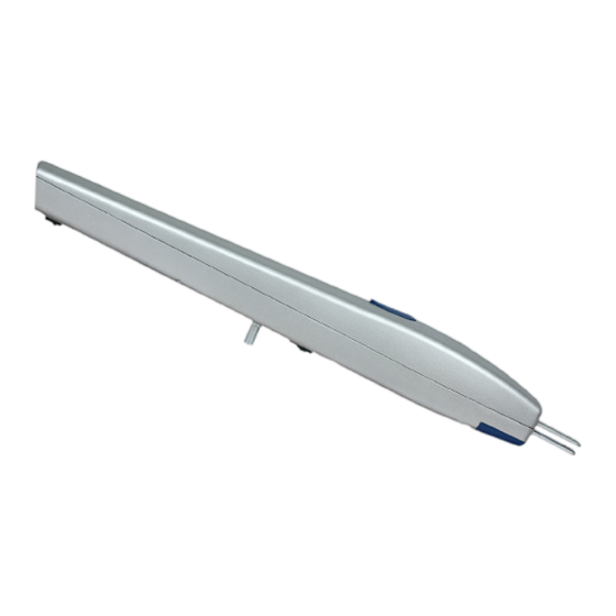
Attuatore lineare elettromeccanico per cancelli a battente
Linear electromechanical operator for wing gates
Opérateur linéaire électromécanique pour portails battants
Elektromechanisches getriebe für flügeltore
Istruzioni e avvertenze per l'installazione, l'uso e la manutenzione
Instructions and warnings for installation, use and maintenance
Instructions et avertissements pour l'installation, l'usage et l'entretien
Anleitungen und hinweise für installation, gebrauch und wartung
ARROW
Inhaltsverzeichnis

Inhaltszusammenfassung für Leb electronics AL400AC
- Seite 1 ARROW Attuatore lineare elettromeccanico per cancelli a battente Linear electromechanical operator for wing gates Opérateur linéaire électromécanique pour portails battants Elektromechanisches getriebe für flügeltore Istruzioni e avvertenze per l’installazione, l’uso e la manutenzione Instructions and warnings for installation, use and maintenance Instructions et avertissements pour l'installation, l'usage et l'entretien Anleitungen und hinweise für installation, gebrauch und wartung...
- Seite 26 DEUTSCHE Warnungen - Dieses Handbuch ist nur technischem Fachpersonal und nicht dem Endverwerter bestimmt. Der Installateur muss später den Verwerter über den Automatismusverbrauch und die möglichen Gefahren sowie über die Notwendigkeit einer regelmäßigen Instandhaltung unterrichten. - Die Installation muss nur bei Fachpersonal, das die notwendigen technischen und beruflichen Fähigkeiten hat, ausgeführt werden.
-
Seite 27: Technische Verzeichnisse
DEUTSCHE TECHNISCHE VERZEICHNISSE AL400AC AL400DC TECHNISCHE DATEN (ARROW 230) (ARROW 24) Speisungsspannung 230 Vac - 50 Hz 24 Vdc Absorption 3,2 A Kraft 50 W 40 W Kondensator 6 uF Höhste Ständerlauf 400 mm 400 mm Antrieb 2400 N 2000 N Thermoschutz 120 °C... - Seite 28 DEUTSCHE INSTALLATION Vorprufüngen Bevor der Installation von ARROW vorangehen, sichern Sie Sich über die folgenden Punkte: - Sichern Sie Sich, dass die Vorrichtung innerhalb seine aus der folgende Tabelle gewinnbaren Gebrauchgrenze arbeitet: Gewicht der Tür (Kg) Länge der Tür (m) - Sichern Sie Sich, dass der Türaufbau fest ist und, dass dieselbe ohne Reibungen oder anderen Verhinderungen lauft.
- Seite 29 DEUTSCHE -Bevor die Bügel, zu befestigen, sichern Sie Sich, dass die Zahl “C” auf dem Stützeaufbau nicht mehr als die in der Montagetabelle berichten Wert ist. In der folgenden Montagetabelle werden die Bezugzahlen für die Installation der Anlasser berichten. ÖFFNUNG A (mm) B (mm) C (mm)
-
Seite 30: Hinterbügelpositionierung
ITALIANO DEUTSCHE Hinterbügelpositionierung - Bestimmen Sie die Befestigungsstelle der Hinterbügels nach der Beachtung der auf der Montagetabelle berichteten Zahlen “A”, “B” “C”. - Befestigen Sie den Bügel durch geeignete Ausdehnungseinsatzstücke (wenn der Pfeiler ein Mauerwerk ist) Vorderbügelpositionierung - Führen Sie den Türflügel bis die durch die mechanische Haltevorrichtung abgegrenzte Vollschließungsstelle. -
Seite 31: Anlasserpositionierung
DEUTSCHE - Heben Sie den Schutzdeckel des Schlosses (Abb. 2). - Stecken Sie den Schlüssel im Schloss und kreisen ihn in Rechtdrehung 90°, jetzt ist der Flügel frei und kann handlich verschieben werden (Abb. 3). - Um wieder den Flügel, anzuhängen, stecken Sie den Schlüssel und recht drehen Sie ihn 90°. -
Seite 32: Elektrische Verbindungen
DEUTSCHE ITALIANO - Stecken Sie die Gabel des Anlassers auf dem Hinterbügel, und machen Sie die Löcher, wie in der Abbildung 5 illustriert übereinstimmen. - Befestigen Sie die Gabel dem Hinterbügel durch die in Ausrüstung gelieferte Schrauben, Scheibe und selbstsperrenden Würfel. - Befestigen Sie den Anlasser dem Vorderbügel durch die in Ausrüstung gelieferten Schraub und Scheibe. - Seite 33 DEUTSCHE Speisungskabel - Aus dem Anlasser kommt ein Speisungskabel mit vier Drahten (230Vac - ARROW 230) oder zwei Drahten (24Vdc - ARROW 24). - In der folgenden Tabelle werden die dem Speisungskabel entsprechenden Daten, notwendig für die Verbindung der Steuerungstafel berichten. ARROW 230 - 230Vac ARROW 24 - 24Vdc Kabel 4 x 1,5 mm...
- Seite 34 - 33 -...
- Seite 35 ITALIANO -34 -...