Werbung
Quicklinks
deutsch /
english
Bedienungsanleitung /
EPSITRON
-PRO-Power
®
Stabilisierte Stromversorgung
Stabilised power supply
Anschluss
Connection
T
Um Verwechslungen mit anderen
Anschlüssen zu vermeiden, verwenden Sie
ausschließlich die mitgelieferten Stecker.
1
LED: Die grüne LED (a) leuchtet,
sofern die Ausgangsspannung größer
als ca. 85% der Ausgangsnennspan-
nung ist. Die rote LED (b) leuchtet,
sofern die Ausgangsspannung kleiner
als ca. 85% der Ausgangsnennspan-
nung ist.
2
Ausgangsspannung: Die Aus-
gangsspannung kann mit einem
Schraubendreher verändert werden.
Drehung im Uhrzeigersinn erhöht die
Ausgangsspannung. Drehung gegen
den Uhrzeigersinn verringert die
Ausgangsspannung.
3
Eingang (schwarzer Stecker) line
4
Ausgang (blauer Stecker) load
5
Montage: Setzen Sie das Gerät mit
der Tragschienenführung an die Ober-
kante der Tragschiene an und rasten
Sie es nach unten ein.
6
Demontage: Ziehen Sie den
Schnappriegel mit Hilfe eines
Schraubendrehers auf und hängen
Sie das Gerät an der Unterkante der
Tragschiene aus.
7
Überstromverhalten: Power Boost
und Top Boost. Bei Kurzschluss eines
Verbrauchers liefert die Strom-
versorgung einen Top Boost zum
sicheren Schnellauslösen von Lei-
tungsschutzschaltern. Für das Star-
ten schwer anlaufender Lasten steht
ein 2stufiger dynamischer Power
Boost zur Verfügung. Bei vollständiger
Entnahme des Power Boostes für 8
Sekunden ist die Aktivierung eines
weiteren Boostes für 8 Sekunden
gesperrt. (Zwangspause)
8
Potenzialfreier Meldekontakt: Bei
Unterspannung am Ausgang wird das
interne Relais inaktiv. Diese Störung
kann über den Wechselkontakt abge-
fragt werden.
Instruction Manual
787-818 787-832
787-819 787-833
787-821 787-834
787-822 787-835
787-831
T
To reduce the risk of mistaking the
terminals, the supplied terminals must
be used.
1
LED: The green LED (a) lights as soon
as the output voltage is larger than
approx. 85 percent of rated output
voltage. The red LED (b) lights if the
output voltage is lower than approx.
85 percent of rated output voltage.
2
Output voltage: The output voltage
can be altered using a screwdri-
ver. Turning the adjustment screw
clockwise raises the output voltage.
Turning the adjustment screw anticlo-
ckwise reduce the output voltage.
3
Input (black plug) line
4
Output (blue plug) load
5
Mounting: Place the unit with the DIN
rail guide on the upper edge of the DIN
rail, and snap it in with a downward
motion.
6
Removing: Pull the snap lever open
with the aid of a screwdriver and slide
the unit out at the lower edge of the
DIN rail.
Overload current behaviour: Power
Boost and Top Boost. In the event of a
short circuit the power supply is able
to supply the top boost mode, allowing
high-speed magnetic circuit breakers
to operate safely. The power supplies
have an integrated 2 step Power
Boost mode for starting high load
currents which prevents the supply
voltage failing completely. The activa-
tion of a further boost is prevented
for 8 seconds after each complete
power boost. (compulsory break)
8
Isolated signal contact: In the event
of undervoltage at the output, the
internal relay becomes inactive. This
error can be queried via the changeo-
ver contact.
Installation
Installation
Sicherheitsmaßnahmen vor der
Installation
Das Betriebsmittel ist vor unzulässiger
Beanspruchung zu schützen. Insbesonde-
re dürfen bei Transport und Handhabung
keine Bauelemente verbogen und/oder
Isolationsabstände verändert werden.
Die Berührung elektrischer Bauele-
mente und Kontakte ist zu vermeiden.
Das Betriebsmittel immer im span-
nungsfreien Zustand montieren und
verdrahten. Die Produktbeschreibung
und die technischen Hinweise in unserem
Hauptkatalog sowie die Aufschriften am
Betriebsmittel und auf dem Typenschild
sind zu beachten.
Installation
Die Installation ist entsprechend den
örtlichen Gegebenheiten, einschlägigen
Vorschriften (z. B. VDE 0100), natio-
nalen Unfallverhütungsvorschriften
(z. B. UVVVBG4 bzw. BGV A3) und den
anerkannten Regeln der Technik durchzu-
führen. Dieses elektrische Betriebsmittel
ist eine Komponente, die zum Einbau in
elektrische Anlagen oder Maschinen be-
stimmt ist und erfüllt die Anforderungen
der Niederspannungsrichtlinie
(2014/35/EU). Um eine ausreichende
Konvektion zu gewährleisten, sind fol-
gende Mindestabstände zu benachbarten
Modulen empfohlen: 40mm oben und
unten, 10mm auf der linken und rechten
Seite. Bei Einbau in Maschinen ist die
Aufnahme des bestimmungsgemäßen
Betriebes solange untersagt, bis fest-
gestellt wurde, dass die Maschine den
Bestimmungen der Maschinen
richtlinie (2006/42/EG) entspricht.
EN 60204 ist zu beachten. Die Aufnahme
des bestimmungsgemäßen Betriebes
ist nur bei Einhaltung der EMV-Richtlinie
(2014/30/EU) erlaubt. Die Einhaltung der
durch die EMV-Gesetzgebung gefor-
derten Grenzwerte liegt in der Verant-
wortung des Herstellers der Anlage oder
Maschine.
9
Stand-by-Eingang: Der Stand-by-
Eingang ermöglicht ein gezieltes
Ausschalten der Stromversorgung.
Durch das Anlegen einer externen
Gleichspannung am Stand-by-Eingang
wird der Ausgang des Gerätes abge-
schaltet und die Stromversorgung
verbleibt im Bereitschaftszustand.
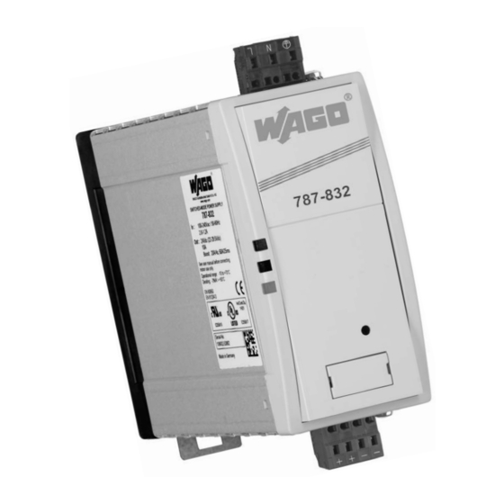
Abbildung zeigt den 787-832
This figure shows the 787-832
Eingang
line
3
L N PE
1
b
a
89
4
2
+ + – –
Ausgang
U out
load
–
89
1 2 3 4 5 6 7 8
Relais aktiv (Kontakt 4-5 geschlossen),
wenn Uout > typ. 0,85xUout.
Relay active (contact 4-5 closed), if
Uout > typ. 0.85xUout.
Safety measures before installation
Safety measures before installation
This equipment is to be protected against
improper use. Components are not to
be bent or isolation spacing changed, es-
pecially through handling and transport.
The contact with electrical components
and terminals is to be avoided. Always
disconnect the equipment from the mains
supply, before commencing installation or
wiring. The product description, technical
information in our main catalogue and the
marking on the equipment ratings plate
are to be observed.
Installation
Installation must be carried out accor-
ding to the prevailing local conditions
and safety regulations (e.g. VDE 0100)
national accident prevention regulations
(e.g. UVV-VBG4 or BGV A3) and the ge-
nerally accepted rules of technology. This
equipment is a component designed for
installation into electrical systems and
machines, and fulfils the requirements of
the low voltage guidelines (2014/35/EU).
In order to ensure sufficient convection,
follow installation clearances is recom-
mend: 40mm on top and bottom, 10mm
on the left and right side. When installed
into machinery, the normal operation is
forbidden until it is determined that the
machine fulfils the requirements of the
machinery guidelines (2006/42/EG).
EN 60204 must be observed. The EMC
requirements (2014/30/EU) must be ful-
filled before operation is commenced. The
observance of the required limitations for
the EMC legislation is the responsibility
of the manufacturer of the installation or
machinery.
9
Stand-by-input: The stand-by-input
allows targeted switch-off of the
power supply. By applying an external
DC voltage at the standby-input, the
output of the device is not released
and the power supply remains on
stand-by.
5
DIN 35 mm rail
6
7
Top Boost
Power
Strombegrenzung
Boost
Current limitation
Stufe 1
Stufe 2
Step 1
Step 2
+
Inenn
Irated
Unenn
Urated
0
Überstromphase
Overcurrent phase
t [sec]
Werbung

Verwandte Anleitungen für WAGO 787-818


Inhaltszusammenfassung für WAGO 787-818
- Seite 1 Components are not to re dürfen bei Transport und Handhabung be bent or isolation spacing changed, es- keine Bauelemente verbogen und/oder pecially through handling and transport. 787-818 787-832 Isolationsabstände verändert werden. EPSITRON -PRO-Power ® The contact with electrical components Die Berührung elektrischer Bauele-...
- Seite 2 Frequenzbereich Rated frequency range 50 – 60 Hz Eingangsnennstrom bei 100 / 240 Vac (unter Nennlast) 0,86 / 0,51 Aac (787-818 1,7 / 0,97 Aac (787-821 1,9 / 0,9 Aac (787-831) 5,1 / 2,3 Aac (787-834) Rated input current at 110 / 230 Vac (at nominal load)
- Seite 3 *** WAGO Serie 831: Mit Aderendhülse max. 6mm². Bei feindrähtigen Leitern bitte geeigneten Spleißschutz verwenden. *** WAGO Series 831: With ferrule max. 6mm². Please use suitable anti-splaying method for fine-stranded conductors. **** Maße ohne Anschlusstecker, Tiefe T ab Oberkante Tragschiene...