WAGO EPSITRON 862 Bedienungsanleitung
Quicklinks
deutsch /
english
Bedienungsanleitung /
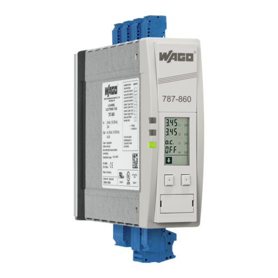
787-860
EPSITRON
®
787-862
Elektronischer Schutzschalter
Electronic fuse unit
Anschluss
Connection
T
Um Verwechslungen mit anderen
Anschlüssen zu vermeiden, verwenden Sie
ausschließlich die mitgelieferten Stecker.
Abbildung zeigt den 787-860
This figure shows the 787-860
1
c
b
a
2
3
9
4
Fern-Ein
Remote
1 2 3 4
ON ON 13 14
9
S1: offen, wenn mind. ein Kanal ausgelöst
S2: offen, wenn Kanal 2 ausgelöst
S3: offen, wenn Kanal 3 ausgelöst
S4: offen, wenn Kanal 4 ausgelöst
Instruction Manual
T
To reduce the risk of mistaking the
terminals, the supplied terminals must
be used.
7
DIN 35 mm
rail
8
U
in
S1
S2
S3
S4
RxPC TxPC
U
in
1 2 3 4 5 6 7 8
Pin 2 = RxPC
Pin 3 = TxPC
Pin 5 = GND
open, if min. one channel tripped
open, if channel 2 tripped
open, if channel 3 tripped
open, if channel 4 tripped
Installation
Installation
Sicherheitsmaßnahmen vor der
Installation
Das Betriebsmittel ist vor unzulässiger
Beanspruchung zu schützen. Insbeson-
dere dürfen bei Transport und Hand-
habung keine Bauelemente verbogen
und/oder Isolationsabstände verändert
werden. Die Berührung elektrischer
Bauelemente und Kontakte ist zu
vermeiden. Betriebsmittel immer im
spannungsfreien Zustand montieren und
verdrahten. Die Produktbeschreibung
und die technischen Hinweise in unserem
Hauptkatalog sowie die Aufschriften am
Betriebsmittel und auf dem Typenschild
sind zu beachten.
Installation
Die Installation ist entsprechend den
örtlichen Gegebenheiten, einschlägigen
Vorschriften (z.B. VDE 0100), nationalen
Unfallverhütungsvorschriften (z.B. UVV-
VBG4 bzw. BGV A3) und den anerkannten
Regeln der Technik durchzuführen. Dieses
elektrische Betriebsmittel ist eine Kom-
ponente, die zum Einbau in elektrische
Anlagen oder Maschinen bestimmt ist
und erfüllt die Anforderungen der Nie-
derspannungsrichtlinie (2006/98/EG).
Bei Einbau in Maschinen ist die Aufnahme
des bestimmungsgemäßen Betriebes
solange untersagt, bis festgestellt wurde,
dass die Maschine den Bestimmungen
der Maschinenrichtlinie (2006/42/EG)
entspricht. EN 60204 ist zu beachten.
Die Aufnahme des bestimmungsgemäßen
Betriebes ist nur bei Einhaltung der EMV-
Richtlinie (2004/108/EG) erlaubt. Die
Einhaltung der durch die EMV-Gesetz-
gebung geforderten Grenzwerte liegt in
der Verantwortung des Herstellers der
Anlage oder Maschine.
1
LED: Die grüne LED (a) leuchtet, sofern kein
Kanal ausgelöst hat. Die gelbe LED (b) zeigt
Warnungen an. Die rote LED (c) leuchtet, sofern
ein Kanal ausgelöst hat.
Display der Kontrolleinheit: Die Kontrolle der
Kanäle und die Änderung des Nennstroms über
das Display wird rückseitig erklärt.
3
Tasten: Linke Taste = vorwärts im Menü, rechte
Taste = zum Parametrisieren.
4
Eingang
5
Ausgang
6
Fern-Ein- und potentialfreier Meldekontakt:
13 14 potentialfreier Meldekontakt, konfi-
gurierbar über die Konfigurations-Software
759-860.
ON ON Fern-Ein Eingang, DC 24V-Eingänge zum
Wiedereinschalten ausgelöster Kanäle.
7
Montage: Setzen Sie das Modul mit der Trag-
schienenführung an die Oberkante der Trag-
8
schiene an und rasten Sie es nach unten ein.
Demontage: Ziehen Sie den Schnappriegel
mit Hilfe eines Schraubendrehers auf und
hängen Sie das Modul an der Unterkante der
Tragschiene aus.
9
Schnittstelle und Signalausgänge: Die
Schutzkappe ist zur Vermeidung statischer
Entladungen nur unter Anwendung von ESD-
Schutzmaßnahmen abzunehmen. Frei beleg-
barer Signalausgang, konfigurierbar per PC,
Verknüpfung mit potentialfreiem Meldekontakt,
werkseitig als Sammelfehlermeldung aller
Kanäle konfiguriert, Werkseitige Verknüpfung
mit den Kanälen 2 bis 4, Kommunikationsein-
und Ausgänge,
Eingangsspannung.
Die Schnittstelle ist nicht galvanisch getrennt.
Ein geeignetes Adapterkabel (787-890) können
Sie optional über WAGO beziehen. Die optionale
Konfigurations- und Visualisierungssoftware
(759-860) können Sie kostenlos unter
www.wago.com/epsitron herunterladen.
Bei Anschluss eines Relais an einen Signal-
ausgang muss zwingend eine Freilaufdiode
vorhanden sein.
Safety measures before installation
This equipment is to be protected against
improper use. Especially during handling
and transport no components should
be bent or isolation spacing be changed.
The contact with electrical components
and terminals is to be avoided. Always
disconnect the equipment from the mains
supply, before commencing installation or
wiring. The product description, technical
information in our main catalogue and the
marking on the equipment rating plate
are to be observed.
Installation
Installation must be carried out accor-
ding to the prevailing local conditions
and safety regulations (eg. VDE 0100),
national accident prevention regulations
(eg. UVV-VBG4 or BGV A3) and the gene-
rally accepted rules of technology. This
equipment is a component designed for
installation into electrical systems and
machines, and fulfils the requirements
of the low voltage guidelines (2006/98/
EG). When installed into machinery, the
normal operation is forbidden until it is
determined that the machine fulfils the
requirements of the machinery guide-
lines (2006/42/EG). EN 60204 must
be observed. The EMC requirements
(2004/108/EG) must be fulfilled before
operation is commenced. The obser-
vance of the required limitations for the
EMC legislation is the responsibility of
the manufacturer of the installation or
machinery.
1
LED: The green LED (a) lights when all channels
are active. The yellow LED (b) shows a warning.
The red LED (c) shows a fault condition.
2
The control unit display: The parameter
adjustments are described on the back of this
leaflet.
3
Buttons: Left button = forward in the menu,
right button = to alter parameter settings.
4
Input
5
Output
6
Remote on and potential free signal contact:
13 14 potential free signal contact can be
configured with the Configuration Software
759-860.
ON ON remote on input, DC 24V inputs for
restarting tripped channels.
7
Mounting: Place the module with the DIN rail
guide on the upper edge of the DIN rail, and snap
it in with a
8
downward motion.
Removing: Pull the snap lever open with the aid
of a screwdriver and slide the module out at the
lower edge of the DIN rail.
9
Interface and output signal port: The protec-
tive cap is to reduce the risk of static discharge
and should only be removed with the use of ESD
1
protective measures.
Free programmable
signal output can be configured with a PC,
1
combination with the potential free signal
contact is factory set as a combined fault report
234
for all channels,
Factory set combination
568
with the channels 2 to 4,
Communication
7
in and outputs
input voltage.
The interface has no galvanic separation and
should be only connected with a suitable adap-
ter cable (787-890) that are optionally available
from WAGO. The optionally software required
for configuration and visualization (759-860)
can be downloaded free of charge from
www.wago.com/epsitron. If a relay is to be con-
nected to a signal output then it is imperative
that a free running diode be used.

Verwandte Anleitungen für WAGO EPSITRON 862


Inhaltszusammenfassung für WAGO EPSITRON 862
- Seite 1 1 2 3 4 Konfigurations- und Visualisierungssoftware can be downloaded free of charge from (759-860) können Sie kostenlos unter www.wago.com/epsitron. If a relay is to be con- ON ON 13 14 www.wago.com/epsitron herunterladen. nected to a signal output then it is imperative Bei Anschluss eines Relais an einen Signal- that a free running diode be used.
- Seite 2 Kanalkontrolle und Nennstromänderung über das Display = mit diesem Befehl (linke Taste) kommen Sie zum nächsten Menüpunkt 3 , 4 5 I1 [A] 3 , 4 5 I2 [A] Allgemeine Funktionen Eingangsspannung o . c . I3 [A] Allgemein: Nur wenn die Tasten-Symbole im LC- Die aktuelle Eingangspannung wird angezeigt.
- Seite 3 Funktionen und Anwendungsbereiche Features and scope of operation Der elektronische Schutzschalter verteilt den Für die Signalisierung von Betriebszuständen besitzt Depending on the module version, the input current For signalization of the operating condition the Eingangsstrom auf 4 elektronisch überwachte das Modul neben einem Display vier aktive 24 Vdc is distributed to 4 electronically monitored outputs.
- Seite 4 WAGO Serie 831, max 10,0 mm² Terminals: WAGO multi plug system (++) WAGO series 831, max 10.0 mm² Anschlüsse: WAGO Multisteckersystem (Signal, --) WAGO Serie 231, max 2,5 mm² Terminals: WAGO multi plug system (signal, --) WAGO series 231, max 2.5 mm² Ausgang Output Ausgangsnennspannung...