Bpt XC/300 Bedienungs- Und Installationsanleitung
Quicklinks
B
M1
CNH
SW1
12.2003/2405-4700
XC/300
BPT S.p.A.
30020 Cinto Caomaggiore
Venezia/Italy
ISTRUZIONI PER L'USO
I
E INSTALLAZIONE
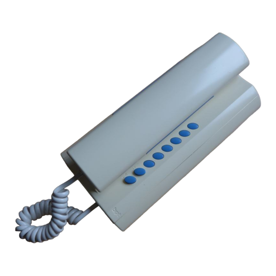
MODULO CITOFONO XC/300
È munito dei seguenti comandi (fig. 1):
•
Ausiliario
•
Apriporta (
1
)
(
1
) È possibile utilizzare questo coman-
do solo se l'apparecchio è attivo.
1
Funzione dei morsetti
Morsettiera M1
B linea
chiamata dal pianerottolo
–
massa
Funzione del ponticello SW1
(Attenuazione della chiamata)
Normalmente viene fornito inserito.
Togliere il ponticello SW1 (fig. 2) qua-
lora si voglia attenuare il volume della
nota di chiamata, oppure nel caso di
più derivati attivati dalla stessa chia-
mata.
Numero massimo di derivati attivati
dalla stessa chiamata:
- 3 con chiamata normale (ponticello
2
SW1 inserito);
- 2 con chiamata normale e 6 con
chiamata attenuata (ponticello SW1
non inserito).
Chiamata dal pianerottolo
L'apparecchio è provvisto di un
ingresso (morsetto
) per la chiama-
ta differenziata (es. dal pianerottolo)
a nota continua (2 s circa).
Caratteristiche tecniche
• Alimentazione: dalla stessa linea
dati.
• Assorbimento: 0,5 mA.
• Numero massimo di derivati che si
possono collegare all'alimentatore
3
XA/300LR: 200.
• Numero massimo di derivati che si
possono collegare a un posto
esterno X2: 64.
• Linea di collegamento audio/dati:
doppino non polarizzato Z = 100 Ω.
• Temperatura di funzionamento: da
0 °C a +35 °C.
Installazione del modulo citofono
Dopo aver tolto il mobile (vite frontale
di fig. 3, in basso) e la cornetta, fis-
sare la base direttamente al muro
(fig. 4A), oppure alla scatola incasso
(fig. 4B o 4C).
Su pareti non perfettamente piane
evitare il serraggio eccessivo delle
viti.
4A
Effettuare i collegamenti. Montare il
mobile, il cavo e la cornetta del
modulo citofono (fig. 5 e 6).
ATTENZIONE. Negli impianti con
XA/300LR si raccomanda di racco-
gliere i codici identificativi ID (SN),
applicati all'esterno del mobile, e
riportarli nelle tabelle allegate alle
apparecchiature XA/300LR, MPP/
300LR e IPC/300LR.
INSTRUCTIONS FOR USE
GB
AND INSTALLATION
HANDSET MODULE XC/300
It features the following controls (fig.
1):
•
Auxiliary
•
Door lock release (
1
)
(1) This control can only be used if the
unit is on.
Function of each terminal
Terminal block M1
B line
personal door-bell
–
ground
Function of jumper SW1
(Call attenuated)
Normally supplied ready inserted.
Remove the jumper SW1 (fig. 2) in
the event the volume of the call note
is to be attenuated, or if you have a
number of receivers activated by the
same call.
Maximum number of receivers acti-
vated by same call:
- 3 with normal call (jumper SW1
inserted);
- 2 with normal call and 6 with atte-
nuated call (jumper SW1 not inser-
ted).
Personal door-bell button
The receiver is fitted with a differen-
tiated call input (terminal
) (i.e.: for
personal door-bell) a continuous tone
call (approximately 2 s).
Technical features
• Power supply: from data line itself.
• Current demand: <0,5 mA.
• Maximum number of receivers that
can be connected to control unit
XA/300LR: 200.
• Maximum number of receivers that
can be connected to an X2 entry
panel: 64.
• Audio/data connection line: non
polarized twisted pair Z = 100 Ω.
• Working temperature range: 0 °C to
+35 °C.
Installation handset module
Having removed the casing (front
screw in fig. 5, bottom) and receiver,
fasten the housing directly to the wall
(fig. 4A) or to the embedding box (fig.
4B or 4C).
If walls are not perfectly flat, take
care not to overtighten screws.
Perform the wiring. Refit the casing,
the cable and the receiver of the
handset module (fig. 5 and 6).
WARNING.
In
installations
XA/300LR we recommend you gather
up the ID (SN) codes, applied on the
outside of the housing, and enter
them in the tables that come with the
XA/300LR,
MPP/300LR
IPC/300LR.
BEDIENUNGS- UND
D
INSTALLATIONSANLEITUNG
SPRECHMODUL XC/300
Mit
folgenden
Steuerfunktionen
ausgestattet (Abb. 1):
•
Zusatz
•
Türöffner (
1
)
(
1
) Diese Steuerfunktion ist nur bei
eingeschaltetem Gerät verwendbar.
Funktion der Klemmleisten
Klemmleiste M1
B Leitung
Anruf vom Treppenhaus
–
Masse
Belegungder der
Überbrückungsklemme SW1
(Abschwächung des Anrufs)
Wird gewöhnlich schon eingefügt
geliefert. Falls man die Lautstärke
des Ruftons herabsetzen möchte ist
die
Überbrückungsklemme
(Abb. 2) abzunehmen, oder mehrere
Sprechstellen über denselben Anruf
aktiviert werden.
Höchstanzahl von Sprechstellen, die
über denselben Ruf aktivierbar sind:
- 3
bei
normalem
brückungsklemme SW1 zwischen
geschaltet);
- 2 bei normalem Ruf und 6 bei
abgeschwächtem
Ruf
brückungsklemme SW1 nicht zwi-
schen geschaltet).
Technische Daten
• Stromversorgung: von derselben
Datenleitung.
• Stromaufnahme: 0,5 mA.
• Höchstanzahl von Sprechstellen,
die an das Netzgerät XA/300LR
anschließbar sind: 200.
• Höchstanzahl von Sprechstellen,
die an eine Außenstation X2 ansch-
ließbar sind: 64.
• Ton-/Datenanschlussleitung: unge-
polte Telefonschleife Z = 100 Ω.
• Betriebstemperatur: von 0 °C bis
+35 °C.
Einbau des Sprechmoduls
Gehäuse (Vorderschraube der Abb.
3, unten) und Hörer abnehmen, Basis
direkt an die Wand (Abb. 4A) oder an
den UP-Kasten (Abb. 4B oder 4C)
befestigen.
Bei nicht ganz ebenen Wänden soll-
ten die Schrauben nicht zu fest ange-
schraubt werden.
Anschlüsse vornehmen. Gehäuse,
Kabel und Hörer des Sprechmoduls
anbringen (Abb. 5 und 6).
Etagenruf
Das
Gerät
verfügt
Eingang (Klemmleiste
Anruf unterscheidung (z.B. Etagen-
ruf) mit Dauertoner (ca. 2 s).
ACHTUNG. In Anlagen mit XA/300LR
wird angeraten, die an der Element-
außenseite befindlichen ID (SN) -
with
Erkennungscodes in die Tabellen ein-
zutragen, die zusammen mit den
Geräten XA/300LR, MPP/300LR und
IPC/300LR geliefert werden.
and
SW1
Ruf
(Über-
(Über-
über
einen
) für die
1

Verwandte Anleitungen für Bpt XC/300


Inhaltszusammenfassung für Bpt XC/300
- Seite 1 • Zusatz INSTRUCTIONS FOR USE • AND INSTALLATION Türöffner ( ) Diese Steuerfunktion ist nur bei eingeschaltetem Gerät verwendbar. HANDSET MODULE XC/300 It features the following controls (fig. Funktion der Klemmleisten Klemmleiste M1 • Auxiliary • ISTRUZIONI PER L’USO B Leitung...
- Seite 2 INSTRUCTIONS POUR L’EMPLOI INSTRUCCIONES PARA LA ISTRUÇÕES PARA O USO ET L’INSTALLATION UTILIZACIÓN Y INSTALACIÓN E INSTALAÇÃO MÓDULO TELEFONE XC/300 MODULE PORTIER MÓDULO TELEFONO XC/300 Está dotado dos seguintes coman- Dispone de los siguientes comandos ÉLECTRONIQUE XC300 dos (fig. 1): Il comprend les commandes suivan- (fig.