TECNOINOX CP35G7 Handbuch
Gas-nudelkocher
Inhaltsverzeichnis
Verfügbare Sprachen
Verfügbare Sprachen
Quicklinks
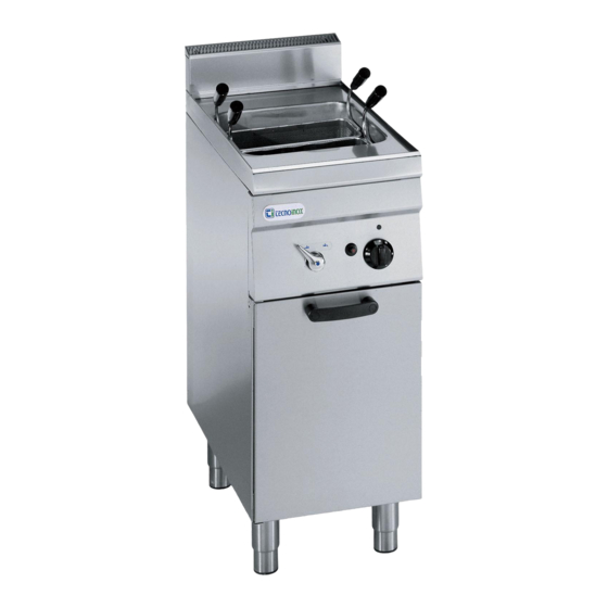
Dimensioni esterne, External dimensions, Außenmaße, Вешние Размеры, Dimensions extérieures,
Dimensiones externas (mm)
Capacità vasca, Tub capacity, Beckeninhalt, Вместимость Емкости, Capacité cuve, Capacidad recipiente
Potenza installata, Installed power, Nennleistung, Установленная Мощность, Puissance installée, Potencia instalada
Dimensioni vasca, Tub dimensions, Beckenmaße, Размер емкости, Dimensions cuve, Dimensiones recipiente
IN
ø ½"
Attacco alimentazione acqua, Water inlet connection, Wasseranschluss, Контакт питания воды, Arrivée eau, Entrada agua.
OUT ø 1"
Attacco scarico vasca, Water drain connection, Wasserauslaufanschluss, Контакт слива емкости, Evaquation eau, Salida agua.
G
G ½"
Attacco gas, Gas inlet connection, Gasanschluss, Контакт газа, Arrivée gaz, Entrada gas. (ISO 228-1 / EN 10226-1)
N
Morsetto equipotenziale, Unipotential earthing connection, Potentialausgleich, Эквипотенциальная клеммная коробка, Vis équipotentiel, Tornillo equipotencial.
06|2011
L
P
H
Fig.1 | Abb.1| рис.1
II
CP35G7
350
700
850
23 lt
10 kW
10 + 10 kW
GN 2/3
2× (GN 2/3)
CP70G7
700
700
850
23 + 23 lt
5410.264.00
Inhaltsverzeichnis

Verwandte Anleitungen für TECNOINOX CP35G7


Inhaltszusammenfassung für TECNOINOX CP35G7
- Seite 3 Fig.2 | Abb. 2 | рис.2 (PC35G7 – PC70G7) Fig.2 | Abb.2 | рис.2 (PC4FG7 – PC8FG7) Fig.3 | Abb.3 | рис.3 Fig.4 | Abb.4 | рис.4 Fig.5 | Abb.5 | рис.5 Fig.6 | Abb.6 | рис.6 Fig.7 | Abb.7 | рис.7 06|2011 5410.264.00...
-
Seite 18: Allgemeine Anmerkungen
Das Zusatzschild, ebenfalls aus selbstklebender Polyesterfolie, ist neben Nudelkocher der Kategorie II2ELL3B/P. dem Typenschild angebracht und enthält alle Informationen über die Einstellung des Gerätes. Das Gerätemodell CP35G7-CP4FG7 ist mit Das Typenschild aus selbsthaftendem Polyester befindet sich einem Brenner und einer Gasanschlussrampe ausgestattet. Das hinter der Bedienblende “T”... -
Seite 19: Anschluss An Die Wasserleitung
Die Wasseranschlussleitung anschließen; einen Absperrhahn und einen 1,5 bar versorgt werden. Siebfilter einbauen. Abgasführung Für die Geräte CP35G7-CP4FG7 (Typ A1) und CP70G7-CP8FG7 (Typ A1, B21) ist kein Kaminanschluss erforderlich, wobei die Aufstellung unter einer Dunstabzugshaube jedoch empfehlenswert ist. Druckkontrolle Der Leitungsdruck muss folgenden Daten entsprechen. - Seite 20 Teil 2 Umstellung und Anpassung Die Umstellung auf eine andere Gasart z.B. von Erdgas auf Flüssiggas Nach jeder Umstellung oder Anpassung ist eine Funktionskontrolle erfolgt durch den Austausch der Hauptbrenner-, Bypass- und vorzunehmen und das Zusatzschild entsprechend der erfolgten Zündbrennerdüsen. Alle Düsen sind mit einer Ziffer (Durchmesser in Umstellung bzw.
- Seite 21 Teil 3 Gebrauch Anfüllen des Beckens: Sicherstellen, dass der Wasserablaufhahn “C” (Abb. 2) im ACHTUNG! Geräteinneren geschlossen („horizontal“) ist. Das Gerät nie trocken betreiben. Das Wasser über den Drehschalter “W” (Abb. 2) einfüllen. Ein- und Ausschalten des Brenners ● Den Drehschalter “A” (Abb. 4) drücken und von “ ”...
-
Seite 22: Austausch Von Teilen
Funktionsprüfung Das Gerät ist vor der Übergabe an den Benutzer auf nachfolgende Die Flamme muss eine blaue Farbe, ohne gelbe Spitzen, aufweisen und Punkte zu kontrollieren. an der Basis stabil brennen. THERMISCHE LEISTUNG Wenn das Flammenbild gelb durchzogen ist, ist die Primärluft nicht Überprüfen, ob die am Aufstellungsort vorhandene Gasart und der Druck richtig eingestellt. -
Seite 23: Wartung
Teil 4 Wartung und Reinigung Reinigung und Instandhaltung Glaspapier oder Schmirgelpapier sollten bei der Reinigung nicht REINIGUNG: verwendet werden; man kann in besonderen Fällen pulverförmigen ACHTUNG: Die Reinigung ist nur bei abgekühltem Gerät vorzunehmen. Bimsstein verwenden; bei stärkerer Verschmutzung empfehlen wir die Benutzung von Schwämmen (z.B.