Inhaltsverzeichnis
Werbung
Version 1.0
Published October 2016
Copyright©2016 ASRock INC. All rights reserved.
Copyright Notice:
No part of this documentation may be reproduced, transcribed, transmitted, or
translated in any language, in any form or by any means, except duplication of
documentation by the purchaser for backup purpose, without written consent of
ASRock Inc.
Products and corporate names appearing in this documentation may or may not
be registered trademarks or copyrights of their respective companies, and are used
only for identification or explanation and to the owners' benefit, without intent to
infringe.
Disclaimer:
Specifications and information contained in this documentation are furnished for
informational use only and subject to change without notice, and should not be
constructed as a commitment by ASRock. ASRock assumes no responsibility for
any errors or omissions that may appear in this documentation.
With respect to the contents of this documentation, ASRock does not provide
warranty of any kind, either expressed or implied, including but not limited to
the implied warranties or conditions of merchantability or fitness for a particular
purpose.
In no event shall ASRock, its directors, officers, employees, or agents be liable for
any indirect, special, incidental, or consequential damages (including damages for
loss of profits, loss of business, loss of data, interruption of business and the like),
even if ASRock has been advised of the possibility of such damages arising from any
defect or error in the documentation or product.
This device complies with Part 15 of the FCC Rules. Operation is subject to the following
two conditions:
(1) this device may not cause harmful interference, and
(2) this device must accept any interference received, including interference that
may cause undesired operation.
CALIFORNIA, USA ONLY
The Lithium battery adopted on this motherboard contains Perchlorate, a toxic substance
controlled in Perchlorate Best Management Practices (BMP) regulations passed by the
California Legislature. When you discard the Lithium battery in California, USA, please
follow the related regulations in advance.
"Perchlorate Material-special handling may apply, see www.dtsc.ca.gov/hazardouswaste/
perchlorate"
ASRock Website: http://www.asrock.com
Werbung
Inhaltsverzeichnis

Verwandte Anleitungen für ASROCK Z270 Extreme4


Inhaltszusammenfassung für ASROCK Z270 Extreme4
- Seite 1 (including damages for loss of profits, loss of business, loss of data, interruption of business and the like), even if ASRock has been advised of the possibility of such damages arising from any defect or error in the documentation or product.
- Seite 2 You are also entitled to have the goods repaired or replaced if the goods fail to be of acceptable quality and the failure does not amount to a major failure. If you require assistance please call ASRock Tel : +886-2-28965588 ext.123 (Standard International call charges apply) The terms HDMI™...
-
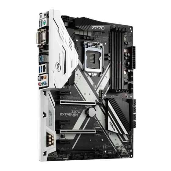
Seite 3: Motherboard-Layout
Z270 Extreme4 Motherboard Layout RoHS CPU_FAN1 ATX12V1 CPU_OPT/W_PUMP M2_3 HDMI1 USB 3.1 T: USB31_TA_1 B: USB31_TC_1 USB 3.0 Top: T: USB3 RJ-45 B: USB4 CHA_FAN2 CHA_FAN1 PCIE1 PCIE2 CMOS Z270 Intel Battery EXTREME4 Z270 Purity PCIE3 Sound 4 PCIE4 PCIE5... - Seite 4 No. Description ATX 12V Power Connector (ATX12V1) CPU Fan Connector (CPU_FAN1) CPU Fan / Waterpump Fan Connector (CPU_OPT/W_PUMP) 2 x 288-pin DDR4 DIMM Slots (DDR4_A1, DDR4_B1) 2 x 288-pin DDR4 DIMM Slots (DDR4_A2, DDR4_B2) ATX Power Connector (ATXPWR1) USB 3.0 Header (USB3_7_8) Chassis Fan Connector (CHA_FAN2) USB 3.0 Header (USB3_5_6) SATA3 Connectors (SATA3_4_5)
- Seite 5 Z270 Extreme4 I/O Panel No. Description No. Description PS/2 Mouse/Keyboard Port (PS2_KB1) Optical SPDIF Out Port D-Sub Port (VGA1) USB 3.0 Ports (USB3_34)*** LAN RJ-45 Port* USB 3.1 Type-A Port (USB31_TA_1) Central / Bass (Orange) USB 3.1 Type-C Port (USB31_TC_1)
- Seite 6 * There are two LEDs on each LAN port. Please refer to the table below for the LAN port LED indications. ACT/LINK LED SPEED LED LAN Port Activity / Link LED Speed LED Status Description Status Description No Link 10Mbps connection Blinking Data Activity Orange...
-
Seite 7: Package Contents
If you require technical support related to this mother- board, please visit our website for specific information about the model you are using. You may find the latest VGA cards and CPU support list on ASRock’s website as well. ASRock website http://www.asrock.com. - Seite 8 * 3866+(OC) memory frequency can only be achieved when a single memory module is installed (Single channel memory). * Please refer to Memory Support List on ASRock's website for more information. (http://www.asrock.com/) ** 7 Gen Intel® CPU supports DDR4 up to 2400; 6 Gen Intel®...
- Seite 9 • 7.1 CH HD Audio with Content Protection (Realtek ALC1220 Audio Codec) • Premium Blu-ray Audio support • Supports Surge Protection (ASRock Full Spike Protection) • Supports Purity Sound - Nichicon Fine Gold Series Audio Caps - 120dB SNR DAC with Differential Amplifier - TI®...
- Seite 10 - AURA RGB LED • Supports DTS Connect • Gigabit LAN 10/100/1000 Mb/s • Giga PHY Intel® I219V • Supports Wake-On-LAN • Supports Lightning/ESD Protection (ASRock Full Spike Protection) • Supports Energy Efficient Ethernet 802.3az • Supports PXE Rear Panel • 2 x Antenna Ports...
- Seite 11 M.2 PCI Express module up to Gen3 x4 (32 Gb/s)** ** Supports Intel® Optane Technology ** Supports NVMe SSD as boot disks ** Supports ASRock U.2 Kit Connector • 1 x COM Port Header • 1 x TPM Header • 1 x Power LED and Speaker Header...
-
Seite 12: Hardware Monitor
* To install Windows® 7 OS, a modified installation disk with xHCI drivers packed into the ISO file is required. Please refer to page 179 for more detailed instructions. * For the updated Windows® 10 driver, please visit ASRock’s website for details: http://www.asrock.com Certifica- • FCC, CE, WHQL, RCM, BSMI... - Seite 13 Z270 Extreme4 * For detailed product information, please visit our website: http://www.asrock.com Please realize that there is a certain risk involved with overclocking, including adjusting the setting in the BIOS, applying Untied Overclocking Technology, or using third-party overclocking tools. Overclocking may affect your system’s stability, or even cause damage to the components and devices of your system.
- Seite 14 Chapter 2 Installation This is an ATX form factor motherboard. Before you install the motherboard, study the configuration of your chassis to ensure that the motherboard fits into it. Pre-installation Precautions Take note of the following precautions before you install motherboard components or change any motherboard settings.
-
Seite 15: Installing The Cpu
Z270 Extreme4 2.1 Installing the CPU 1. Before you insert the 1151-Pin CPU into the socket, please check if the PnP cap is on the socket, if the CPU surface is unclean, or if there are any bent pins in the socket. Do not force to insert the CPU into the socket if above situation is found. - Seite 17 Z270 Extreme4 Please save and replace the cover if the processor is removed. The cover must be placed if you wish to return the motherboard for after service.
- Seite 18 2.2 Installing the CPU Fan and Heatsink...
- Seite 19 Z270 Extreme4 2.3 Installing Memory Modules (DIMM) This motherboard provides four 288-pin DDR4 (Double Data Rate 4) DIMM slots, and supports Dual Channel Memory Technology. 1. For dual channel configuration, you always need to install identical (the same brand, speed, size and chip-type) DDR4 DIMM pairs.
- Seite 21 Z270 Extreme4 2.4 Expansion Slots (PCI Express Slots) There are 6 PCI Express slots on the motherboard. Before installing an expansion card, please make sure that the power supply is switched off or the power cord is unplugged. Please read the documentation of the expansion card and make necessary hardware settings for the card before you start the installation.
- Seite 22 2.5 Jumpers Setup The illustration shows how jumpers are setup. When the jumper cap is placed on the pins, the jumper is “Short”. If no jumper cap is placed on the pins, the jumper is “Open”. The illustration shows a 3-pin jumper whose pin1 and pin2 are “Short” when a jumper cap is placed on these 2 pins.
- Seite 23 Z270 Extreme4 2.6 Onboard Headers and Connectors Onboard headers and connectors are NOT jumpers. Do NOT place jumper caps over these headers and connectors. Placing jumper caps over the headers and connectors will cause permanent damage to the motherboard. System Panel Header...
- Seite 24 Power LED and Speaker Please connect the SPEAKER DUMMY Header chassis power LED and DUMMY (7-pin SPK_PLED1) the chassis speaker to this (see p.1, No. 15) header. PLED+ PLED+ PLED- Serial ATA3 Connectors These eight SATA3 (SATA3_4_5: connectors support SATA see p.1, No.
- Seite 25 Z270 Extreme4 USB 3.0 Header Besides four USB 3.0 ports Vbus Vbus Vbus IntA_PB_SSRX- (19-pin USB3_5_6) on the I/O panel, there IntA_PA_SSRX- IntA_PB_SSRX+ IntA_PA_SSRX+ (see p.1, No. 9) are two headers on this IntA_PB_SSTX- IntA_PA_SSTX- IntA_PB_SSTX+ (19-pin USB3_7_8) motherboard. Each USB...
- Seite 26 Chassis Optional/Water This motherboard FAN_VOLTAGE Pump Fan Connector provides two 4-Pin water FAN_SPEED (4-pin CHA_FAN3/W_ cooling chassis fan FAN_SPEED_CONTROL PUMP) connectors. If you plan to (see p.1, No. 16) connect a 3-Pin chassis water cooler fan, please connect it to Pin 1-3. CPU Fan Connector This motherboard pro- FAN_SPEED_CONTROL...
- Seite 27 Z270 Extreme4 Thunderbolt AIC Please connect a Thunderbolt™ Connectors add-in card (AIC) to the (5-pin TB1) Thunderbolt AIC connector via DUMMY (see p.1, No. 23) the GPIO cable. I2C_DATA (10-pin TB2) *Please install the Thunderbolt™ I2C_CLOCK (see p.1, No. 22) AIC card to PCIE6 (default slot).
- Seite 28 2.7 M.2 WiFi/BT Module Installation Guide The M.2 Socket (Key E) supports type 2230 WiFi/BT module. Installing the WiFi/BT module Step 1 Prepare a type 2230 WiFi/BT module and the screw. Step 2 Find the nut location to be used. Module Type: Type2230 PCB Length: 3cm Step 3...
- Seite 29 Z270 Extreme4 Step 4 Tighten the screw with a screwdriver to secure the module into place. Please do not overtighten the screw as this might damage the module.
- Seite 30 2.8 M.2_SSD (NGFF) Module Installation Guide The M.2, also known as the Next Generation Form Factor (NGFF), is a small size and versatile card edge connector that aims to replace mPCIe and mSATA. The Ultra M.2 Socket (M2_1 and M2_2) supports SATA3 6.0 Gb/s module and M.2 PCI Express module up to Gen3 x4 (32 Gb/s).
- Seite 31 Z270 Extreme4 Step 3 Move the standoff based on the module type and length. The standoff is placed at the nut location D by default. Skip Step 3 and 4 and go straight to Step 5 if you are going to use the default nut.
- Seite 32 Step 6 Tighten the screw with a screwdriver to secure the module into place. Please do not overtighten the screw NUT2 NUT1 as this might damage the module. M.2_SSD (NGFF) Module Support List Vendor Size Interface Length ADATA 128GB SATA3 2280 AXNS381E-128GM-B ADATA...
- Seite 33 Z270 Extreme4 Vendor Size Interface Length V-Color 240GB SATA3 2280 VLM100-240G-2280B-RD V-Color 240GB SATA3 2280 VSM100-240G-2280 For the latest updates of M.2_SSD (NFGG) module support list, please visit our website for details: http://www.asrock.com...
-
Seite 34: Einleitung
1 Einleitung Vielen Dank, dass Sie sich für das Z270 Extreme4 von ASRock entschieden haben – ein zuverlässiges Motherboard, das konsequent unter der strengen Qualitätskontrolle von ASRock hergestellt wurde. Es liefert ausgezeichnete Leistung mit robustem Design, das ASRock Streben nach Qualität und Beständigkeit erfüllt. -
Seite 35: Technische Daten
Prozessoren der 7. und 6. Generation (Sockeö 1151) • Digi Power design • 10-Leistungsphasendesign • Unterstützt Intel® Turbo Boost 2.0-Technologie • Unterstützt CPUs mit freiem Multiplikator der Intel® K-Serie • Unterstützt ASRock BCLK-Übertaktung (voller Bereich) ® Chipsatz • Intel Z270 Speicher • Dualkanal-DDR4-Speichertechnologie... - Seite 36 DVI-D- und HDMI-Ports Audio • 7.1-Kanal-HD-Audio mit Inhaltsschutz (Realtek ALC1220- Audiocodec) • Erstklassige Blu-ray-Audiounterstützung • Unterstützt Überspannungsschutz (ASRock Full Spike Protection) • Unterstützt Purity Sound - Nichicon-Audiokappen der Fine Gold-Serie - 120-dB-SRV-DAC mit Differentialverstärker - TI® NE5532 – erstklassiger Headset-Verstärker für Audioanschluss an der Frontblende (unterstützt Headsets mit...
- Seite 37 • 1 x HDMI-Port • 1 x Optischer SPDIF-Ausgang • 1 x USB 3.1-Typ-A-Port (10 Gb/s) (ASMedia ASM2142) (unterstützt Schutz gegen elektrostatische Entladung (ASRock Full Spike Protection)) • 1 x USB 3.1-Typ-C-Port (10 Gb/s) (ASMedia ASM2142) (unterstützt Schutz gegen elektrostatische Entladung (ASRock Full Spike Protection)) • 4 x USB 3.0-Ports (Intel®...
-
Seite 38: Anschluss
2230-/2242-/2260-/2280-/22110-M.2-SATA-III-6,0-Gb/ s-Modul und M.2-PCI-Express-Modul bis Gen3 x 4 (32 Gb/s)** ** Unterstützt Intel® Optane -Technologie ** Unterstützt NVMe-SSD als Bootplatte ** Unterstützt ASRock U.2-Kit Anschluss • 1 x COM-Anschluss-Stiftleiste • 1 x TPM-Stiftleiste • 1 x Betrieb-LED- und Lautsprecher-Stiftleiste • 1 x Aura-RGB-LED-Stiftleiste • 1 x CPU-Lüfteranschluss (4-polig) -
Seite 39: Hardware-Überwachung
Z270) (unterstützt Schutz gegen elektrostatische Entladung (ASRock Full Spike Protection)) • 1 x USB-3.0-Stiftleiste (unterstützt 2 USB-3.0-Ports) (AS- Media ASM1074-Hub) (unterstützt Schutz gegen elektro- statische Entladung (ASRock Full Spike Protection)) BIOS-Funk- • 2 x AMI-UEFI-Legal-BIOS mit Unterstützung mehrspra- tion chiger grafischer Benutzerschnittstellen (1 x Haupt-BIOS und 1 x Ausfall-BIOS) • Unterstützt UEFI-Technologie (zuverlässige Sicherung) - Seite 40 • FCC, CE, WHQL, RCM, BSMI • ErP/EuP ready (ErP/EuP ready-Netzteil erforderlich) * Detaillierte Produktinformationen finden Sie auf unserer Webseite: http://www.asrock.com Bitte beachten Sie, dass mit einer Übertaktung, zu der die Anpassung von BIOS-Einstellungen, die Anwendung der Untied Overclocking Technology oder die Nutzung von Übertaktung- swerkzeugen von Drittanbietern zählen, bestimmte Risiken verbunden sind.
-
Seite 41: Jumpereinstellung
Z270 Extreme4 1.3 Jumpereinstellung Die Abbildung zeigt, wie die Jumper eingestellt werden. Wenn die Jumper-Kappe auf den Kontakten angebracht ist, ist der Jumper „kurzgeschlossen“. Wenn keine Jumper- Kappe auf den Kontakten angebracht ist, ist der Jumper „offen“. Die Abbildung zeigt einen 3-poligen Jumper, dessen Kontakt 1 und Kontakt 2 „kurzgeschlossen“... -
Seite 42: Integrierte Stiftleisten Und Anschlüsse
1.4 Integrierte Stiftleisten und Anschlüsse Integrierte Stiftleisten und Anschlüsse sind KEINE Jumper. Bringen Sie KEINE Jumper-Kappen an diesen Stiftleisten und Anschlüssen an. Durch Anbringen von Jumper-Kappen an diesen Stiftleisten und Anschlüssen können Sie das Motherboard dauerhaft beschädigen. Systemblende-Stiftleiste Verbinden Sie PLED+ PLED- (9-polig, PANEL1) -
Seite 43: Serial-Ata-Iii-Anschlüsse
Z270 Extreme4 Betrieb-LED- und Bitte verbinden Sie die Be- SPEAKER DUMMY Lautsprecher-Stiftleiste trieb-LED des Gehäuses und DUMMY (7-polig, SPK_PLED1) den Gehäuselautsprecher (siehe S. 1, Nr. 15) mit dieser Stiftleiste. PLED+ PLED+ PLED- Serial-ATA-III-Anschlüsse Diese acht SATA-III- (SATA3_4_5: Anschlüsse unterstützen siehe S. 1, Nr. 10) SATA-Datenkabel für... - Seite 44 USB 3.0-Stiftleiste Neben vier USB 3.0-Ports Vbus Vbus Vbus IntA_PB_SSRX- (19-polig, USB3_5_6) an der E/A-Blende befinden IntA_PA_SSRX- IntA_PB_SSRX+ IntA_PA_SSRX+ (siehe S. 1, Nr. 9) sich zwei Stiftleisten an IntA_PB_SSTX- IntA_PA_SSTX- IntA_PB_SSTX+ (19-polig, USB3_7_8) diesem Motherboard. Jede IntA_PA_SSTX+ IntA_PB_D- (siehe S. 1, Nr. 7) USB 3.0-Stiftleiste kann zwei IntA_PA_D- IntA_PB_D+...
- Seite 45 Z270 Extreme4 Optionales-Gehäuse-/ Dieses Motherboard FAN_VOLTAGE bietet zwei 4-polige Wasserpumpen- FAN_SPEED Wasserkühlung-Ge- Lüfteranschluss FAN_SPEED_CONTROL häuselüfteranschlüsse. (4-polig, CHA_FAN3/W_ Falls Sie einen 3-poligen PUMP) Gehäuse-Wasserkühlerlüfter (siehe S. 1, Nr. 16) anschließen möchten, verbinden Sie ihn bitte mit Kontakt 1 bis 3. CPU-Lüfteranschluss...
- Seite 46 Thunderbolt- Bitte verbinden Sie eine Thunderbolt™- Erweiterungskartenanschlüsse Erweiterungskarte über (5-polig, TB1) das GPIO-Kabel mit (siehe S. 1, Nr. 23) diesem Thunderbolt-AIC- DUMMY (10-polig, TB2) I2C_DATA Anschluss. I2C_CLOCK (siehe S. 1, Nr. 22) *Bitte installieren Sie die Thunderbolt™-AIC-Karte am PCIE6 (Standardsteckplatz). *Es wird nur eine SLP_S4# Thunderbolt-AIC-Karte...
-
Seite 47: Contenu De L'emballage
Si vous avez besoin d’une assistance technique pour votre carte mère, veuillez visiter notre site Internet pour plus de détails sur le modèle que vous utilisez. La liste la plus récente des cartes VGA et des processeurs pris en charge est également disponible sur le site Internet de ASRock. Site Internet ASRock http://www.asrock.com. - Seite 48 • Alimentation à 10 phases • Prend en charge la technologie Intel® Turbo Boost 2.0 • Prend en charge les processeurs débloqués de la série K Intel® • Prend en charge l’ o verclocking ASRock BCLK Full-range ® Chipset • Intel Z270 Mémoire...
- Seite 49 • Audio 7.1 CH HD avec protection du contenu (codec audio Realtek ALC1220) • Compatible audio Blu-ray Premium • Protection contre les surtensions (Protection complète contre les pics ASRock) • Prend en charge Purity Sound - Couvercles audio série en or fin Nichicon - 120dB SNR DAC avec amplificateur différentiel - Amplificateur de casque TI®...
- Seite 50 (Protection contre les décharges électrostatiques (Protection complète contre les pics ASRock)) • 4 x ports USB 3.0 (Intel® Z270) (Protection contre les décharges électrostatiques (Protection complète contre les pics ASRock)) • 1 x port RJ-45 LAN avec LED (LED ACT/LIEN et LED VITESSE) • Connecteurs jack audio HD : Haut-parleur arrière / central /...
- Seite 51 Express jusqu'à Gen3 x4 (32 Gb/s)** ** Prend en charge Intel® Optane Technology ** Prend en charge les SSD NVMe comme disques de démarrage ** Prend en charge le kit ASRock U.2 Connec- • 1 x embase pour port COM • 1 x embase TPM teur • 1 x prise DEL d’alimentation et haut-parleur...
- Seite 52 • 1 x embase USB 3.0 (2 ports USB 3.0 pris en charge) (concen- trateur ASMedia ASM1074) (Protection contre les décharges électrostatiques (Protection complète contre les pics ASRock)) • 2 x BIOS UEFI AMI légaux avec prise en charge interface Caractéris-...
- Seite 53 Z270 Extreme4 * pour des informations détaillées de nos produits, veuillez visiter notre site : http://www.asrock.com Il est important de signaler que l’ o vercloking présente certains risques, incluant des modifi- cations du BIOS, l’ a pplication d’une technologie d’ o verclocking déliée et l’utilisation d’ o utils d’...
- Seite 54 1.3 Configuration des cavaliers (jumpers) L’illustration ci-dessous vous renseigne sur la configuration des cavaliers (jumpers). Lorsque le capuchon du cavalier est installé sur les broches, le cavalier est « court- circuité ». Si le capuchon du cavalier n’ e st pas installé sur les broches, le cavalier est « ouvert ».
- Seite 55 Z270 Extreme4 1.4 Embases et connecteurs de la carte mère Les embases et connecteurs situés sur la carte NE SONT PAS des cavaliers. Ne placez JAMAIS de capuchons de cavaliers sur ces embases ou connecteurs. Placer un capuchon de cavalier sur ces embases ou connecteurs endommagera irrémédiablement votre carte mère.
- Seite 56 Prise DEL d’alimentation Veuillez brancher la DEL SPEAKER DUMMY et haut-parleur d'alimentation du châssis DUMMY (SPK_PLED1 à 7 broches) et le haut-parleur du (voir p.1, No. 15) châssis sur ce connecteur. PLED+ PLED+ PLED- Connecteurs Serial ATA3 Ces huit connecteurs (SATA3_4_5: SATA3 sont compatibles voir p.1, No.
- Seite 57 Z270 Extreme4 Embases USB 3.0 En plus des quatre ports Vbus Vbus Vbus IntA_PB_SSRX- (USB3_5_6 à 19 broches) USB 3.0 sur le panneau E/S, IntA_PA_SSRX- IntA_PB_SSRX+ IntA_PA_SSRX+ (voir p.1, No. 9) cette carte mère est dotée IntA_PB_SSTX- IntA_PA_SSTX- IntA_PB_SSTX+ (USB3_7_8 à 19 broches) de deux embases.
- Seite 58 Connecteur du ventilateur Cette carte mère est dotée FAN_VOLTAGE de deux connecteurs pour de châssis optionnel/ FAN_SPEED ventilateur de châssis à pompe à eau FAN_SPEED_CONTROL refroidissement par eau à 4 (CHA_FAN3/W_PUMP à broches. Si vous envisagez 4 broches) de connecter un ventilateur (voir p.1, No.
- Seite 59 Z270 Extreme4 Connecteurs Thunderbolt Veuillez connecter une carte d’ e xtension (AIC) Thunderbolt™ au connecteur (TB1 à 5 broches) AIC Thunderbolt via le câble DUMMY (voir p.1, No. 23) GPIO. I2C_DATA (TB2 à 10 broches) I2C_CLOCK *Veuillez installer la carte (voir p.1, No.
-
Seite 60: Contenuto Della Confezione
Web di ASRock senza ulteriore preavviso. Per il supporto tecnico correlato a questa scheda madre, visitare il nostro sito Web per informazioni specifiche relative al modello attualmente in uso. - Seite 61 è installato un singolo modulo di memoria (memoria a canale singolo). * Per maggiori informazioni fare riferimento all'elenco dei supporti di memoria sul sito di ASRock. (http://www.asrock. com/) ** 7 Gen Intel® CPU supporta DDR4 2400 in modo nativo; 6 Gen Intel®...
- Seite 62 • Audio HD a 7,1 canali con Content Protection (codec audio Realtek ALC1220) • Supporto audio Blu-ray Premium • Supporto protezione da sovratensione (protezione completa ASRock dai picchi di corrente) • Supporto di Purity Sound - Cappucci audio Nichicon serie Fine Gold - 120dB SNR DAC con amplificatore differenziale - TI®...
- Seite 63 • 1 x porta uscita SPDIF ottico • 1 x Porta USB 3.1 di tipo A (10 Gb/s) (ASMedia ASM2142) (Supporto protezione ESD (protezione ASRock Full Spike)) • 1 x Porta USB 3.1 di tipo C (10 Gb/s) (ASMedia ASM2142) (Supporto protezione ESD (protezione ASRock Full Spike)) • 4 x Porte USB 3.0 (Intel®...
- Seite 64 (ASRock Full Spike Protection)) • 1 x Collettore USB 3.0 (supporto di 2 porte USB 3.0) (hub ASMedia ASM1074) (supporto protezione da scariche elet- trostatiche (ESD) (protezione completa ASRock dai picchi di corrente)) Funzionalità • 2 x AMI UEFI Legal BIOS con supporto interfaccia multi-...
- Seite 65 • ErP/EuP Ready (è necessaria alimentazione ErP/EuP ready) * Per informazioni dettagliate sul prodotto, visitare il nostro sito Web: http://www.asrock.com Prestare attenzione al potenziale rischio previsto nella pratica di overclocking, inclusa la regolazione delle impostazioni nel BIOS, l'applicazione di tecnologia di Untied Overclocking o l'utilizzo di strumenti di overclocking di terze parti.
- Seite 66 1.3 Impostazione jumper L'illustrazione mostra in che modo vengono impostati i jumper. Quando il cappuccio del jumper è posizionato sui pin, il jumper è "cortocircuitato". Se sui pin non è posizionato alcun cappuccio del jumper, il jumper è "aperto". L'illustrazione mostra un jumper a 3 pin i cui pin1 e pin2 sono "cortocircuitati"...
- Seite 67 Z270 Extreme4 1.4 Header e connettori sulla scheda Gli header e i connettori sulla scheda NON sono jumper. NON posizionare cappucci del jumper su questi header e connettori. Il posizionamento di cappucci del jumper su header e connettori provocherà danni permanenti alla scheda madre.
- Seite 68 Connettore LED Collegare i LED alimen- SPEAKER DUMMY alimentazione e tazione e l’altoparlante a DUMMY altoparlante questo connettore. (SPK_PLED1 7 pin) (vedere pag. 1, n. 15) PLED+ PLED+ PLED- Connettori Serial ATA3 Questi otto connettori (SATA3_4_5: SATA3 supportano cavi di vedere pag.
- Seite 69 Z270 Extreme4 Header USB 3.0 Oltre alle quattro porte Vbus Vbus Vbus IntA_PB_SSRX- (USB3_5_6 a 19 pin) USB 3.0 sul pannello I/O, IntA_PA_SSRX- IntA_PB_SSRX+ IntA_PA_SSRX+ (vedere pag. 1, n. 9) su questa scheda madre vi IntA_PB_SSTX- IntA_PA_SSTX- IntA_PB_SSTX+ (USB3_7_8 19 pin) sono due header.
- Seite 70 Connettore ventola Questa scheda madre FAN_VOLTAGE fornisce due connettori telaio optional / pompa FAN_SPEED ventola telaio con raffred- dell'acqua FAN_SPEED_CONTROL damento ad acqua a 4 pin. (4 pin CHA_FAN3/W_ Se si decide di collegare PUMP) una ventola telaio con (vedere pag. 1, n. 16) raffreddamento ad acqua a 3 pin, collegarla al pin 1-3.
- Seite 71 Z270 Extreme4 Connettori Thunderbolt Collegare una scheda aggiuntiva Thunderbolt™ (AIC) al connettore Thunderbolt AIC utilizzando il (TB1 5-pin) cavo GPIO. DUMMY (vedere pag. 1, n. 23) I2C_DATA * Installare la scheda (TB2 10-pin) I2C_CLOCK Thunderbolt™ AIC nell’alloggio (vedere pag. 1, n. 22) (predefinito) PCIE6.
-
Seite 72: Contenido Del Paquete
Si esta documentación sufre alguna modificación, la versión actualizada estará disponible en el sitio web de ASRock sin previo aviso. Si necesita asistencia técnica relacionada con esta placa base, visite nuestro sitio web para obtener información específica sobre el modelo que esté... - Seite 73 (memoria de un solo canal). * Para obtener más información, consulte la lista de memorias compatibles en el sitio web de ASRock. (http://www.asrock.com/) ** CPU Intel® de 7 generación compatible con DDR4 2400 de ª...
- Seite 74 ALC1220 Audio Codec) • Compatible con audio Blu-ray Premium • Compatible con protección por sobretensión (protección total contra picos de ASRock) • Compatible con Purity Sound - Tapas de audio Nichion de la serie Fine Gold - 120dB SNR DAC con amplificador diferencial - Amplificador de auriculares de alta calidad TI®...
- Seite 75 (admite protección ESD (protección total contra picos)) • 4 puertos USB 3.0 (Intel® Z270) (compatible con protección contra electricidad estática (protección ASRock Full Spike)) • 1 x puerto LAN RJ-45 con LED (LED DE ACTIVIDAD/ ENLACE y LED DE VELOCIDAD) • Conector de audio HD: Altavoz trasero / Central / Graves /...
- Seite 76 ** Compatible con la tecnología Optane de Intel® ** Admite unidad de estado sólido de NVMe como disco de arranque ** Admite el kit U.2 de ASRock Conector • 1 x Base de conexiones de puerto COM • 1 x Conector TPM • 1 x LED de alimentación y base de conexiones para el alta-...
- Seite 77 ISO. Consulte la página 179 para obtener información más detallada. * Para obtener el controlador actualizado para Windows® 10, visite el sitio Web desde ASRock para obtener detalles: http://www.asrock.com Certifica- • FCC, CE, WHQL, RCM y BSMI • Preparado para ErP/EuP (se necesita una fuente de alimentac-...
- Seite 78 * Para obtener información detallada del producto, visite nuestro sitio Web: http://www.asrock.com Tenga en cuenta que hay un cierto riesgo implícito en las operaciones de aumento de la veloci- dad del reloj, incluido el ajuste del BIOS, aplicando la tecnología de aumento de velocidad lib- erada o utilizando las herramientas de aumento de velocidad de otros fabricantes.
- Seite 79 Z270 Extreme4 1.3 Instalación de los puentes La instalación muestra cómo deben instalarse los puentes. Cuando la tapa de puente se coloca en los pines, el puente queda “Corto”. Si no coloca la tapa de puente en los pines, el puente queda “Abierto”. La ilustración muestra un puente de 3 pines cuyo pin 1 y pin 2 son “Cortos”...
- Seite 80 1,4 Conectores y cabezales incorporados Los cabezales y conectores incorporados NO son puentes. NO coloque tapas de puente sobre estos cabezales y conectores. Si coloca tapas de puente sobre los cabezales y conectores dañará de forma permanente la placa base. Cabezal del panel del siste- Conecte el interruptor de PLED+...
- Seite 81 Z270 Extreme4 LED de alimentación y Conecte el LED de ali- SPEAKER DUMMY base de conexiones para la mentación del chasis y el DUMMY altavoz altavoz del chasis a esta (SPK_PLED1 de 7 base de conexiones. contactos) PLED+ (consulte la pág.1, Nº 15)
- Seite 82 Cabezal USB 3.0 Además de cuatro puertos Vbus Vbus Vbus IntA_PB_SSRX- (USB3_5_6 de 19 pines) USB 3.0 en el panel I/O, IntA_PA_SSRX- IntA_PB_SSRX+ IntA_PA_SSRX+ (consulte la pág.1, Nº 9) esta placa base contiene IntA_PB_SSTX- IntA_PA_SSTX- IntA_PB_SSTX+ (USB3_7_8 de 19 dos cabezales. Cada IntA_PA_SSTX+ IntA_PB_D- contactos)
- Seite 83 Z270 Extreme4 Conector del ventilador de Esta placa base proporciona FAN_VOLTAGE dos conectores de ventilador la bomba de agua/opcional FAN_SPEED del chasis de refrigeración del chasis FAN_SPEED_CONTROL por agua de 4 contactos. Si (CHA_FAN3/W_PUMPde tiene pensando conectar un 4 contactos) ventilador de refrigeración...
- Seite 84 Conectores Thunderbolt Enchufe una tarjeta complementaria (AIC) Thunderbolt™ al conector (TB1 de 5 pines) Thunderbolt AIC a través DUMMY (consulte la pág.1, Nº 23) I2C_DATA del cable GPIO. (TB2 de 10 pines) I2C_CLOCK *Instale la tarjeta (consulte la pág.1, Nº 22) Thunderbolt™...
-
Seite 85: Комплект Поставки
уведомления. При необходимости технической поддержки, связанной с материнской платой, посетите веб-сайт и найдите на нем информацию о модели используемой вами материнской платы. На веб-сайте ASRock также можно найти самый последний перечень поддерживаемых VGA-карт и ЦП. Веб-сайт ASRock http://www.asrock.com. 1.1 Комплект поставки... -
Seite 86: Технические Характеристики
Pentium®/Celeron® (разъем 1151) 7-о и 6-го поколений. • Digi Power design • Система питания 10 • Поддерживается технология Intel® Turbo Boost 2.0 • Поддержка процессоров Intel® серии K с разблокированным множителем • Поддержка полного разгона процессора ASRock BCLK ® Чипсет • Intel Z270 Память... - Seite 87 Blu-ray (BD) через порты DVI-D и HDMI Звук • 7.1-канальный звук высокой четкости HD Audio с защитой данных (аудиокодек Realtek ALC1220) • Поддержка Premium Blu-ray Audio • Защита от перенапряжения (ASRock Full Spike Protection) • Поддержка Purity Sound - Конденсаторы для аудиосистем серии Nichicon Fine Gold - 120 дБ...
- Seite 88 • Gigabit Ethernet 10/100/1000 Мбит/с • Giga PHY Intel® I219V • Поддерживается пробуждение по ЛВС • Молниезащита и защита от электростатических разрядов (ASRock Full Spike Protection) • Поддерживается Energy Efficient Ethernet 802.3az • Поддерживается PXE Порты ввода- • 2 антенных порта...
- Seite 89 до версии Gen3 x4 (32 ГБ/с)** ** Поддержка технологии Intel® Optane ** Поддерживаются в качестве загрузочных SSD-диски типа NVMe. ** Поддерживается комплект ASRock U.2. Разъемы • 1 колодка СОМ-порта • 1 колодка ТРМ • 1 колодка светодиодного индикатора питания и...
- Seite 90 • 3 x колодки USB 2.0 (6 порта USB 2.0) (Intel® Z270) с защитой от электростатических разрядов (ASRock Full Spike Protection) • 1 x колодка USB 3.0 (2 порта USB 3.0) (Intel® Z270) с защитой от электростатических разрядов (ASRock Full Spike Protection) • 1 колодка...
- Seite 91 измененный установочный диск с драйверами xHCI, упакованными в файл ISO. Более подробные инструкции представлены на стр. 179. * Подробные сведения об обновлении драйвера для Windows® 10 представлены на веб-сайте ASRock: http:// www.asrock.com Сертификация • FCC, CE, WHQL, RCM, BSMI • Совместимость с ErP/EuP (необходим блок питания, соответствующий...
- Seite 92 1.3 Установка перемычек Установка перемычек показана на рисунке. При установке колпачковой перемычки на контакты перемычка «замкнута». Если колпачковая перемычка на контакты не установлена, перемычка «разомкнута». На рисунке показана 3-контактная перемычка с замкнутыми контактами 1 и 2 при установке на них колпачковой...
- Seite 93 Z270 Extreme4 1.4 Колодки и разъемы, расположенные на материнской плате Расположенные на материнской плате колодки и разъемы перемычками НЕ являются. НЕ устанавливайте на эти колодки и разъемы колпачковые перемычки. Установка колпачковых перемычек на эти колодки и разъемы может вызвать неустранимое...
- Seite 94 Колодка светодиодного Предназначена SPEAKER DUMMY индикатора питания и для подключения DUMMY динамика корпуса светодиодного (7-контактная, SPK_ индикатора питания и PLED1) динамика корпуса. PLED+ (см. стр. 1, № 15) PLED+ PLED- Разъемы Serial ATA3 Эти шесть восемь SATA3 (SATA3_4_5: предназначены для см.
- Seite 95 Z270 Extreme4 Колодка USB 3.0 Кроме четырех портов Vbus Vbus Vbus IntA_PB_SSRX- (19-контактная, USB 3.0 на панели ввода- IntA_PA_SSRX- IntA_PB_SSRX+ IntA_PA_SSRX+ USB3_5_6) вывода на материнской IntA_PB_SSTX- IntA_PA_SSTX- IntA_PB_SSTX+ (см. стр. 1, № 9) плате также есть две IntA_PA_SSTX+ IntA_PB_D- (19-контактная,USB3_7_8) колодки.
- Seite 96 Разъем для Данная материнская FAN_VOLTAGE плата оснащена двумя дополнительного FAN_SPEED 4-контактными разъемами вентилятора или помпы FAN_SPEED_CONTROL для системы водяного водяного охлаждения охлаждения корпуса. корпуса 3-контактную систему (4-контактный CHA_ водяного охлаждения FAN3/W_PUMP) корпуса следует подключать (см. стр. 1,№ 16) к контактам 1–3. Разъем...
- Seite 97 Z270 Extreme4 Разъемы Thunderbolt Подключите плату расширения (AIC) Thunderbolt™ к разъему (5-контактный TB1) Thunderbolt AIC с (см. стр. 1, № 23) DUMMY помощью интерфейсного I2C_DATA (10-контактный TB2) GPIO-кабеля. I2C_CLOCK (см. стр. 1, № 22) * Установите плату расширения Thunderbolt™ в слот PCIE6 (слот по...
-
Seite 98: Conteúdo Da Embalagem
Se precisar de assistência técnica relacionada a esta placa principal, visite o nosso site para obter informações específicas sobre o modelo que estiver utilizando. Você também poderá encontrar a lista de placas VGA e CPU mais recentes suportadas no site da ASRock. Site da ASRock http://www.asrock.com. -
Seite 99: Especificações
Pentium®/Celeron® (Soquete 1151) • Digi Power design • Design com 10 fases de alimentação • Suporta a tecnologia Intel® Turbo Boost 2.0 • Suporta CPU desbloqueado da série K da Intel® • Suporta Overclocking total ASRock BCLK ® Chipset • Intel Z270 Memória... - Seite 100 • Áudio HD de 7.1 canais com proteção de conteúdo (Codec de áudio Realtek ALC1220) • Suporte áudio Blu-ray superior • Suporta proteção contra sobretensão (Proteção Total Contra Picos ASRock) • Suporta Purity Sound - Capacitor de Áudio Série Ouro Fino Nichicon - 120dB SNR DAC com amplificador diferencial - Fone de Ouvido TI®...
- Seite 101 • 1 x Porta de saída SPDIF ótica • 1 x Porta USB 3.1 Tipo A (10 Gb/s) (ASMedia ASM2142) (Suporta Proteção ESD (Proteção Total Contra Picos ASRock)) • 1 x Porta USB 3.1 Tipo C (10 Gb/s) (ASMedia ASM2142) (Suporta Proteção ESD (Proteção Total Contra Picos ASRock))
- Seite 102 6,0 Gb/s tipo 2230/2242/2260/2280/22110 e módulo M.2 PCI Express até Gen3 x4 (32 Gb/s)** ** Suporta a tecnologia Intel® Optane ** Suporta NVMe SSD como discos de inicialização ** Suporta Kit ASRock U.2 Conector • 1 x Suporte porta COM • 1 x Plataforma TPM • 1 x LED de alimentação e Cabeçote de Autofalante...
- Seite 103 *Para instalar o SO Windows 7, um disco de instalação modifica- do com condutores xHCI no arquivo ISO é necessário. Consulte a página 179 para a operação mais detalhada. * Para o driver atualizado do Windows® 10, por favor, visite o website da ASRock para mais detalhes: http://www.asrock.com...
- Seite 104 ErP/EuP) * Para obter informações detalhadas sobre o produto, por favor, visite o nosso site: http://www.asrock.com Por favor, observe que existe um certo risco envolvendo overclocking, incluindo o ajuste das definições na BIOS, a aplicação de tecnologia Untied Overclocking ou a utilização de ferra- mentas de overclocking de terceiros.
- Seite 105 Z270 Extreme4 1.3 Configuração dos jumpers A imagem abaixo mostra como os jumpers são configurados. Quando a tampa do jumper é colocada nos pinos, o jumper é "Curto". Se não for colocada uma tampa de jumper nos pinos, o jumper é "Aberto". A imagem mostra um jumper de 3 pinos cujos pino1 e pino2 estão "Curtos"...
- Seite 106 1.4 Suportes e conectores onboard Os conectores e suportes onboard NÃO são jumpers. NÃO coloque tampas de jumpers sobre es- tes terminais e conectores Colocar tampas de jumpers sobre os terminais e conectores irá causar danos permanentes à placa-mãe. Suporte do painel de siste- Ligue o botão de PLED+ PLED-...
- Seite 107 Z270 Extreme4 LED de alimentação e Conecte o LED de ali- SPEAKER DUMMY Cabeçote de Autofalante mentação do chassi e o DUMMY (SPK_PLED1 7 pinos) autofalante do chassi a este (ver p.1, N.º 15) cabeçote. PLED+ PLED+ PLED- Conectores série ATA3...
- Seite 108 Suporte USB 3.0 Além das quatro portas Vbus Vbus Vbus IntA_PB_SSRX- (USB3_5_6 de 19 pinos) USB 3.,0 no painel de E/ IntA_PA_SSRX- IntA_PB_SSRX+ IntA_PA_SSRX+ (ver p.1, N.º 9) S, existem dois suportes IntA_PB_SSTX- IntA_PA_SSTX- IntA_PB_SSTX+ (USB3_7_8 19 pinos) nesta placa principal. Cada IntA_PA_SSTX+ IntA_PB_D- (ver p.1, N.º...
- Seite 109 Z270 Extreme4 Chassis Opcional / Esta placa mãe fornece FAN_VOLTAGE conectores de ventilador Conector da ventoinha de FAN_SPEED do chassis de refrigeração bomba de água FAN_SPEED_CONTROL a água de 4 pinos. Se você (4-pinos CHA_FAN3/W_ pretende conectar um PUMP) ventilador de refrigeração a (ver p.1, N.º...
- Seite 110 Conectores Thunderbolt Por favor, conecte uma placa adicional Thunderbolt™ (AIC) a este (5-pinos TB1) conector Thunderbolt AIC DUMMY (ver p.1, N.º 23) I2C_DATA através do cabo GPIO. (10-pinos TB2) I2C_CLOCK * Por favor, instale o cartão (ver p.1, N.º 22) Thunderbolt™...
-
Seite 111: Ambalaj İçeriği
Rock'ın web sitesinde yer alacaktır.. Bu anakart ile ilgili olarak teknik destek almak istiyorsanız, lütfen kullandığınız model hakkında özel bilgiler için web sitemizi ziyaret edin. En güncel VGA kartları ve CPU destek listelerini de ASRock'ın web sitesinden bulabilirsiniz. ASRock web sitesi http://www.asrock.com. - Seite 112 * 3866+(OC) bellek frekansı yalnızca tek bir bellek modülü takıldığında elde edilebilir (tek kanal bellek). * Ayrıntılı bilgi için ASRock'ın web sitesindeki Bellek Desteği Listesine bakın. (http://www.asrock.com/) ** 7. Nesil Intel® işlemci normal olarak DDR4 2400 destekler; 6.
- Seite 113 (BD) kayıttan yürütme destekler • İçerik Koruma Özelliği ile 7.1 CH HD Ses (Realtek ALC1220 Ses Codec Bileşeni) • Üstün Blu-ray Ses desteği • Dalgalanma Koruması Destekler (ASRock Tam Ani Gerilim Koruması) • Purity Sound 4 destekler - Nichicon Fine Gold Serisi Ses Kapakları...
-
Seite 114: Arka Panel
• DTS Connect işlevini destekler • Gigabit LAN 10/100/1000 Mb/s • Giga PHY Intel® I219V • Yerel Ağ Üzerinden Açmayı destekler • Yıldırım/ESD Koruması destekler (ASRock Tam Ani Gerilim Koruması) • Enerji Verimliliğine Sahip Ethernet 802.3az işlevini destekler • PXE özelliğini destekler • 2 x Anten Bağlantı... - Seite 115 M.2 PCI Express modülünü destekler** ** Intel® Optane Teknolojisini destekler ** Önyükleme diskleri olarak NVMe SSD destekler ** ASRock U.2 Takımını destekler Bağlayıcı • 1 x COM Bağlantı Noktası Bağlantısı • 1 x TPM Bağlantısı • 1 x Güç LED’i ve Hoparlör Bağlantısı...
- Seite 116 • 3 x USB 2.0 Bağlantısı (6 USB 2.0 bağlantı noktası destekler) (Intel® Z270) (ESD Koruması destekler (ASRock Tam Ani Gerilim Koruması)) • 1 x USB 3.0 Bağlantısı (2 USB 3.0 bağlantı noktası destekler) (Intel® Z270) (ESD Koruması destekler (ASRock Tam Ani Gerilim Koruması))
- Seite 117 • ErP/EuP için hazır (ErP/EuP için hazır güç beslemesi gerek- lidir) * Detaylı ürün bilgisi için, lütfen web sitemizi ziyaret edin: http://www.asrock.com Lütfen, BIOS ayarlarını düzenleme, Bağımsız Hız Aşırtma Teknolojinin uygulanması ya da üçüncü kişilerin hız aşırtma araçlarının kullanılması da dahil olmak üzere tüm hız aşırtma işlemlerinin belirli bir risk taşıdığını...
- Seite 118 1.3 Bağlantı Teli Kurulumu Çizim, bağlantı tellerinin kurulumunu göstermektedir. Tel kapağı, pimlerin üzerine yerleştirildiğinde, tel "Kısa" olur. Pimlerin üzerinde tel kapağı bulunmadığında, tel "Açık" olur. Çizim, pin1 ve pin2 alanları "Kısa" olan ve bu iki pim üzerinde bir bağlantı teli kapağı bulunan 3-pin bağlantı telini göstermektedir. CMOS'u Temizle Bağlantı...
- Seite 119 Z270 Extreme4 1.4 Ekli Bağlantılar ve Bağlayıcılar Ekli bağlantılar ve bağlayıcılar bağlantı teli değildir. Bağlantı teli kapaklarını bu bağlantı ve bağlayıcılar üzerine yerleştirmeyin. Bağlantı teli kapaklarının bağlantılar ile bağlayıcılar üzerine yerleştirilmesi, anakarta kalıcı hasar verebilir. Sistem Paneli Bağlantısı Güç anahtarını bağlayın,...
- Seite 120 Güç LED’i ve Hoparlör Lütfen kasa güç LED’ini SPEAKER DUMMY Bağlantısı ve kasa hoparlörünü bu DUMMY (7 pimli SPK_PLED1) bağlantıya takın. (bkz. s.1, No. 15) PLED+ PLED+ PLED- Seri ATA3 Bağlayıcıları Bu sekiz SATA3 bağlayıcısı, (SATA3_4_5: veri aktarım hızı 6,0 Gb/ bkz.
- Seite 121 Z270 Extreme4 USB 3.0 Bağlantı Bu anakart üzerinde, I/O Vbus Vbus Vbus IntA_PB_SSRX- (19 pimli USB3_5_6) paneli üzerindeki dört USB IntA_PA_SSRX- IntA_PB_SSRX+ IntA_PA_SSRX+ (bkz. s.1, No. 9) 3.0 bağlantı noktasının IntA_PB_SSTX- IntA_PA_SSTX- IntA_PB_SSTX+ (19-pin USB3_7_8) yanı sıra, iki adet bağlantı...
- Seite 122 Kasa İsteğe Bağlı/Su Bu anakart, iki 4-Pinli FAN_VOLTAGE Pompası Fan Bağlayıcısı su soğutmalı kasa fan FAN_SPEED (4 pimli CHA_FAN3/W_ bağlayıcısına sahiptir. Bir FAN_SPEED_CONTROL PUMP) 3-Pin kasa su soğutmalı fan (bkz sf.1, No. 16) bağlamayı planlıyorsanız, lütfen Pin 1-3'e bağlayın. CPU Fan Bağlayıcısı Bu anakart, 4-Pin CPU FAN_SPEED_CONTROL CPU_FAN_SPEED...
- Seite 123 Z270 Extreme4 Thunderbolt AIC Lütfen GPIO kablosu aracılığıyla Bağlayıcıları Thunderbolt AIC bağlayıcıya bir (5 pimli TB1) Thunderbolt™ eklenti kartı (AIC) DUMMY (bkz. s.1, No. 23) bağlayın. I2C_DATA (10 pimli TB2) *Lütfen Thunderbolt™ AIC kartını I2C_CLOCK (bkz. s.1, No. 22) PCIE6'e (varsayılan yuva) takın.
- Seite 124 제공합니다 . 마더보드 규격과 BIOS 소프트웨어를 업데이트할 수도 있기 때문에 , 이 문서의 내용은 예고 없이 변경될 수 있습니다 . 이 설명서가 변경될 경우 , 업데이트된 버전은 ASRock 의 웹사이트에서 추가 통지 없이 제공됩니다 . 이 마더보드와 관련하여 기술적 지원이...
- Seite 125 * 단일 메모리 모듈 ( 단일 채널 메모리 ) 을 설치할 때만 3866+(OC) 메모리 주파수를 얻을 수 있습니다 . * 추가 정보를 원하시면 ASRock 웹사이트에 있는 메모리 지 원 목록을 참조하십시오 . (http://www.asrock.com/) ** 7 세대 Intel® CPU 는 기본으로 DDR4 2400 을 지원하고 , 6 세대...
- Seite 126 • 콘텐츠 보호를 이용한 7.1 CH HD 오디오 지원 (Realtek 오디오 ALC1220 오디오 코덱 ) • 프리미엄 Blu-ray 오디오 지원 • 서지 보호 지원 (ASRock 풀 스파이크 보호 ) • Purity Sound 4 지원 - Nichicon Fine Gold 시리즈 오디오 캡...
- Seite 127 • USB 3.1 타입 C 포트 1 개 (10 Gb/s) (ASMedia ASM2142) (ESD 보호 지원 (ASRock 풀 스파이크 보호 )) • USB 3.0 포트 4 개 (Intel® Z270)(ESD 보호 지원 (ASRock 풀 스파이크 보호 )) • LED 장착 RJ-45 LAN 포트 1 개 (ACT/LINK LED 및 SPEED LED) •...
- Seite 128 • USB 3.0 헤더 1 개 (USB 3.0 포트 2 개 지원 ) (Intel® Z270) (ESD 보호 지원 (ASRock 풀 스파이크 보호 )) • USB 3.0 헤더 1 개 (USB 3.0 포트 2 개 지원 ) (ASMedia ASM1074 허브 ) (ESD 보호 지원 (ASRock 풀 스파이크 보 호 ))
- Seite 129 * 업데이트된 Windows® 10 드라이브의 자세한 내용은 다음의 ASRock 웹사이트를 참조하십시오 : http://www.asrock.com • FCC, CE, WHQL, RCM, BSMI 인증 • ErP/EuP 사용 가능 (ErP/EuP 사용 가능 전원공급장치 필 요 ) * 자세한 제품 정보에 대해서는 당사 웹사이트를 참조하십시오 : http://www.asrock.com...
- Seite 130 BIOS 설정을 조정하거나 Untied Overclocking Technology 를 적용하거나 타업체의 오 버클로킹 도구를 사용하는 것을 포함하는 오버클로킹에는 어느 정도의 위험이 따른 다는 것을 유념하십시오 . 오버클로킹은 시스템 안정성에 영향을 주거나 심지어 시스 템의 구성 요소와 장치에 손상을 입힐 수도 있습니다 . 오버클로킹은 사용자 스스로 위 험과...
- Seite 131 Z270 Extreme4 1.3 점퍼 설정 그림은 점퍼를 어떻게 설정하는지 보여줍니다 . 점퍼 캡을 핀에 씌우면 점퍼가 “단락” 됩니다 . 점퍼 캡을 핀에 씌우지 않으면 점퍼가 “단선”됩니다 . 그림 은 3 핀 점퍼를 보여주며 핀 1 과 핀 2 는 점퍼 캡을 씌울 때 “단락”됩니다 .
- Seite 132 1.4 온보드 헤더 및 커넥터 온보드 헤더와 커넥터는 점퍼가 아닙니다 . 점퍼 캡을 온보드 헤더와 커넥터에 씌우지 마십시오 . 점퍼 캡을 온보드 헤더와 커넥터에 씌우면 마더보드가 영구적으로 손상됩 니다 . 섀시의 전원 스위치 , 리 시스템 패널 헤더 PLED+ PLED- (9 핀...
- Seite 133 Z270 Extreme4 전원 LED 및 스피커 헤더 섀시 전원 LED 와 섀시 SPEAKER DUMMY (7 핀 SPK_PLED1) 스피커를 이 헤더에 연결 DUMMY (1 페이지 , 15 번 항목 참 하십시오 . 조 ) PLED+ PLED+ PLED- 시리얼 ATA3 커넥터 이들 8 개의 SATA3 커넥...
- Seite 134 USB 3.0 헤더 I/O 패널에 USB 3.0 포트 Vbus Vbus Vbus IntA_PB_SSRX- (19 핀 USB3_5_6) IntA_PA_SSRX- IntA_PB_SSRX+ 네 개가 탑재되어 있을 IntA_PA_SSRX+ (1 페이지 , 9 번 항목 참 IntA_PB_SSTX- 뿐 아니라 마더보드에 헤 IntA_PA_SSTX- IntA_PB_SSTX+ 조 ) IntA_PA_SSTX+ 더 두 개가 탑재되어 있 IntA_PB_D- (19 핀...
- Seite 135 Z270 Extreme4 CPU/ 섀시 옵션 / 워터 이 마더보드에는 4 핀 수 FAN_VOLTAGE 냉식 섀시 팬 커넥터 2 개 펌프 팬 커넥터 FAN_SPEED (4 핀 CHA_FAN3/W_ 가 탑재되어 있습니다 . 3 FAN_SPEED_CONTROL PUMP) 핀 CPU 섀시 수냉식 쿨러 (1 페이지 , 16 번 항목 참...
- Seite 136 Thunderbolt AIC 커넥터 Thunderbolt ™ 확장 카드 (AIC) (5 핀 TB1) 를 GPIO 케이블로 Thunderbolt (1 페이지 , 23 번 항목 참 AIC 커넥터에 연결하십시오 . DUMMY 조 ) * Thunderbolt ™ AIC 카드를 I2C_DATA (10 핀 TB2) PCIE6( 기본 슬롯 ) 에 설치하십 I2C_CLOCK (1 페이지...
- Seite 137 の内容は予告なしに変更するこ とがあります。 このマニュアルの内容に変更があった場 合には、 更新されたバージョンは、 予告なくASRock のウェブサイ トから入手できるように なります。 このマザーボードに関する技術的なサポートが必要な場合には、 ご使用のモ デルについての詳細情報を、 当社のウェブサイ トで参照く ださい。 ASRock のウェブサイ トでは、 最新の VGA カードおよび CPU サポート一覧もご覧になれます。 ASRock ウェブ サイ ト http://www.asrock.com. 1.1 パッケージの内容 • ASRock Z270 Extreme4 マザーボード (ATX フォームファクタ) • ASRock Z270 Extreme4 クイックインストールガイ ド...
- Seite 138 C)/2800(OC)/2400**/2133 ノン ECC、 アンバッファードメモリ に対応 * 3866+(OC) メモリ周波数を達成できるのは、 シングルメモリモ ジュールが取り付けられている場合だけです (シングルチャン ネルメモリ) 。 * 詳細については、 ASRock ウェブサイ トのメモリーサポート一 覧を参照してく ださい。 (http://www.asrock.com/) ** 第 7 世代 Intel® CPU は DDR4 2400 にネイティ ブ対応します。 第 6 世代 Intel® CPU はオーバークロックして DDR4 2133 に対 応します。...
- Seite 139 再生に対応 • 7.1 CH HD オーディオ、 コンテンツプロテクション付き オーディオ (Realtek ALC1220 オーディオコーデック) • プレミアム ・ ブルーレイ ・ オーディオ ・ サポート • サージ保護に対応 (ASRock 完全スパイク保護) 4 に対応 • Purity Sound - ニチコン製ファインゴールドシリーズオーディオコンデンサ - SNR 比 120dB の DAC (差動アンプ搭載) - フロントパネルオーディオコネクタ用 TI® NE5532 プレミア...
- Seite 140 • DTS 接続をサポート • ギガビッ ト LAN 10/100/1000 Mb/s • ギガ PHY Intel® I219V • Wake-On-LAN (ウェイク オン ラン) に対応 • 雷 / 静電気放電 (ESD) 保護に対応 (ASRock 完全スパイク保 護) • エネルギー効率のよいイーサネッ ト 802.3az をサポート • PXE をサポート • 2 x アンテナポート...
- Seite 141 と最大 Gen3 x4 (32 Gb/s) までの M.2 PCI Express モジュー ルに対応 ** テク ノロジーに対応 ** Intel® Optane ** 起動ディスクとして NVMe SSD に対応 ** ASRock U.2 キッ トに対応 • 1 x COM ポートヘッダー コネクタ • 1 x TPM ヘッダー • 1 x 電源 LED とスピーカーヘッダー...
- Seite 142 Z270) (静電気放電 (ESD) 保護に対応 (ASRock 完全スパイ ク保護) ) • 1 x USB 3.0 ヘッダー (2 個の USB 3.0 ポートに対応) (ASMedia ASM1074 ハブ) ( 静電気放電 (ESD) 保護に対応 (ASRock 完 全スパイク保護) ) • 2 x AMI UEFI Legal BIOS、 多言語 GUI サポート付き (1 x メ BIOS 機能...
- Seite 143 Z270 Extreme4 * 商品詳細については、 当社ウェブサイ トをご覧く ださい。 http://www.asrock.com BIOS 設定の調整、 アンタイ ドオーバークロックテク ノロジーの適用、 サードパーティのオー バークロックツールの使用などを含む、 オーバークロックには、 一定のリスクを伴います のでご注意く ださい。 オーバークロックするとシステムが不安定になったり、 システムの コンポーネントやデバイスが破損するこ とがあります。 ご自分の責任で行ってく ださい。 弊社では、 オーバークロックによる破損の責任は負いかねますのでご了承く ださい。...
- Seite 144 1.3 ジャンパー設定 このイラストは、 ジャンパーの設定方法を示しています。 ジャンパーキャップがピ ンに被さっていると、 ジャンパーは 「ショート」 です。 ジャンパーキャップがピンに被 さっていない場合には、 ジャンパーは 「オープン」 です。 この図は 3ピンのジャンパー を表し、 ジャンパーキャップがピン 1 とピン 2 に被さっているとき、 これらのピンは 「ショート」 です。 CMOS クリアジャンパー (CLRMOS1) デフォルト CMOS のク リア (p.1、 No. 25 参照) CLRMOS1 を使って CMOS 内のデータをク リアできます。 クリアして、 デフォルト 設定にシステムパラメーターをリセッ...
- Seite 145 Z270 Extreme4 1.4 オンボードのヘッダーとコネクター オンボードヘッダーとコネクターはジャンパーではありません。 これらヘッダーとコネク ターにはジャンパーキャップを被せないでく ださい。 ヘッダーおよびコネクターにジャン パーキャップを被せると、 マザーボードに永久損傷が起こるこ とがあります。 システムパネルヘッダー 電源スイッチを接続し、 PLED+ PLED- (9 ピンパネル 1) スイッチをリセッ トし、 下 PWRBTN# (p.1、 No. 14 参照) 記のピン割り当てに従っ て、 シャーシのシステムス RESET# テータス表示ランプをこ HDLED- のヘッダーにセッ トしま HDLED+ す。 ケーブルを接続する ときには、 ピンの+と−に...
- Seite 146 電源 LED とスピーカーヘ シャーシ電源 LED と SPEAKER DUMMY ッダー シャーシスピーカーをこ DUMMY (7 ピン SPK_PLED1) のヘッダーに接続してく (p.1、 No. 15 参照) ださい。 PLED+ PLED+ PLED- シリアル ATA3 これら 8 つの SATA3 コネ コネクター クタは、 最高 6.0 Gb/s の データ転送速度で内部 (SATA3_4_5: p.1、 No. 10 参照) ストレージデバイス用の...
- Seite 147 Z270 Extreme4 USB 3.0 ヘッダー I/O パネルの 4 つの USB Vbus Vbus Vbus IntA_PB_SSRX- (19 ピン USB3_5_6) 3.0 ポートに加えて、 この IntA_PA_SSRX- IntA_PB_SSRX+ IntA_PA_SSRX+ (p.1、 No. 9 参照) マザーボードには 2 つの IntA_PB_SSTX- IntA_PA_SSTX- IntA_PB_SSTX+ (19 ピン USB3_7_8) ヘッダーがあります。 各 IntA_PA_SSTX+ IntA_PB_D- (p.1、...
- Seite 148 シャーシ (オプション) / ウ このマザーボードには 4 FAN_VOLTAGE ォーターポンプファンコ ピン水冷却 シャーシがコ FAN_SPEED ネクタ ネクタ用に装備されてい FAN_SPEED_CONTROL (4 ピン CHA_FAN3/W_ ます。 3 ピンのシャーシ ウォータークーラーファン PUMP) (p.1、 No. 16 参照) を接続する場合には、 ピ ン 1-3 に接続してく ださ い。 CPU ファンコネクタ このマザーボードは 4 ピ FAN_SPEED_CONTROL CPU_FAN_SPEED (4 ピン...
- Seite 149 Z270 Extreme4 Thunderbolt AIC コネクタ GPIO ケーブルを使って、 (5 ピン TB1) Thunderbolt ™ ア ドインカード (p.1、 No. 23 参照) (AIC) を Thunderbolt AIC コネ DUMMY (10 ピン TB2) クターに接続してく ださい。 I2C_DATA (p.1、 No. 22 参照) *PCIE6 ( デフォルトスロッ ト) に I2C_CLOCK Thunderbolt ™...
- Seite 150 另外进行通知。 如果您需要与此主板相关的技术支持,请访问我们的网站以具体了 解所用型号的信息。 您也可以在华擎网站上找到最新 VGA 卡和 CPU 支持列表。 华 擎网站 http://www.asrock.com。 1.1 包装清单 • 华擎 Z270 Extreme4 主板(ATX 规格尺寸) • 华擎 Z270 Extreme4 快速安装指南 • 华擎 Z270 Extreme4 支持光盘 • 1 x I/O 面板 • 4 x 串行 ATA (SATA) 数据线(选购)...
- Seite 151 Z270 Extreme4 1.2 规格 • ATX 规格尺寸 平台 • 支持第 7 代和第 6 代 Intel® Core i7/i5/i3/Pentium®/ Celeron® 处理器 (Socket 1151) • Digi Power design • 10 电源相设计 • 支持 Intel® Turbo Boost 2.0 技术 • 支持 Intel® K 系列不锁频 CPU •...
- Seite 152 • 只有 GPU 集成的处理器才支持 Intel® HD Graphics 内置视 图形 效和 VGA 输出。 • 支持 Intel® HD Graphics 内置视效 : Intel® 快速同步视频, 采用 AVC、MVC (S3D) 和 MPEG-2 Full HW Encode1、 Intel® InTru 3D、Intel® Clear Video HD 技术、Intel® Insider 、Intel® HD Graphics •...
- Seite 153 Z270 Extreme4 - Direct Drive(直接驱动)技术 - PCB 隔离罩 - 前输出端口上的阻抗感测 - 用于左 / 右音频通道的个别 PCB 层 - AURA RGB LED • 支持 DTS 连接 • Gigabit LAN 10/100/1000 Mb/s • Giga PHY Intel® I219V • 支持 Wake-On-LAN(网上唤醒) • 支持雷电 /ESD 保护(华擎全防护)...
- Seite 154 * M2_1, SATA3_0 和 SATA_3_1 共享巷道。 如果其中一个在 使用,则其它将被禁用。 * M2_2, SATA3_4 和 SATA3_5 共享巷道。 如果其中一个在使 用,则其它将被禁用。 • 1 x 超级 M.2 接口 (M2_1),支持 2230/2242/2260/2280 M.2 SATA3 6.0 Gb/s 类型模块和 M.2 PCI Express 模块(最高 Gen3 x4 (32 Gb/s))** • 1 x 超级 M.2 接口 (M2_2), 支持 2230/2242/2260/2280/22110 M.2 SATA3 6.0 Gb/s 类型模块和...
- Seite 155 Z270 Extreme4 BIOS 功能 • 2 x AMI UEFI Legal BIOS,具有多语言 GUI 支持(1 x 主 BIOS 和 1 x 备份 BIOS) 特点 • 支持安全备份 UEFI 技术 • ACPI 6.0 兼容唤醒事件 • SMBIOS 2.7 支持 • CPU、GT_CPU、DRAM、VPP、PCH 1.0V、VCCIO、 VCCST、VCCSA 电压多次调整 • CPU/ 机箱 /CPU 可选 / 水泵 / 机箱可选 / 水泵温度感测...
- Seite 156 1.3 跳线设置 此图显示如何设置跳线。 将跳线帽装到这些针脚上时,跳线 “短接”。 如果 这些针脚上没有装跳线帽,跳线 “开路”。 此图显示 3 针跳线,当跳线帽装在 针脚 1 和针脚 2 上,它们“短接”。 清除 CMOS 跳线 (CLRMOS1) 清除 CMOS 默认 (见第 1 页,第 25 个) CLRMOS1 允许您清除 CMOS 中的数据。 要清除和重置系统参数到默认设 置,请关闭计算机,从电源上拔下电源线插头。 等候 15 秒后,使用跳线帽将 CLRMOS1 上的针脚 2 和针脚 3 短接 5 秒。 但是,请勿在更新 BIOS 后立即清 除...
- Seite 157 Z270 Extreme4 1.4 板载接脚和接口 板载接脚和接口不是跳线。 不要将跳线帽装到这些接脚和接口上。 将跳线帽装到这 些接脚和接口上将会对主板造成永久性损坏。 系统面板接脚 按照下面的针脚分配, PLED+ PLED- (9 针 PANEL1) PWRBTN# 将机箱上的电源开关、 (见第 1 页, 第 14 个) 重置开关和系统状态指 示灯连接到此接脚。 在 RESET# 连接线缆前请记下正负 HDLED- 针脚。 HDLED+ PWRBTN(电源开关): 连接到机箱前面板上的电源开关。 您可以配置使用电源开关关闭系统的方式。 RESET(重置开关): 连接到机箱前面板上的重置开关。 如果计算机死机,无法执行正常重新启动,按重 置开关重新启动计算机。 PLED(系统电源 LED): 连接到机箱前面板上的电源状态指示灯。...
- Seite 158 电源 LED 和扬声器接脚 请将机箱电源 LED 和机 SPEAKER DUMMY (7 针 SPK_PLED1) 箱扬声器连接到此接脚。 DUMMY (见第 1 页,第 15 个) PLED+ PLED+ PLED- 串行 ATA3 接口 这八个 SATA3 接口支持 最高 6.0 Gb/s 数据传输 (SATA3_4_5: 见第 1 页, 第 10 个) 速率的内部存储设备的 SATA 数据线。 (SATA3_2_3: 参见第...
- Seite 159 Z270 Extreme4 USB 3.0 接脚 除 I/O 面板上的四个 USB Vbus Vbus Vbus IntA_PB_SSRX- (19 针 USB3_5_6) 3.0 端口外,此主板上还 IntA_PA_SSRX- IntA_PB_SSRX+ IntA_PA_SSRX+ (见第 1 页,第 9 个) IntA_PB_SSTX- 有两个接脚。 每个 USB IntA_PA_SSTX- IntA_PB_SSTX+ (19 针 USB3_7_8) IntA_PA_SSTX+ 3.0 接脚可以支持两个端 IntA_PB_D- (见第 1 页,第 7 个)...
- Seite 160 机箱可选 / 水泵风扇接 此主板提供两个 4 针水 FAN_VOLTAGE 口 冷机箱风扇接口。 如果 FAN_SPEED (4 针 CHA_FAN3/W_ 您打算连接 3 针机箱水 FAN_SPEED_CONTROL PUMP) 冷风扇,请将它连接到 (见第 1 页, 第 16 个) 针脚 1-3。 CPU 风扇接口 此主板提供 4 针 CPU 风 FAN_SPEED_CONTROL CPU_FAN_SPEED (4 针 CPU_FAN1) 扇(静音风扇)接口。...
- Seite 161 Z270 Extreme4 Thunderbolt AIC 接口 请利用 GPIO 线将 (5- 针 TB1) Thunderbolt ™扩展卡 (AIC) 连接 (见第 1 页,第 23 个) 到 Thunderbolt AIC 接口。 DUMMY (10- 针 TB2) * 请将 Thunderbolt ™ AIC 卡安 I2C_DATA (见第 1 页,第 22 个)...
- Seite 162 电子信息产品污染控制标示 依据中国发布的「电子信息产品污染控制管理办法」及 SJ/T 11364-2006「电子 信息产品污染控制标示要求」,电子信息产品应进行标示,藉以向消费者揭露 产品中含有的有毒有害物质或元素不致发生外泄或突变从而对环境造成污染或 对人身、财产造成严重损害的期限。依上述规定,您可于本产品之印刷电路板 上看见图一之标示。图一中之数字为产品之环保使用期限。由此可知此主板之 环保使用期限为 10 年。 图一 有毒有害物质或元素的名称及含量说明 若您欲了解此产品的有毒有害物质或元素的名称及含量说明,请参照以下表格 及说明。 有害物质或元素 部件名称 铅 (Pb) 镉 (Cd) 汞 (Hg) 六价铬 (Cr(VI)) 多溴联苯 (PBB) 多溴二苯醚 (PBDE) 印刷电路板 及电子组件 外部信号连 接头及线材 O: 表示该有毒有害物质在该部件所有均质材料中的含量均在 SJ/T 11363-2006 标准规定 的限量要求以下。 X: 表示该有毒有害物质至少在该部件的某一均质材料中的含量超出 SJ/T 11363-2006 标准 规定的限量要求,然该部件仍符合欧盟指令...
- Seite 163 如本文件有任何修改,可至華擎網站逕行取得更新版本,不另外通知。 若您需要與 本主機板相關的技術支援,請上我們的網站瞭解有關您使用機型的特定資訊。 您也 可以在華擎網站找到最新的 VGA 卡及 CPU 支援清單。 華擎網站 http://www.asrock.com。 1.1 包裝內容 • 華擎 Z270 Extreme4 主機板(ATX 尺寸) • 華擎 Z270 Extreme4 快速安裝指南 • 華擎 Z270 Extreme4 支援光碟 • 1 x I/O 面板外罩 • 4 x Serial ATA (SATA) 資料纜線(選用)...
- Seite 164 3(OC)/2800(OC)/2400**/2133 非 ECC、無緩衝記憶體 * 安裝單一記憶體模組 ( 單通道記憶體 ) 時才能達到 3866+(OC) 記憶體頻率。 * 如需更多資訊,請參閱華擎網站上的記憶體支援表。 (http:// www.asrock.com/) ** 第 7 代 Intel® CPU 原生支援 DDR4 2400;第 6 代 Intel® CPU 超頻支援 DDR4 2133。 • 支援 ECC UDIMM 記憶體模組 ( 於非 ECC 模式下運作 ) •...
- Seite 165 Z270 Extreme4 • 僅限整合 GPU 的處理器才可支援 Intel® HD Graphics Built- 顯示卡 in Visuals 及 VGA 輸出。 • 支援 Intel® HD Graphics Built-in Visuals: 轉換 AVC、 MVC (S3D) 及 MPEG-2 Full HW Encode1 的 Intel® 高速影 像同步轉檔技術、Intel® InTru 3D, Intel® Clear Video HD Technology、Intel®...
- Seite 166 - 直驅技術 - PCB 隔離遮蔽 - 前輸出埠的阻抗感應 - 適用左 / 右音訊聲道的獨立 PCB 層 - AURA RGB LED • 支援 DTS Connect • Gigabit LAN 10/100/1000 Mb/s • Giga PHY Intel® I219V • 支援網路喚醒 • 支援雷擊/靜電保護(華擎全防護) • 支援 Energy Efficient Ethernet 802.3az •...
- Seite 167 Z270 Extreme4 * M2_2、SATA3_4 及 SATA3_5 共用通道。 如果任一個正在 使用中,其他將會停用。 • 1 x Ultra M.2 插座 (M2_1),支援 2230/2242/2260/2280 M.2 SATA3 6.0 Gb/s 模組與 M.2 PCI Express 模組(最高可達 Gen3 x4 (32 Gb/s))類型 ** • 1 x Ultra M.2 插座 (M2_2),支援 2230/2242/2260/2280/22110 M.2 SATA3 6.0 Gb/s 模組與 M.2 PCI Express 模組(最高可達...
- Seite 168 * 若要安裝 Windows® 7 作業系統,需要使用修改過的安裝光 碟(已將 xHCI 驅動程式封裝至 ISO 檔案)。 如需詳細說明, 請查看第 179 頁。 * 關於最新 Windows® 10 驅動程式的詳細資訊,請瀏覽華擎 網站:http://www.asrock.com • FCC、CE、WHQL、RCM、BSMI 認證 • ErP/EuP ready(須具備 ErP/EuP ready 電源供應器) * 如需產品詳細資訊,請上我們的網站: http://www.asrock.com 請務必理解,超頻可能產生某種程度的風險,其中包括調整 BIOS 中的設定、採用自 由超頻技術或使用協力廠商的超頻工具。 超頻可能會影響您系統的穩定性,或者甚 至會對您系統的元件及裝置造成傷害。 您應自行負擔超頻風險及成本。 我們對於因 超頻所造成的可能損害概不負責。...
- Seite 169 Z270 Extreme4 1.3 跳線設定 圖例顯示設定跳線的方式。 當跳線帽套在針腳上時,該跳線為「短路」。 若 沒有跳線帽套在針腳上,該跳線為「開啟」。 圖例顯示當 3-pin 跳線的跳線蓋 套在 pin1 及 pin2 時,這兩個針腳皆為「短路」。 清除 CMOS 跳線 (CLRMOS1) 清除 CMOS 預設 (請參閱第 1 頁,編號 25) 您可利用 CLRMOS1 清除 CMOS 中的資料。 若要清除及重設系統參數為預設 設定,請先關閉電腦電源,再拔下電源供應器的電源線。 在等待 15 秒後, 請使用跳線帽讓 CLRMOS1 上的 pin2 及 pin3 短路約 5 秒。 不過,請不要在更...
- Seite 170 1.4 板載排針及接頭 板載排針及接頭都不是跳線。 請勿將跳線帽套在這些排針及接頭上。 將跳線帽套在 排針及接頭上,將造成主機板永久性的受損。 系統面板排針 請依照以下的針腳排列 PLED+ PLED- (9-pin PANEL1) PWRBTN# 將機殼上的電源開關、 (請參閱第 1 頁, 編號 重設開關及系統狀態指 14) 示燈連接至此排針。 在 RESET# 連接纜線之前請注意正 HDLED- 負針腳。 HDLED+ PWRBTN ( 電源開關 ): 連接至機殼前面板上的電源開關。 您可設定使用電源開關關閉系統電源的方式。 RESET ( 重設開關 ): 連接至機殼前面板上的重設開關。 若電腦凍結且無法執行正常重新啟動,按下重設 開關即可重新啟動電腦。 PLED ( 系統電源...
- Seite 171 Z270 Extreme4 電源 LED 及喇叭排針 請將機殼電源 LED 及機 SPEAKER DUMMY (7-pin SPK_PLED1) 殼喇叭連接至此排針。 DUMMY (請參閱第 1 頁,編號 15) PLED+ PLED+ PLED- Serial ATA3 接頭 這八組 SATA3 接頭皆支 援內部儲存裝置的 SATA (SATA3_4_5: 請參閱第 1 頁,編號 資料纜線,最高可達 6.0 10) Gb/s 資料傳輸率。 * M2_1、SATA3_0 及...
- Seite 172 USB 3.0 排針 除了 I/O 面板上的四個 Vbus Vbus Vbus IntA_PB_SSRX- (19-pin USB3_5_6) USB 3.0 連接埠外,在本 IntA_PA_SSRX- IntA_PB_SSRX+ IntA_PA_SSRX+ (請參閱第 1 頁,編號 IntA_PB_SSTX- 主機板上還有另外兩組 IntA_PA_SSTX- IntA_PB_SSTX+ 9) IntA_PA_SSTX+ 排針。 各 USB 3.0 排針 IntA_PB_D- (19-pin USB3_7_8) IntA_PA_D- IntA_PB_D+ 皆可支援兩個連接埠。 IntA_PA_D+ Dummy (請參閱第...
- Seite 173 Z270 Extreme4 機殼選購 / 水冷幫浦風 本主機板配備兩個 4-Pin FAN_VOLTAGE 扇接頭 水冷機殼風扇接頭。 若 FAN_SPEED (4-pin CHA_FAN3/W_ 您計畫連接 3-Pin 機殼 FAN_SPEED_CONTROL PUMP) 水冷風扇,請接至 Pin (請參閱第 1 頁, 編號 1-3。 16) CPU 風扇接頭 本主機板配備 4-Pin CPU FAN_SPEED_CONTROL CPU_FAN_SPEED (4-pin CPU_FAN1) 風扇 ( 靜音風扇 ) 接頭。...
- Seite 174 Thunderbolt AIC 接頭 請透過 GPIO 纜線將 (5-pin TB1) Thunderbolt ™ 附加介面卡 (AIC) (請參閱第 1 頁,編號 接至 Thunderbolt AIC 接頭。 DUMMY 23) * 請將 Thunderbolt ™ AIC 卡安 I2C_DATA (10-pin TB2) 裝於 PCIE6 ( 預設插槽 )。 I2C_CLOCK (請參閱第 1 頁,編號 * 此主機板僅支援一張 22)...
- Seite 175 * Frekuensi memori 3866+(OC) hanya dapat dicapai bila satu modul memori dipasang (satu memori kanal). * Lihat Daftar Dukungan Memori pada situs web ASRock untuk informasi selengkapnya. (http://www.asrock.com/) ** Generasi ke-7 untuk CPU Intel® mendukung DDR4 2400 bawaan; Generasi ke-6 untuk CPU Intel® mendukung DDR4 2133 dengan overclocking.
- Seite 176 Audio • Audio HD 7.1 CH dengan Perlindungan Konten (Realtek ALC1220 Audio Codec) • Mendukung Audio Blu-ray Premium • Mendukung Perlindungan Lonjakan Arus (ASRock Full Spike Protection) • Mendukung Purity Sound - Nichicon Fine Gold Series Audio Caps - 120dB SNR DAC dengan Amplifier Diferensial - TI®...
- Seite 177 • 1 x Port HDMI • 1 x Port SPDIF Out Optik • 1 x USB 3.1 Port Tipe A (10 Gb/s) (ASMedia ASM2142) (Mendukung Perlindungan ESD (Perlindungan ASRock Full Spike)) • 1 x USB 3.1 Port Tipe C (10 Gb/s) (ASMedia ASM2142)
- Seite 178 M.2 PCI Express hingga Gen3 x4 (32 Gb/s)** ** Mendukung Intel® Optane Technology ** Mendukung SSD NVMe sebagai disk boot ** Mendukung Kit ASRock U.2 Konektor • 1 x Header Port COM • 1 x Header TPM • 1 Header LED Daya dan Speaker • 1 x Header LED RGB AURA...
- Seite 179 * Untuk info rinci tentang driver Windows® 10 terbaru, kunjungi situs web ASRock: http://www.asrock.com Sertifikasi • FCC, CE, WHQL, RCM, BSMI • Siap untuk ErP/EuP (memerlukan catu daya untuk siap ErP/ EuP) * Untuk informasi rinci tentang produk, kunjungi situs web kami: http://www.asrock.com...
- Seite 180 Perlu diketahui, overclocking memiliki risiko tertentu, termasuk menyesuaikan pengaturan pada BIOS, menerapkan Teknologi Untied Overclocking, atau menggunakan alat bantu overclocking pihak ketiga. Overclocking dapat mempengaruhi stabilitas sistem, atau bahkan mengakibatkan kerusakan komponen dan perangkat sistem. Risiko dan biaya apapun menjadi tanggungan Anda.
- Seite 181 Requirements A Windows® 7 installation disk or USB drive • A Windows® PC • Win7 USB Patcher (included in the ASRock Support CD or downloaded from • website) Scenarios You have an ODD and PS/2 ports: If there is an optical disc drive, PS/2 ports and PS/2 Keyboard or mouse on your computer, you can skip the instructions below and go ahead to install Windows®...
- Seite 182 Instructions Step 1 Insert the Windows® 7 installation disk or USB drive to your system. Step 2 Extract the tool (Win7 USB Patcher) and launch it. Step 3 Select how you want to install Windows 7 later. Step 4 Locate your Win7 source folder or your ISO file.
- Seite 183 Z270 Extreme4 Step 5 Select the USB storage, compact disk or destination folder for the new Windows 7 installation file. Step 6 Click “Start” to begin. Step 7 Now you are able to install Windows® 7 on Braswell or Skylake with the new burned CD.
-
Seite 184: Contact Information
Contact Information If you need to contact ASRock or want to know more about ASRock, you’re welcome to visit ASRock’s website at http://www.asrock.com; or you may contact your dealer for further information. For technical questions, please submit a support request form at http://www.asrock.com/support/tsd.asp... -
Seite 185: Ec Declaration Of Conformity
EC-Declaration of Conformity For the following equipment: Motherboard (Product Name) Z270 Extreme4 / ASRock (Model Designation / Trade Name) ASRock Incorporation (Manufacturer Name) 2F., No.37, Sec. 2, Jhongyang S. Rd., Beitou District, Taipei City 112, Taiwan (R.O.C.) (Manufacturer Address) is herewith confirmed to comply with the requirements set out in the Council...