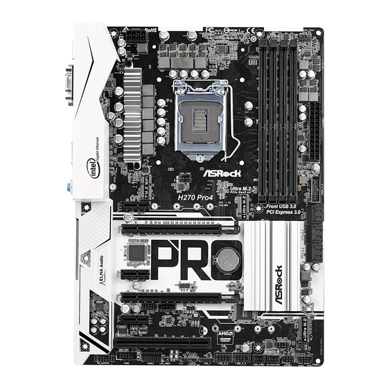
ASROCK H270 Pro4 Bedienungsanleitung
Inhaltsverzeichnis
Verfügbare Sprachen
Verfügbare Sprachen
Version 1.0
Published November 2016
Copyright©2016 ASRock INC. All rights reserved.
Copyright Notice:
No part of this documentation may be reproduced, transcribed, transmitted, or
translated in any language, in any form or by any means, except duplication of
documentation by the purchaser for backup purpose, without written consent of
ASRock Inc.
Products and corporate names appearing in this documentation may or may not
be registered trademarks or copyrights of their respective companies, and are used
only for identification or explanation and to the owners' benefit, without intent to
infringe.
Disclaimer:
Specifications and information contained in this documentation are furnished for
informational use only and subject to change without notice, and should not be
constructed as a commitment by ASRock. ASRock assumes no responsibility for
any errors or omissions that may appear in this documentation.
With respect to the contents of this documentation, ASRock does not provide
warranty of any kind, either expressed or implied, including but not limited to
the implied warranties or conditions of merchantability or fitness for a particular
purpose.
In no event shall ASRock, its directors, officers, employees, or agents be liable for
any indirect, special, incidental, or consequential damages (including damages for
loss of profits, loss of business, loss of data, interruption of business and the like),
even if ASRock has been advised of the possibility of such damages arising from any
defect or error in the documentation or product.
This device complies with Part 15 of the FCC Rules. Operation is subject to the following
two conditions:
(1) this device may not cause harmful interference, and
(2) this device must accept any interference received, including interference that
may cause undesired operation.
CALIFORNIA, USA ONLY
The Lithium battery adopted on this motherboard contains Perchlorate, a toxic substance
controlled in Perchlorate Best Management Practices (BMP) regulations passed by the
California Legislature. When you discard the Lithium battery in California, USA, please
follow the related regulations in advance.
"Perchlorate Material-special handling may apply, see www.dtsc.ca.gov/hazardouswaste/
perchlorate"
ASRock Website: http://www.asrock.com
Inhaltsverzeichnis

Verwandte Anleitungen für ASROCK H270 Pro4


Inhaltszusammenfassung für ASROCK H270 Pro4
- Seite 15 H270 Pro4...
- Seite 19 H270 Pro4...
- Seite 30 Kapitel 1 Einleitung Vielen Dank, dass Sie sich für das H270 Pro4 von ASRock entschieden haben – ein zuverlässiges Motherboard, das konsequent unter der strengen Qualitätskontrolle von ASRock hergestellt wurde. Es liefert ausgezeichnete Leistung mit robustem Design, das ASRock Streben nach Qualität und Beständigkeit erfüllt.
-
Seite 31: Technische Daten
H270 Pro4 1.2 Technische Daten Plattform • ATX-Formfaktor Prozessor • Unterstützt Intel®-Core -i7/i5/i3/Pentium®/Celeron®- Prozessoren der 7. und 6. Generation (Sockeö 1151) • Digi Power design • 8-Leistungsphasendesign • Unterstützt Intel® Turbo Boost 2.0-Technologie ® Chipsatz • Intel H270 Speicher • Dualkanal-DDR4-Speichertechnologie • 4 x DDR4-DIMM-Steckplätze... - Seite 32 DVI-D- und HDMI-Ports Audio • 7.1-Kanal-HD-Audio mit Inhaltsschutz (Realtek ALC892- Audiocodec) * Zur Konfiguration von 7.1-Kanal-HD-Audio müssen Sie ein HD-Frontblenden-Audiomodul nutzen und den Mehrkanalton über den Audiotreiber aktivieren. • Erstklassige Blu-ray-Audiounterstützung • Unterstützt Überspannungsschutz (ASRock Full Spike Protection) • ELNA-Audiokondensatoren...
- Seite 33 • 1 x DVI-D-Port • 1 x HDMI-Port • 5 x USB 3.0-Typ-A-Ports (unterstützt Schutz gegen elektrostatische Entladung (ASRock Full Spike Protection)) • 1 x USB 3.0-Typ-C-Port (unterstützt Schutz gegen elektrostatische Entladung (ASRock Full Spike Protection)) • 1 x RJ-45-LAN-Port mit LED (Aktivität/Verbindung-LED und Geschwindigkeit-LED) • HD-Audioanschlüsse: Line-in / Vorderer Lautsprecher /...
- Seite 34 • 1 x Thunderbolt Erweiterungskartenanschluss (10-polig) * Es wird nur eine Thunderbolt-AIC-Karte unterstützt. • 3 x USB-2.0-Stiftleiste (unterstützen 5 USB-2.0-Ports) (unter- stützt Schutz gegen elektrostatische Entladung (ASRock Full Spike Protection)) • 1 x USB-3.0-Stiftleiste (unterstützt 2 USB-3.0-Ports) (unter- stützt Schutz gegen elektrostatische Entladung (ASRock Full...
- Seite 35 • FCC, CE, WHQL, RCM, BSMI • ErP/EuP ready (ErP/EuP ready-Netzteil erforderlich) zierungen * Detaillierte Produktinformationen finden Sie auf unserer Webseite: http://www.asrock.com Bitte beachten Sie, dass mit einer Übertaktung, zu der die Anpassung von BIOS- Einstellungen, die Anwendung der Untied Overclocking Technology oder die Nutzung von Übertaktungswerkzeugen von Drittanbietern zählen, bestimmte Risiken verbunden...
-
Seite 36: Jumpereinstellung
1.3 Jumpereinstellung Die Abbildung zeigt, wie die Jumper eingestellt werden. Wenn die Jumper-Kappe auf den Kontakten angebracht ist, ist der Jumper „kurzgeschlossen“. Wenn keine Jumper- Kappe auf den Kontakten angebracht ist, ist der Jumper „offen“. Die Abbildung zeigt einen 3-poligen Jumper, dessen Kontakt 1 und Kontakt 2 „kurzgeschlossen“ sind, wenn eine Jumper-Kappe auf diesen 2 Kontakten angebracht ist. -
Seite 37: Integrierte Stiftleisten Und Anschlüsse
H270 Pro4 1.4 Integrierte Stiftleisten und Anschlüsse Integrierte Stiftleisten und Anschlüsse sind KEINE Jumper. Bringen Sie KEINE Jumper- Kappen an diesen Stiftleisten und Anschlüssen an. Durch Anbringen von Jumper-Kappen an diesen Stiftleisten und Anschlüssen können Sie das Motherboard dauerhaft beschädi- gen. - Seite 38 Betrieb-LED- und Bitte verbinden Sie SPEAKER DUMMY die Betrieb-LED des Lautsprecher-Stiftleiste DUMMY Gehäuses und den (7-polig, SPK_PLED1) Gehäuselautsprecher (siehe S. 1, Nr. 15) mit dieser Stiftleiste. PLED+ PLED+ PLED- Serial-ATA-III-Anschlüsse Diese sechs SATA-III- Anschlüsse unterstützen (SATA3_0: SATA-Datenkabel für siehe S. 1, Nr. 13) interne Speichergeräte (SATA3_1: mit einer Datenübertrag...
- Seite 39 H270 Pro4 USB 3.0-Stiftleiste Neben sechs USB Vbus Vbus 3.0-Ports an der E/ (19-polig, USB3_3_4) Vbus IntA_PB_SSRX- IntA_PA_SSRX- IntA_PB_SSRX+ A-Blende befindet sich IntA_PA_SSRX+ (siehe S. 1, Nr. 7) IntA_PB_SSTX- eine Stiftleiste an diesem IntA_PA_SSTX- IntA_PB_SSTX+ IntA_PA_SSTX+ Motherboard. Jede USB IntA_PB_D-...
- Seite 40 Anschluss für Gehäuselüfter / Bitte verbinden Sie die Lüfterkabel mit den Wasserpumpenlüfter Lüfteranschlüssen; der FAN_SPEED_CONTROL (4-polig, CHA_FAN3/W_ CHA_FAN_SPEED schwarze Draht gehört PUMP) FAN_VOLTAGE zum Erdungskontakt. (siehe S. 1, Nr. 16) CPU-Lüfteranschluss Dieses Motherboard FAN_VOLTAGE CPU_FAN_SPEED bietet einen 4-poligen (4-polig, CPU_FAN1) FAN_SPEED_CONTROL CPU-Lüfteranschluss (siehe S.
- Seite 41 H270 Pro4 Gehäuseeingriff-Stiftleiste Dieses Motherboard unterstützt die Gehäuse- (2-polig, CI1) Signal offen-Erkennung, die (siehe S. 1, Nr. 22) erkennt, wenn die Gehäuseabdeckung entfernt wurde. Diese Funktion setzt ein Gehäuse mit Gehäusee- ingrifferkennungsdesign voraus. TPM-Stiftleiste Dieser Anschluss unter- stützt das Trusted Plat-...