Inhaltsverzeichnis
Werbung
Verfügbare Sprachen
Verfügbare Sprachen
Quicklinks
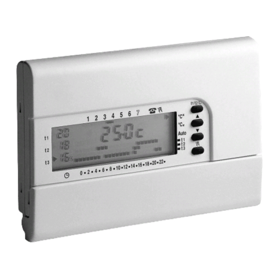
CRONOTERMOSTATO DIGITALE DA PARETE
WALL MOUNTING DIGITAL CHRONOTHERMOSTAT
CHRONOTHERMOSTAT DIGITAL POUR MONTAGE EN SAILLIE
DIGITAL RAUMTHERMOSTATUHR WANDMONTAGE
CRONOTERMOSTATO DIGITAL DE SUPERFICIE
PE - DECRNN029
02/10 (mask 1)
Easy Program
Giornaliero - Settimanale, Inverno / Estate
3 livelli di temperatura + antigelo
Ingresso per programmatore telefonico
Daily - Weekly, Winter / Summer
3 temperature levels + antifreeze
Telephone programmer input
Journalier - Hebdomandaire, Hiver / Eté
3 niveaux de température + antigel
Entrée par télécommande téléphonique
Täglich - Wöchentlich, Winter / Sommer
3 Temperaturstufen + Frostschutz
mit Eingang für Telefonschaltung
Día - Semanal, Invierno / Verano
3 niveles de temperatura + antihielo
Entrada para comando telefónico
Werbung
Inhaltsverzeichnis

Verwandte Anleitungen für Perry Electric Easy Program

Inhaltszusammenfassung für Perry Electric Easy Program
- Seite 1 3 niveaux de température + antigel Entrée par télécommande téléphonique Täglich - Wöchentlich, Winter / Sommer 3 Temperaturstufen + Frostschutz mit Eingang für Telefonschaltung Easy Program Día - Semanal, Invierno / Verano 3 niveles de temperatura + antihielo PE - DECRNN029 02/10 (mask 1)
- Seite 2 ITALIANO struzioni per l’installazione, programmazione e modo di impiego: pag. 3 ENGLISH - Instructions to install, program and use the device: pag. 24 FRANCAIS - Instructions pour l'installation, la programmation et le mode d'emploi: pag. 45 DEUTSCH - Installations-, Programmierungs- und Bedienungsanleitung: Seite 66 ESPANOL - Instrucciones de instalación, programación y modo de empleo: pág.
- Seite 3 INDICE ITALIANO 1 - DATI TECNICI pag. 4 6 - FUNZIONI RISPARMIO ENERGETICO pag. 17 2 - INSTALLAZIONE pag. 5 7 - FUNZIONI PROGRAMMABILI DI pag. 21 ADATTAMENTO AL TIPO DI IMPIANTO 3 - LEGENDA INDICAZIONE DISPLAY pag. 8 pag. 23 8 - ATTIVAZIONE DA PROGRAMMATORE pag.
- Seite 4 1 - DATI TECNICI Alimentazione: n. 2 pile alcaline Ministilo 1,5 V - mod. LR03 (AAA) 1,5 V 1050 mA/h consigliate pile DURACELL o ENERGIZER Autonomia di funzionamento: 12 mesi circa Autonomia dall’accensione sul display del simbolo di “Batteria scarica”: 1 mese circa Tipo di azione, disconnessione e apparecchio: 1 / B / U / Elettronico...
-
Seite 5: Esempi D'installazione
2 - INSTALLAZIONE 2.1 - AVVERTENZE! Fig. 1 • Leggere attentamente il libretto istruzioni prima di utilizzare il prodotto in quanto fornisce importanti indicazioni riguardanti la sicurezza, l’installazione e h 1,5 m l’uso. Conservare con cura il libretto istruzioni per successive consultazioni. •... - Seite 6 2.3 - Installazione del cronotermostato •Disattivare la tensione del dispositivo da comandare. •Fissare la base del cronotermostato alla scatola incasso (o alla parete), utilizzando le opportune coppie di fori (fig. 5): per scatola tonda (diametro 60 mm) con griffe per scatola tonda o quadra con viti per scatola rettangolare (3 posti) con viti N.B.
-
Seite 7: Collegamenti Elettrici
2.4 - Collegamenti elettrici Disattivare la tensione di rete del dispositivo da comandare. Collegare i fili del dispositivo da comandare alla morsettiera posta sulla Fig. 8 parte posteriore del corpo del cronotermostato (fig. 8 o 9). Collegamento Morsetto n° comune ad una caldaia Morsetto n°... - Seite 8 3 - LEGENDA INDICAZIONI DISPLAY Fig. 11 Indice segnalazione temperatura di riferimento Visualizzazione temperatura di Set impostata (a step di 0,5 °C) Segnalazione utenza allacciata in funzione (es. Caldaia) Giorni della settimana (es. 3 = Mercoledì) Ora attuale o temperatura ambiente Funzionamento attivato con programmatore telefonico Funzionamento manuale Funzionamento in INVERNO...
- Seite 9 4 - LEGENDA FUNZIONI TASTI Tasto per conferma (ore, minuti, giorno, programma e per tutte le operazioni dove è richiesta la conferma) Fig. 12 Tasto selezione - visualizzazione programmi P 01 ÷ P 06 Tasto accesso alla modifica: ora - minuti - giorno correnti / Tasto visualizzazione ora o temperatura ambiente Tasto per lettura ore di funzionamento impianto 5) Tasto sospensione programma in corso per pulizie ambientali...
- Seite 10 5 - PROGRAMMAZIONE Lampeggianti IMPORTANTE: tutte le impostazioni effettuate devono essere confermate premendo il tasto OK, in caso contrario, trascorsi 2 minuti il cronotermosta- to torna al normale funzionamento e le modifiche non saranno conservate. Fig. 13 All'inserimento delle pile o dopo un’operazione di Reset (RESET premere contemporanea- mente per 2 sec.
- Seite 11 5.2 - Programma libero P 05 Il programma P 05 è liberamente programmabile per ogni ora del giorno su quattro Fig. 16 differenti livelli di temperatura ( t1, t2, t3, t ) ed in modo diverso per ogni giorno della settimana.
- Seite 12 La conferma ( in fig.18) fisserà in memoria il programma impostato (per Lunedì) e sul martedì display apparirà lampeggiante il trattino sotto il giorno di Martedì 2 ( ) e lampeggianti i digit in corrispondenza dell'ora 0:00 , sovrapposti alla scala termica programmata per il giorno precedente (fig.
- Seite 13 5.3 - Programmazione della mezz'ora (½ h) Fig. A Fig. B 1° 2° Esempio, in prima impostazione P05, per programmare: - dalle ore 06:00 alle ore 06:30 funzionamento con temperatura (economy) - dalle ore 06:30 alle ore 07:00 funzionamento con temperatura (comfort) 1°...
- Seite 14 5.5 - Programmazione ESTATE - INVERNO Fig. 24 Inverno Estate II Vostro cronotermostato viene predisposto in fabbrica per il funzionamento "Inverno" visualizzato da: Il funzionamento dell’utenza verrà segnalato dalla scritta In tali condizioni verrà inserita I’utenza allacciata (caldaia) come da esempio sotto indicato: lampeggiante: ON Caldaia in funzione con: Esempio:...
- Seite 15 5.7 - Modifica delle temperature di Set: Comfort, Attività ed Economy Fig. 26 Nel caso le temperature prefissate: Indice del set di temperatura selezionato (lampeggiante) = 20,0 °C, = 18,0 °C, = 16,5 °C (per inverno) = 20,0 °C, = 22,0 °C, = 23,5 °C (per estate) non soddisfino le Vostre necessità, si potranno modificare a piacimento, da +5 °C a +39 °C, premendo i relativi tasti.
- Seite 16 5.9 - Lettura dei programmi inseriti Premere il tasto PROG : apparirà sul display il programma utilizzato come ad esempio in fig. 28. Nel caso il programma sia uno dei quattro programmi fissi inseriti ( P 01 ÷ P 04 ), verranno Fig.
- Seite 17 Lampeggiante 6 - FUNZIONI RISPARMIO ENERGETICO 6.1 - Limitazione dei valori di temperatura impostabili In alcuni casi particolari di installazione del cronotermostato, ad esempio in edifici pubblici, Fig. 31 alberghi ecc., potrebbe essere utile limitare il set di temperatura massimo e/o minimo in modo da evitare impostazioni errate da parte di personale non autorizzato.
- Seite 18 6.2 - Funzionamento in MANUALE - manuale temporaneo (indice lampeggiante) Sono possibili 2 modi di funzionamento manuale, con sospensione del programma in corso: a) Funzionamento manuale temporaneo. • Premere brevemente il tasto : appare l'indice lampeggiante , sotto il simbolo e il livello funz.
- Seite 19 6.4 - Programma HOLIDAY - P 06 Nel caso in cui ci si debba assentare per più giorni dalla propria abitazione selezionare il programma P 06 Holiday (Vacanze). Premere ripetutamente il tasto PROG sino a quando sul display apparirà la scritta P 06 quindi confermare premendo il tasto (fig.
- Seite 20 6.5 - Visualizzazione consumi attraverso il numero di ore di funzionamento dell'utenza Fig. 40 II cronotermostato calcola e mantiene in memoria le ore di funzionamento della caldaia (e/o condizionatore) durante le 24 ore del giorno precedente e dall’inizio della stagione (ore di funzionamento totali).
- Seite 21 6.7 - Segnalazione di non funzionamento dell’impianto (es.: blocco caldaia o condizionatore in avaria) Fig. 44 In Inverno: se durante il normale funzionamento (scritta lampeggiante) il cronotermostato non rileva, in un arco di tempo di 2 ore, un incremento significativo di temperatura, si attiva sul display la segnalazione di riscaldamento non funzionante hOFF (es.
- Seite 22 7.2 - Ciclo anticalcare Se la funzione è attivata, il relè del cronotermostato interviene tutti i giorni dell’anno alle ore 12:00, per la durata di 2 minuti primi, attivando il dispositivo comandato (pompa, valvola) allo scopo di evitare incrostazioni e grippaggi causati da inattività prolungata. N.B.
- Seite 23 8 - ATTIVAZIONE DA PROGRAMMATORE TELEFONICO 8.1 - Funzionamento con programmatore telefonico Il programmatore telefonico permette di comandare a distanza il cronotermostato agendo sul contatto collegato ai morsetti e di quest'ultimo (vedere paragrafo 2.4 - Collegamenti Esempio Programmatore telefonico elettrici). Funzionamento cronotermostato Programmatore telefonico in modalità...
- Seite 24 INDEX ENGLISH 1 - TECHNICAL SPECIFICATIONS pg. 25 6 - ENERGY SAVING FUNCTIONS pg. 38 2 - INSTALLATION pg. 26 7 - PROGRAMMABLE FUNCTIONS FOR pg. 42 DIFFERENT APPLIANCES 3 - DISPLAY LEGEND pg. 29 pg. 44 8 - ACTIVATION VIA TELEPHONE pg.
-
Seite 25: Technical Specifications
1 - TECHNICAL SPECIFICATIONS Power supply: alkaline batteries 1.5 V - mod. LR03 (AAA) 1.5 V 1050 mA/h DURACELL or ENERGIZER batteries are recommended Autonomous operation time: approx. 12 months Time remaining from when “Battery Low” symbol appears: approx. 1 month Type of action, disconnection and device: 1 / B / U / Electronic Type of output:... -
Seite 26: Examples Of Installation
2 - INSTALLATION 2.1 - CAUTION! Fig. 1 • Carefully read the instruction manual before using the product as it provides important guidelines regarding safety, installation and use. The instruction h 1,5 m manual must be preserved with care for future reference. •... - Seite 27 2.3 - Chronothermostat installation •Disconnect the power supply from the device •Fasten the base of the chronothermostat to the recessed box (or to the wall) via the paired holes (fig. 5): for a round box (60 mm diameter) with clips for a round or square box with screws for a rectangular box (3 places) with screws N.B.
-
Seite 28: Electrical Connections
2.4 - Electrical connections Disconnect the power supply from the device. Connect the wires of the device that is to be controlled to the terminal Fig. 8 block on the back part of the chronothermostat body (fig. 8 or 9). Connected Terminal No. - Seite 29 3 - DISPLAY INDICATORS LEGEND Fig. 11 Reference temperature indicator Displays the set temperature (in grades of 0.5 °C) Connected device is on (e.g. Boiler) Days of the week (e.g. 3 = Wednesday) Current time or temperature Activated via telephone programmer Manual mode WINTER mode (heating)
- Seite 30 4 - KEY FUNCTION LEGEND 1) OK button to confirm (hour, minutes, day, program and all operations that require confirmation) Fig. 12 Button to select/display programs P 01 to P 06 Button to change: current hour - minutes - day / Button to display time or room temperature Button to display hours of operation 5) Button to suspend the current program to implement cleaning...
- Seite 31 5 - PROGRAMMING Blinking IMPORTANT: all settings must be confirmed by pressing OK, otherwise the chronothermostat returns to the previous settings after 2 minutes and any changes made will not be saved. Fig. 13 After inserting the batteries or after resetting (RESET: press simultaneously for 2 seconds) all sections that are on will appear on the display, after which, the blinking digits relative to the hour and minutes will appear, as shown in figure 13.
- Seite 32 5.2 - Customized program P 05 Program P 05 can be programmed for every hour of the day at four different Fig. 16 temperatures ( t1, t2, t3, t ) and differently for every day of the week. P 05 Press PROG until...
- Seite 33 When is pressed (fig. 18) to confirm, the program set for Monday is saved in the memory and the dash beneath Tuesday 2 ( ) will blink together with the digits pertaining to the time 0:00 , above the temperature range for the previous day (fig. 19). Setting the temperatures for Tuesday.
- Seite 34 5.3 - Programming half-hours (½ h) Fig. A Fig. B 1° 2° For example, P05 setting, to program: - from h 06:00 to h 06:30 with (economy) temperature - from h 06:30 to h 07:00 with (comfort) temperature 1° Set temperature t3 at h 06:00: press until the three blinking digits are set an hour later Time: 06:00...
- Seite 35 5.5 - SUMMER -WINTER programs Fig. 24 Winter Summer Your chronothermostat is factory-set as “Winter” and displayed as: In these conditions, the device (boiler) will be connected as described in the example below: Functionality of the device is confirmed when blinks.
- Seite 36 5.7 - Changing the temperature settings: Comfort, Working and Economy Fig. 26 If the factory-set temperatures: Selected temperature setting indicator (blinking) = 20,0 °C, = 18,0 °C, = 16,5 °C (for winter) = 20,0 °C, = 22,0 °C, = 23,5 °C (for summer) do not happen to be suitable, they can be changed accordingly from +5 °C to +39 °C, by pressing the relative buttons.
- Seite 37 5.9 - Reading the programs Press PROG: the program in use will appear on the display as shown in the example (Fig. 28). If the program is one of the four fixed programs ( P 01 P 04 ), the settings per day will appear automatically on the display one after the other (Fig.
- Seite 38 6 - ENERGY SAVING FUNCTIONS Blinking 6.1 - Limiting the temperature setting values In some particular installations, for instance in public offices, hotels, etc., it may be useful to limit Fig. 31 the maximum and/or minimum temperature settings to avoid incorrect settings being entered by unauthorised personnel.
- Seite 39 6.2 - MANUAL mode - Temporary manual mode (blinking indicator) There are 2 manual modes. While the current program is stopped: a) Temporary manual operation. • Briefly press and the indicator will blink beneath and the current temperature level will manual Fig.
- Seite 40 6.4 - HOLIDAY Program - P 06 If you will be away from home for a few days select P 06 Holiday Press PROG repeatedly until P 06 , appears on the display, then press to confirm (fig. 37). The following will appear on the display: the day of the week, the symbol , the word Fig.
- Seite 41 6.5 - Displaying consumption via the number of operating hours Fig. 40 The chronothermostat calculates and memorises the hours of operating of the boiler (and/or air conditioner) during the 24 hours of the previous day and from the start of the season (total hours of operating).
- Seite 42 6.7 - System troubleshooting indicator (e.g.: Blocked boiler or air-conditioner is malfunctioning) In Winter: if during normal operation ( indicator blinks), the chronothermostat does Fig. 44 not detect a significant increase in temperature within 2 hours, the display will indicate that the heating system is not working hOFF (e.g.
- Seite 43 7.2 - Anti-scale cycle When this function is selected, the chronothermostat relay will intervene every day at 12:00 and activate the connected device (pump, valve) for 2 minutes in order to prevent scale from forming and prevent seizure that could be caused by prolonged inactivity. N.B.
- Seite 44 8 - ACTIVATION VIA TELEPHONE PROGRAMMER 8.1 - Telephone programmer operating mode The telephone programmer allows you to control the chronothermostat from a distance via the contact connected to terminals di quest'ultimo (see paragraph 2.4 - Electrical Example Telephone programmer connections).
- Seite 45 INDEX FRANÇAIS 1 - DONNÉES TECHNIQUES page 46 6 - FONCTIONS POUR L'ÉCONOMIE D'ÉNERGIE page 59 2 - INSTALLATION page 47 7 - FONCTIONS PROGRAMMABLES page 63 D'ADAPTATION AU TYPE D'INSTALLATION 3 - LÉGENDE AFFICHEUR page 50 Page 65 8 - ACTIVATION PAR TÉLÉCOMMANDE page 51 4 - LÉGENDE FONCTION DES TOUCHES TÉLÉPHONIQUE...
-
Seite 46: Données Techniques
1 - DONNÉES TECHNIQUES Alimentation : n. 2 piles alcalines Ministilo 1,5 V - mod. LR03 (AAA) 1,5 V 1050 mA/h piles conseillées DURACELL ou ENERGIZER Autonomie : 12 mois environ Autonomie de l'allumage sur l'afficheur du symbole “Batterie déchargée” : 1 mois environ Type d'action, déconnexion et appareil : 1 / B / U / Electronique... -
Seite 47: Avertissements
2 - INSTALLATION 2.1 - AVERTISSEMENTS! Fig. 1 • Lire attentivement le présent livret d'instructions avant d'utiliser le produit car il fournit d'importantes indications concernant la sécurité, l'installation et l'emploi de ce h 1,5 m dernier. Conserver soigneusement le livret d'instructions pour toute consultation ultérieure. - Seite 48 2.3 - Installation du chronothermostat •Désactiver la tension du réseau du dispositif à piloter. •Fixer la base du chronothermostat au boîtier à encastrer (ou au mur), en utilisant les paires de trous adéquates (fig. 5) : pour boîtier rond (diamètre 60 mm) avec crochets pour boîtier rond ou carré...
-
Seite 49: Branchements Électriques
2.4 - Branchements électriques Désactiver la tension de réseau du dispositif à piloter. Raccorder les fils du dispositif à piloter à la plaque à bornes située à Fig. 8 l'arrière du corps du chronothermostat (fig. 8 ou 9). Branchement Borne n° commun à... - Seite 50 3 - LÉGENDE AFFICHEUR Fig. 11 Indication température réglée Affichage température de Set configurée (par variations de 0,5 °C) Signal appareil branché en marche (ex. chaudière) Jours de la semaine (ex. 3 = Mercredi) Heure actuelle ou température ambiante Fonctionnement activé avec télécommande téléphonique Fonctionnement manuel Fonctionnement en HIVER (chauffage)
- Seite 51 4 - LÉGENDE FONCTION DES TOUCHES Touche de confirmation (heures, minutes, jour, programme et pour toutes les opérations où une confirmation est demandée) Fig. 12 Touche de sélection - affichage programmes P 01 ÷ P 06 Touche d'accès pour modifier : heure - minutes - jour actuel / Touche affichage heure ou température ambiante Touche de lecture des heures de fonctionnement 5) Touche de suspension du programme pour nettoyage...
- Seite 52 5 - PROGRAMMATION Clignotants IMPORTANT : Toutes les configurations effectuées doivent être confirmées en appuyant sur la touche OK, dans le cas contraire, 2 minutes plus tard le chronothermostat revient à son fonctionnement normal et les modifications ne seront pas conservées. Fig.
- Seite 53 5.2 - Programme libre P 05 Le programme P 05 se programme librement pour chaque heure du jour sur quatre Fig. 16 niveaux de température ( t1, t2, t3, t ) et de façon différente pour chaque jour de la semaine.
- Seite 54 La confirmation ( permet de mémoriser le programme configuré pour Lundi - fig. 18 ) Mardi et l'afficheur fait clignoter un tiret sous le Mardi 2 ( )et les digits au niveau de l'heure 0:00 superposés à l'échelle thermique programmée pour la veille (fig. 19). Programmation température pour le Mardi.
- Seite 55 5.3 - Programmation de la demi-heure (½ h) Fig. A Fig. B 1° 2° Exemple, dans la première configuration P05, pour programmer : - de h 06 :00 à h 06:30 fonctionnement avec température (économie) - de h 06:30 à h 07:00 fonctionnement avec température (confort) 1°...
- Seite 56 5.5 - Programmation ÉTÉ - HIVER Fig. 24 Hiver Été En usine, votre chronothermostat a été configuré pour fonctionner en mode "Hiver” visualisé sur l'afficheur par : Le fonctionnement de Dans ces conditions, l'appareil raccordé (chaudière) sera activé comme dans l'exemple : l'appareil sera signalé...
- Seite 57 5.7 - Modification des températures : Confort, Activité et Économie Fig. 26 Si les températures préétablies: Plage de température sélectionnée (clignotante) = 20,0 °C, = 18,0 °C, = 16,5 °C (hiver) = 20,0 °C, = 22,0 °C, = 23,5 °C (été) ne répondent pas à...
- Seite 58 5.9 - Lecture des programmes saisis Appuyer sur la touche PROG : le programme utilisé apparaît sur l'afficheur comme par exemple dans la Fig. 28. Si le programme est l'un des quatre programmes fixes saisis ( P 01 ÷ P 04 ), les réglages sont Fig.
- Seite 59 6 - FONCTIONS POUR L'ÉCONOMIE D'ÉNERGIE Clignotante 6.1 - Limitation des valeurs de température programmables Dans certains cas particuliers d'installation du chronothermostat, par exemple dans des bâtiments publics, des hôtels etc., il pourrait s'avérer utile de limiter le réglage de la température Fig.
-
Seite 60: Fonctionnement Manuel
6.2 - Fonctionnement MANUEL - manuel temporaire (flèche clignotante) Il existe deux modes de fonctionnement manuel, avec suspension du programme en cours : a) Fonctionnement manuel temporaire. • Appuyer rapidement sur la touche : la flèche , apparaît en clignotant, sous le symbole manuel Fig. - Seite 61 6.4 - Programme HOLIDAY - P 06 Dans les cas où vous devriez vous absenter de la maison pendant plusieurs jours, sélectionner le programme P 06 Holiday (Vacances). Appuyer plusieurs fois sur la touche PROG jusqu'à ce qu'à l'écran apparaisse l'indication P 06 , puis confirmer en appuyant sur la touche...
- Seite 62 6.5 - Affichage de la consommation à travers le nombre d'heures de fonctionnement de l'appareil Le chronothermostat calcule et garde en mémoire les heures de fonctionnement de la Fig. 40 chaudière (et/ou du climatiseur) pendant les 24 heures de la veille et depuis le début de la saison (heures totales de fonctionnement).
- Seite 63 6.7 - Signal de non-fonctionnement de l'installation (ex.: Blocage chaudière ou climatiseur en panne) En Hiver : si, pendant le fonctionnement normal (indice clignotant), le Fig. 44 chronothermostat ne détecte pas d'incrément significatif de la température dans les 2 heures qui suivent, l'afficheur présente le signal qui indique que le chauffage ne fonctionne pas hOFF (ex.
-
Seite 64: Cycle Anticalcaire
7.2 - Cycle anticalcaire Si la fonction est activée, le relais du chronothermostat intervient tous les jours de l'année à 12:00, pendant 2 minutes, ce qui provoque l'activation du dispositif commandé (pompe, valve) de façon à éviter toute incrustation ou tout grippage dû à un arrêt prolongé (fig. 48). Remarque : dans la configuration d'usine cette fonction est désactivée. - Seite 65 8 - FONCTIONNEMENT PAR TÉLÉCOMMANDE TÉLÉPHONIQUE 8.1 - Fonctionnement par télécommande téléphonique La télécommande téléphonique permet de commander à distance le chronothermostat en agissant sur le contact relié aux bornes de ce dernier (voir paragraphe 2.4 Exemple Télécommande téléphonique Branchements électriques). Fonctionnement chronothermostat Télécommande téléphonique en mode manuel permanent...
-
Seite 66: Inhaltsverzeichnis
INHALT DEUTSCH 6 - FUNKTIONEN GERINGER S. 80 1 - TECHNISCHE DATEN S. 67 ENERGIEVERBRAUCH 2 - INSTALLATION S. 68 S. 84 7 - PROGRAMMIERBARE FUNKTIONEN ZUR 3 - LEGENDE DISPLAYANZEIGEN S. 71 ANPASSUNG AN DIE ANLAGENART 4 - LEGENDE TASTENFUNKTIONEN S. -
Seite 67: Technische Daten
1 - TECHNISCHE DATEN Versorgungsspannung: Nr. 2 Alkali- Batterien Mignon 1,5 V - Mod. LR03 (AAA) 1,5 V 1050 mA/h empfohlen werden DURACELL oder ENERGIZER Betriebsdauer: etwa 12 Monate Betriebsdauer nach Einschalten auf Display "Batterie entladen": etwa 1 Monat Anschlussart, Gerätetyp: 1 / B / U / Elektronisch Ausgang: Relais mit unipolarem Wechselkontakt potentialfrei... -
Seite 68: Installation
2 - INSTALLATION 2.1 -HINWEISE! Abb. 1 • Lesen Sie die Gebrauchsanweisung aufmerksam durch, bevor Sie das Produkt anwenden. Sie finden hierin alle wissenswerten Angaben zu Sicherheit, Installation und h 1,5 m Gebrauch. Bewahren Sie die Gebrauchsanweisung für spätere Zwecke sorgfältig auf. •... -
Seite 69: Installation Der Raumthermostatuhr
2.3 - Installation der Raumthermostatuhr • Die Netzspannung von dem zu steuernden Gerät abschalten. •Die Grundplatte der Raumthermostatuhr am Unterputzgehäuse (oder an der Wand) befestigen. Dazu die zwei passenden Bohrungen (Abb. 5) verwenden für rundes Unterputzgehäuse (Durchmesser 60 mm) mit Verschlusshaken für rundes oder quadratisches Unterputzgehäuse mit Schrauben für rechteckiges Unterputzgehäuse (3 Plätze) mit Schrauben Beachte... -
Seite 70: Elektrische Anschlüsse
2.4 - Elektrische Anschlüsse Schalten Sie die Netzspannung von dem zu steuernden Gerät ab. Die Kabel des zu steuernden Gerätes an die Klemmenleiste am Abb. 8 rückwärtigen Gehäuseteil der Raumthermostatuhr anschließen Anschluss an einen (Abb. 8 oder 9). Durchlauferhitzer Klemme Nr. gemeinsam Klemme Nr. -
Seite 71: Legende Displayanzeigen
3 - LEGENDE DISPLAYANZEIGEN Abb. 11 Anzeige der Bezugstemperaturmeldung Anzeige der eingestellten Temperaturprogrammierung (in Schritten Von 0,5 °C) Meldung der in Betrieb befindlichen angeschlossenen Geräte (z.B. Durchlauferhitzer) Wochentage (z.B. 3 = Mittwoch) Aktuelle Uhrzeit oder Raumtemperatur Betriebsmodus über Telefonschaltung aktiviert Manueller Betriebsmodus Betriebsmodus im WINTER (Heizung) -
Seite 72: Legende Tastenfunktionen
4 - LEGENDE TASTENFUNKTIONEN Die Bestätigungstaste (Stunden, Minuten, Tag, Programm und für alle Tätigkeiten, die bestätigt werden müssen) Abb. 12 Wähltaste - Anzeige der Programme P 01 ÷ P 06 Taste zum Ändern von: Stunde - Minuten - Wochentag / Abruftaste Uhrzeit oder Raumtemperatur Taste zur Anzeige der Betriebsstunden der Anlage Taste zur Unterbrechung des aktuellen Programms, für Reinigungsarbeiten... -
Seite 73: Programmierung
5 - PROGRAMMIERUNG Blinkend WICHTIG: Alle vorgenommenen Einstellungen müssen mit der OK-Taste bestätigt werden, anderenfalls kehrt das Thermostat nach 2 Minuten zum Normalbetrieb zurück und die Änderungen gehen verloren. Abb. 13 Bei Einsatz der Batterien oder nach einem Reset (RESET gleichzeitig 2 Sek. lang die Tasten drücken ) auf dem Display erscheinen alle aktiven Segmente und anschließend blinken die Ziffern der Stunden und Minutenanzeige, wie in Abbildung 13 dargestellt. - Seite 74 5.2 - Freies Programm P 05 Das Programm P 05 ist für jede Tageszeit auf vier unterschiedlichen Temperaturstufen Abb. 16 t1, t2, t3, t ) auf unterschiedliche Weise jeden Wochentag frei programmierbar. P 05 Betätigen Sie die Taste PROG bis auf der Anzeige der Schriftzug .
- Seite 75 Durch die Bestätigung ( in Abb.18) wird das eingegebene Programm (Montag) Dienstag gespeichert und auf der Anzeige blinken der Strich unter Dienstag 2 ( ) und die Ziffern, die sich auf die entsprechende Zeitangabe 0:00 beziehen auf. Darüber wird die Temperaturskala des vorhergehenden Tages wiedergegeben (Abb.
-
Seite 76: Programmierung Einer Halben Stunde (½ Std)
5.3 - Programmierung einer halben Stunde (½ Std) Abb. A Abb. B 1° 2° Beispiel für die Einstellung des Programms P05: - von 06:00 Uhr bis 06:30 Uhr Betrieb mit der Temperatur (economy) - von 06:30 Uhr bis 07:00 Uhr Betrieb mit der Temperatur (komfort) 1°... -
Seite 77: Programmierung Sommer
5.5 - Programmierung SOMMER - WINTER Abb. 24 Winter Sommer Ihre Raumthermostatuhr wird werkseitig auf den Betriebsmodus "Winter” eingestellt, was Folgendermaßen angezeigt wird: Unter diesen Bedingungen wird die angeschlossene Der Betrieb der Anwendung Anlage (Durchlauferhitzer) gemäß dem nachfolgenden Beispiel eingerichtet wird durch den blinkenden Durchlauferhitzer in Betrieb bei: Schriftzug angezeigt: ON... - Seite 78 5.7-VeränderungderTemperatureinstellungen:Komfort,AktivundEconomy Abb. 26 Sofern die vorgegebenen Temperaturen: Anzeige der ausgewählten (blinkend) Temperatureinstellung = 20,0 °C, = 18,0 °C, = 16,5 °C (für den Winter) = 20,0 °C, = 22,0 °C, = 23,5 °C (für den Winter)nicht Ihren persönlichen Bedürfnissen entsprechen, können diese beliebig geändert werden (zwischen +5 °C und +39 °C), indem die entsprechenden Tasten gedrückt werden.
-
Seite 79: Anzeige Der Eingegebenen Programme
5.9 - Anzeige der eingegebenen Programme Betätigen Sie die Taste PROG : auf Display erscheint das angewandte Programm, wie in Abb. 28 beispielhaft dargestellt. Stimmt dieses mit einem der feststehenden Programme überein ( P 01 ÷ P 04 ) werden in Abb. -
Seite 80: Funktionen Geringer Energieverbrauch
Blinkend 6 - FUNKTIONEN GERINGER ENERGIEVERBRAUCH 6.1 - Begrenzungen für die einzugebenden Temperaturwerte In einigen besonderen Fällen der Installation der Raumthermostatuhr, zum Beispiel in öffentlichen Abb. 31 Gebäuden, Hotels, etc., kann es nützlich sein, die Einstellung der Höchst- oder Mindesttemperatur zu begrenzen, um falsche Einstellungen durch nicht autorisiertes Personal zu verhindern. -
Seite 81: Manueller Betriebsmodus
6.2 - MANUELLER Betriebsmodus - vorübergehend manuell (Blinkende Anzeige) Es stehen 2 manuelle Betriebsmodi zur Verfügung, durch die das aktuelle Programm unterbrochen wird: A) vorübergehender manueller Betriebsmodus. manuell Abb. 34 • Drücken Sie kurz die Taste : es erscheint die blinkende Anzeige unter dem Symbol und die aktive Temperaturstufe wird auf die verbleibenden Stunden des Tages angewendet (Abb. - Seite 82 6.4 - Programm HOLIDAY - P 06 Sollten Sie einmal für mehrere Tage nicht zuhause sein, wählen Sie das Programm P 06 Holiday (Urlaub). Drücken Sie wiederholt die Taste PROG bis auf dem Display der Schriftzug P 06 erscheint, dann durch Drücken der Taste (Abb.
-
Seite 83: Abschaltung Der Raumthermostatuhr (Off)
6.5 - Verbrauchsanzeige mittels Wiedergabe der Betriebsstunden der Anlage Die Raumthermostatuhr speichert die Betriebsstundenanzahl des Durchlauferhitzers (bzw. Abb. 40 der Klimaanlage) während der 24 Stunden des vorherigen Tages sowie seit Beginn der Heizperiode (gesamte Betriebsstundenanzahl). Diese Daten werden zur Bestimmung (indikativ) des Energieverbrauchs der Anlage benötigt. -
Seite 84: Anzeige Anlage Nicht In Betrieb
6.7 - Anzeige Anlage nicht in Betrieb (Beisp.: Blockierung des Durchlauferhitzers oder Klimaanlage beschädigt) Im Winter: wenn die Raumthermostatuhr während ihres normalen Betriebs (Anzeige Abb. 44 blinkend) in einem Zeitraum von 2 Stunden keinen bedeutenden Temperaturanstieg misst, erscheint auf Display das Symbol für Heizungsanlage nicht in Betrieb hOFF (z.B. -
Seite 85: Ausschalten Der Frostschutztemperatur
7.2 - Kalkschutz Durch die Aktivierung dieser Funktion betätigt das Relais der Raumthermostatuhr täglich um 12:00 Uhr 2 Minuten lang die gesteuerte Vorrichtung (Pumpe, Ventil), um eventuelles durch den Stillstand bedingtes Verkrusten bzw. Korrosion zu verhindern. Beachte : diese Funktion wird werkseitig im Zustand "Betrieb ausgeschaltet" eingestellt. Um diese Funktion zu programmieren, betätigen Sie die Taste , bis auf der Anzeige der Abb. -
Seite 86: Telefonschaltung Aktivieren
8 - TELEFONSCHALTUNG AKTIVIEREN 8.1 - Betriebsmodus über Telefonschaltung Der Betriebsmodus über Telefonschaltung gestattet es, die Raumthermostatuhr durch Betätigung des an den Klemmen angeschlossenen Kontaktes, fernzusteuern Beispiel Telefonschaltung (siehe Abschnitt 2.4 - Elektrische Anschlüsse). Betriebsmodus Raumthermostatuhr Telefonschaltung Im permanenten manuellem Modus Kontakt geschlossen mit Temperatur t1 Komfort Rückkehr zum zuvor eingestellten... - Seite 87 ÍNDICE ESPAÑOL 1 - DATOS TÉCNICOS pág. 88 6 - FUNCIONES DE AHORRO ENERGÉTICO pág. 101 2 - INSTALACIÓN pág. 89 7 - FUNCIONES PROGRAMABLES DE pág. 105 ADAPTACIÓN AL TIPO DE SISTEMA 3 - LEYENDA PANTALLA pág. 92 pág. 107 8 - ACTIVACIÓN CON PROGRAMADOR 4 - LEYENDA Y FUNCIÓN DE LAS TECLAS pág.
-
Seite 88: Datos Técnicos
1 - DATOS TÉCNICOS Alimentación: 2 pilas alcalinas 1,5 V - mod. LR03 (AAA) 1,5 V 1050 mA/h se recomiendan pilas DURACELL o ENERGIZER Autonomía de funcionamiento: 12 meses aprox. Autonomía del encendido en la pantalla del símbolo "Batería descargada": 1 mese aprox. -
Seite 89: Ejemplos De Instalación
2 - INSTALACIÓN ¡OK! 2.1 - ¡ADVERTENCIAS! Fig. 1 • Leer atentamente el manual de instrucciones antes de utilizar el producto, describe indicaciones relacionadas con la seguridad, la instalación y el uso. h 1,5 m Consérvelo para futuras consultas. • La instalación y la conexión eléctrica del cronotermostato deben ser realizadas por personal calificado, de conformidad con las normas y leyes vigentes. - Seite 90 2.3 - Instalación del cronotermostato •Desactivar la tensión del dispositivo que se va a controlar. • Fijar la base del cronotermostato a la caja empotrada (o a la pared), utilizando los dos orificios (fig. 5): para caja redonda (diámetro 60 mm) con garras para caja redonda o cuadrada con tornillos para caja rectangular (3 modulos) con tornillos N.B.
-
Seite 91: Conexiones Eléctricas
2.4 - Conexiones eléctricas Desactivar la tensión de red del dispositivo que se desea controlar. Conectar los cables del dispositivo que se va a controlar a los bornes que Fig. 8 están en la parte posterior del cuerpo del cronotermostato (fig. 8 o 9). Conexión Borne n°... - Seite 92 3 - LEYENDA PANTALLA Fig. 11 Indicador de la temperatura de referencia Visualización temperatura de Set configurada (con pasos de 0,5 °C) Indicación de instalación conectada en funcionamiento (ej. Caldera) Días de la semana (ej. 3 = Miércoles) Hora actual o temperatura ambiente Funcionamiento activado con programador telefónico Funcionamiento manual Funcionamiento en INVIERNO...
- Seite 93 4 - LEYENDA Y FUNCIONES DE LAS TECLAS Tecla para confirmar (horas, minutos, día, programa, y para todas las operaciones que requieren confirmación) Fig. 12 Tecla de selección - visualización programas P 01 ÷ P 06 Tecla de acceso a la modificación: hora - minutos - día actual / Tecla de visualización hora o temperatura ambiente Tecla para la lectura de las horas de funcionamiento del sistema 5) Tecla de suspensión del programa en curso para limpiezas ambientales...
- Seite 94 5 - PROGRAMACIÓN Parpadeantes IMPORTANTE: todas las configuraciones efectuadas se deben confirmar con la tecla OK, de lo contrario, en 2 segundos el cronotermostato regresa al funcionamiento normal y las modificaciones no se conservan. Fig. 13 Al colocar las pilas o después de una operación de Reset (para RESET pulsar al mismo tiempo por 2 seg.
- Seite 95 5.2 - Programación libre P 05 El programa P 05 es libremente programable por cada hora del día en cuatro niveles Fig. 16 diferentes de temperatura ( t1, t2, t3, t ) y en modo diferente por cada día de la semana.
- Seite 96 Martes Confirmando con ( fig.18) grabará en la memoria el programa configurado (para el lunes) y en la pantalla aparecerá parpadeante el guión bajo el día Martes 2 ( ) y parpadeantes todos los segmentos en correspondencia de la hora 0:00 , sobre la escala térmica programada para el día anterior (fig.
- Seite 97 Fig. A Fig. B 5.3 - Programación de la media hora (½ h) 1° 2° Ejemplo de primera configuración P05, para programar: - de la 06:00 a las 06:30 con temperatura (ahorro) - de la 06:30 a las 07:00 con temperatura (confort) 1°...
- Seite 98 5.5 - Programación VERANO - INVIERNO Fig. 24 Invierno Verano El cronotermostato es preconfigurado en fábrica para el funcionamiento "Invierno" visualizado por: El funcionamiento de la En tales condiciones se activa la instalación conectada (caldera) como en el ejemplo que se indica abajo: instalación es indicado por el Caldera funcionando con: mensaje parpadeante: ON...
- Seite 99 5.7 - Modificación de las temperaturas de Set: Confort, Actividad y Ahorro Fig. 26 En el caso de las temperaturas predefinidas: Indicador del set de temperatura seleccionado (parpadeante) = 20,0 °C, = 18,0 °C, = 16,5 °C (para invierno) = 20,0 °C, = 22,0 °C, = 23,5 °C (para verano) no satisfagan sus exigencias, pueden modificarse, de +5 °C a +39 °C, pulsando las teclas...
- Seite 100 5.9 - Lectura de los programas registrados Pulsar la tecla PROG : aparecerá en la pantalla el programa utilizado, como en el ejemplo de la Fig. 28. En el caso en que el programa sea uno de los registrados en forma fija ( P 01 ÷...
- Seite 101 6 - FUNCIONES DE AHORRO ENERGÉTICO Parpadeantes 6.1 - Limitación de los valores de temperatura configurables En algunos casos de instalación del cronotermostato, por ejemplo en edificios públicos, hoteles, Fig. 31 etc., es importante limitar el set de temperatura máxima y mínima para evitar configuraciones equivocadas por parte de personal no autorizado.
-
Seite 102: Funcionamiento Manual
6.2 - Funcionamiento MANUAL - manual temporal (indicador parpadeante) Existen 2 modos de funcionamiento manual con suspensión del programa en curso: A) Funcionamiento manual temporal. • Pulsar brevemente la tecla : aparece el indicador parpadeante , con el símbolo y el manual Fig. - Seite 103 6.4 - Programa HOLIDAY - P 06 En el caso de ausencia por varios días, seleccionar el programa P 06 Holiday (Vacaciones). Pulsar varias veces la tecla PROG hasta que en la pantalla aparezca el mensaje P 06 , luego confirmar pulsando la tecla (fig.
- Seite 104 6.5 - Visualización de los consumos a través del número de horas de funcionamiento de la instalación Fig. 40 El cronotermostato calcula y mantiene en la memoria las horas de funcionamiento de la caldera (y/o acondicionador) durante las 24 horas del día anterior y desde el inicio de la estación (horas de funcionamiento total).
- Seite 105 6.7 - Indicación de sistema sin funcionar (ej.: bloqueo caldera o acondicionador dañado) En Invierno: si durante el funcionamiento normal (indicador parpadeante) el Fig. 44 cronotermostato no registra en dos horas un aumento significativo de la temperatura, se activa en la pantalla la indicación de calefacción sin funcionar hOFF (ej.
-
Seite 106: Ciclo Antical
7.2 - Ciclo antical Si la función está activada, el relé del cronotermostato interviene todos los días del año a las 12:00, primero por 2 minutos, activando el dispositivo accionado (bomba, válvula) con el fin de evitar incrustaciones y gripados causados por largos períodos de inactividad. N.B. - Seite 107 8 - ACTIVACIÓN CON PROGRAMADOR TELEFÓNICO 8.1 - Funcionamiento con programador telefónico El programador telefónico permite accionar a distancia el cronotermostato con el contacto conectado a los bornes y de este último (ver apartado 2.4 - Conexiones eléctricas). Ejemplo Programador telefónico Funcionamiento del cronotermostato Programador telefónico En modo manual permanente...
-
Seite 108: Programme Nicht Verstellbarer
3 - PROGRAMMI DI FUNZIONAMENTO FISSI INSERITI 3 - FIXED SET OFF THE PROGRAMS 3 - PROGRAMMES DE FONCTIONNEMENT FIXES INSERES 3 - PROGRAMME UNIVERSTELLBARER FUNKTIONEN 3 - PROGRAMAS DE FUNCIONAMIENTO FIJOS Programmi con giorni, orari e temperature sulla scala delle 24h prefissati in fabbrica Fixed set off the programs with days, times and temperatures on scale of 24h P 01 Programma - Program - Programme - Programm - Programa:... - Seite 109 P 03 Programma - Program - Programme - Programm - Programa: Da lunedì a venerdì - From Monday to Friday - De lundi à vendredi Da sabato a domenica - From Saturday to Sunday - De samedi Montag bis Freitag - De lunes a viernes à...
- Seite 110 SMALTIMENTO DI VECCHI APPARECCHI ELETTRICI ED ELETTRONICI (direttiva europea 2002/96/CE) Questo simbolo sul prodotto o sul suo imballo indica che questo prodotto non può essere trattato come rifiuto domestico. Al contrario, dovrà essere portato ad un punto di raccolta determinato per il riciclaggio degli apparecchi elettrici ed elettronici, come ad esempio: - punti vendita, nel caso si acquisti un prodotto nuovo simile a quello da smaltire - punti di raccolta locali (centri di raccolta rifiuti, centri locali di riciclaggio, ecc...).
- Seite 111 ENTSORGUNG VON GEBRAUCHTEN ELEKTRISCHER UND ELEKTRONISCHER GERÄTEN (EU-Richtlinie 2002/96/EG) Dieses Symbol auf dem Produkt oder seiner Verpackung weist darauf hin, dass dieses Produkt nicht als normaler Haushaltsabfall zu behandeln ist, sondern an einer Annahmestelle für das Recycling von elektrischen oder elektronischen Geräten abgegeben werden muss, wie zum Beispiel: - an den Verkaufsstellen, falls Sie ein ähnliches Neugerät kaufen.
- Seite 112 Il costruttore si riserva la facoltà di introdurre tutte le modifiche tecniche e costruttive che riterrà necessarie senza obbligo di preavviso. The manufacturer reserves the right to make all technical and manufacturing modifications deemed necessary without prior notice. Le fabricant se réserve la faculté d’apporter, sans obligation de préavis, les modifications qu’il jugera nécessaires à la construction. Der Hersteller behält sich das Recht vor, notwendige technische Änderungen ohne Vorankündigung vorzunehmen.