
Verwandte Anleitungen für STIEBEL ELTRON WK 2

Inhaltszusammenfassung für STIEBEL ELTRON WK 2
- Seite 1 INSTALLATION INSTALLATIE INSTALLAZIONE INSTALACE ASENNUS Wandkonsole | Wall mounting bracket | Console murale | Wandconsole | Console a parete | Nástěnná konzola | Seinäkannatin » WK 2...
-
Seite 2: Allgemeine Hinweise
- Halteklammer M8 (4x) - Halteklammer M12 (10x) - Schiebemutter M10 (2x) - Unterlegscheibe 12,5 x 36 x 2 mm (14x) - Unterlegscheibe 8,5 x 20,5 x 2 mm (4x) - Systemschiene 800 mm (2x) - Systemschiene 880 mm (2x) - Schiebemutter mit Fixierhilfe M12 (8x) - Gummipuffer (4x) - Abschlusskappe (6x) WK 2... -
Seite 3: Montage
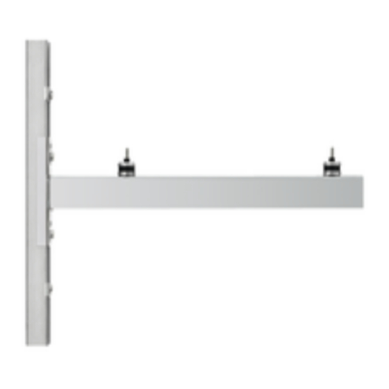
Anziehen der Schrauben aus. f Ziehen Sie alle Schrauben mit einem Schraubenschlüssel fest an. f Führen Sie die Schrauben mit den Unterlegscheiben von innen durch den Konsolenwinkel. f Schieben Sie die Schiebemuttern wie abgebildet in die Fixierhilfen hinein. WK 2... -
Seite 4: Technische Daten
Hinweis 5. Technische Daten Tragegurte zum Transportieren des Gerätes können Sie an den grau markierten Bereichen unten am Ge- Datentabelle stellrahmen einhaken. WK 2 f Schrauben Sie die Gerätefüße vom Außengerät ab. Entsor- 234722 gen Sie die Gerätefüße. Schenkellänge Gewichtsbelastung f Schrauben Sie die Gummipuffer in die dargestellten Posi- Geeignet für... -
Seite 5: General Information
- Slide nut M10 (2x) - Washer 12.5 x 36 x 2 mm (14x) - Washer 8.5 x 20.5 x 2 mm (4x) - System rail 800 mm (2x) - System rail 880 mm (2x) - Slide nut with fixing aid M12 (8x) - Rubber buffer (4x) - End cap (6x) WK 2... - Seite 6 If required, align the system rails by undoing and tighten- ing the bolts. f Tighten all the bolts securely with a spanner. f Insert the bolts with washers through the angular bracket from the inside. f Slide the slide nuts, as illustrated, into the fixing aids. WK 2...
-
Seite 7: Specification
Data table f Undo the appliance feet from the external unit. Dispose of WK 2 the appliance feet. 234722 Support length f Screw the rubber buffers into the illustrated positions on Weight the external unit. -
Seite 8: Remarques Générales
- Plaquette taraudée M10 (x2) - Rondelle 12,5 x 36 x 2 mm (x14) - Rondelle 8,5 x 20,5 x 2 mm (x4) - Profilé mural 800 mm (2x) - Profilé mural 880 mm (2x) - Plaquette taraudée avec agrafe à visser (x8) - Tampon caoutchouc (x4) - Embout de profilé (x6) WK 2... -
Seite 9: Travaux Préparatoires
Serrez fermement toutes les vis à l’aide d’une clé. f Introduisez les vis munies de leur rondelle par l’intérieur au travers de l’équerre. f Insérez les plaquettes taraudées dans les agrafes à visser comme illustré. WK 2... -
Seite 10: Données Techniques
Vous pouvez accrocher les sangles de transport dans les zones grisées en bas du châssis. Tableau de données f Dévissez les pieds de l’appareil extérieur. Mettez-les au WK 2 rebut. 234722 Longueur du bras f Vissez les tampons caoutchouc sous l’appareil extérieur Poids admissible comme indiqué... -
Seite 11: Algemene Aanwijzingen
- Klembeugel M12 (10x) - Schuifmoer M10 (2x) - Onderlegschijf 12,5 x 36 x 2 mm (14x) - Onderlegschijf 8,5 x 20,5 x 2 mm (4x) - Systeemrail 800 mm (2x) - Systeemrail 880 mm (2x) - Schuifmoer met fixeerhulpmiddel M12 (8x) - Rubberbuffer (4x) - Afsluitdop (6x) WK 2 | 11... - Seite 12 Pas de uitlijning van de montagerails, indien nodig, aan door de schroeven losser of vaster te draaien. f Draai alle schroeven met een schroefsleutel stevig vast. f Steek de schroeven met de onderlegschijven van binnen af door de consolehoek. 12 | WK 2...
-
Seite 13: Technische Gegevens
5. Technische gegevens u op de grijs gemarkeerde plaatsen onderaan op het frame inhaken. Gegevenstabel f Schroef de voeten van het buitentoestel af. Verwijder de WK 2 voeten. 234722 Beenhoogte f Schroef de rubberbuffers in de weergegeven posities in Belastbaarheid het buitentoestel. -
Seite 14: Avvertenze Generali
- Rondella 12,5 x 36 x 2 mm (14x) - Rondella 8,5 x 20,5 x 2 mm (4x) - Guida del sistema 800 mm (2x) - Guida del sistema 880 mm (2x) - Dado scorrevole con ausilio per fissaggio M12 (8x) - Tampone di gomma (4x) - Tappo di chiusura (6x) 14 | WK 2... -
Seite 15: Operazioni Preliminari
Se necessario, regolare le guide del sistema svitando e riavvitando le viti. f Serrare tutte le viti con una chiave apposita. f Infilare le viti con le rispettive rondelle nell'angolare di fis- saggio dall'interno. WK 2 | 15... -
Seite 16: Dati Tecnici
5. Dati tecnici f Svitare i piedini dall'unità esterna. Smaltire i piedini Tabella dei dati dell'unità. WK 2 f Avvitare i tamponi di gomma nelle posizioni indicate 234722 sull'unità esterna. Lunghezza del fianco Carico... -
Seite 17: Obecné Pokyny
- Posuvná matice M10 (2x) - Podložka 12,5 x 36 x 2 mm (14x) - Podložka 8,5 x 20,5 x 2 mm (4x) - Systémová lišta 800 mm (2x) - Systémová lišta 880 mm (2x) - Posuvná matice s fixační pomůckou M12 (8x) - Tlumič vibrací (4x) - Krytka (6x) WK 2 | 17... - Seite 18 Systémové lišty podle potřeby vyrovnejte uvolněním a utažením šroubů. f Všechny šrouby dotáhněte klíčem. f Šrouby s podložkami veďte zevnitř úhelníkem konzoly. f Posuvné matice zasuňte do fixačních pomůcek podle vyobrazení. f Šrouby utáhněte pomocí posuvných matic. 18 | WK 2...
-
Seite 19: Technické Údaje
Upozornění 5. Technické údaje Nosné popruhy k přenášení a přepravě přístroje mů- žete instalovat v šedě označené části pod rámem pří- Tabulka údajů stroje. WK 2 f Odšroubujte patky z venkovního přístroje. Zlikvidujte 234722 patky přístroje. Délka ramena Hmotnostní zatížení f Tlumiče vibrací našroubujte do zobrazených poloh na Vhodné... -
Seite 20: Yleisiä Ohjeita
- Kiinnikkeet M12 (10x) - Liukumutterit M10 (2x) - Aluslevyt 12,5 x 36 x 2 mm (14x) - Aluslevyt 8,5 x 20,5 x 2 mm (4x) - Järjestelmäkiskot 800 mm (2x) - Järjestelmäkiskot 880 mm (2x) - Liukumutterit ja kiinnitysapulaatat M12 (8x) - Kumipuskurit (4x) - Päätylevyt (6x) 20 | WK 2... - Seite 21 Kiristä kaikki ruuvit kiintoavaimella. f Työnnä ruuvit aluslevyineen sisäpuolelta kannatinkulman läpi. f Työnnä liukumutterit kuvan mukaisesti kiinnitysapulaattoihin. f Kiristä ruuvit liukumuttereilla. f Kierrä ruuvit löyhästi kiinni. Varmista, että liukumutterit ovat kohdistettuina poikittain kannatinkulmiin. WK 2 | 21...
-
Seite 22: Tekniset Tiedot
Ohje 5. Tekniset tiedot Nostohihnat voidaan kiinnittää laitteen rungon alle harmaalla merkitylle alueelle. Taulukko f Ruuvaa jalat irti ulkoyksiköstä. Hävitä jalat. WK 2 234722 f Ruuvaa kumipuskurit kiinni ulkoyksikköön kuvan osoitta- Sivupituus miin kohtiin. Painokuormitus Soveltuu 15/20/25 AC(S) - Seite 23 MUISTIINPANOT WK 2 | 23...
- Seite 24 STIEBEL ELTRON GmbH & Co. KG tecalor GmbH Dr.-Stiebel-Str. 33 | 37603 Holzminden Lüchtringer Weg 3 | 37603 Holzminden Tel. 05531 702-0 | Fax 05531 702-480 Tel. 05531 99068-700 | Fax 05531 99068-712 info@stiebel-eltron.de info@tecalor.de www.stiebel-eltron.de www.tecalor.de 4 < A M H C M O = c a a c e g >...