Werbung
Verfügbare Sprachen
Verfügbare Sprachen
Quicklinks
Kurzanleitung
deutsch
Condensed guide
english
Notice résumée
français
Istruzioni brevi
italiano
Instrucciones breves
español
简明指南
中文
Balluff GmbH
Schurwaldstrasse 9
73765 Neuhausen a.d.F.
Germany
Phone +49 7158 173-0
Fax +49 7158 5010
Service-Center +49 7158 173-370
service@balluff.de
www.balluff.com
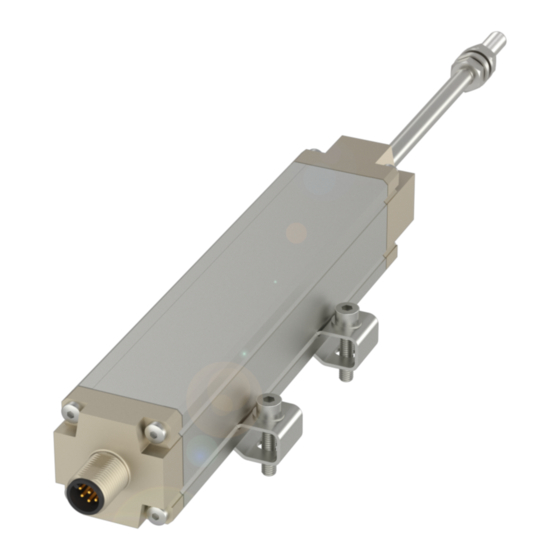
BIW1-A/C/E/G310-M_ _ _ _-P1-S115
Werbung

Verwandte Anleitungen für Balluff BIW1-A310-Mxxxx-P1-S115 series


Inhaltszusammenfassung für Balluff BIW1-A310-Mxxxx-P1-S115 series
- Seite 1 BIW1-A/C/E/G310-M_ _ _ _-P1-S115 Kurzanleitung deutsch Condensed guide english Notice résumée français Istruzioni brevi italiano Instrucciones breves español 简明指南 中文 Balluff GmbH Schurwaldstrasse 9 73765 Neuhausen a.d.F. Germany Phone +49 7158 173-0 Fax +49 7158 5010 Service-Center +49 7158 173-370 service@balluff.de www.balluff.com...
-
Seite 2: Bestimmungsgemäße Verwendung
Lage der Befestigungsklammern Betriebsanleitung sind die empfohlenen Abstände zu Eine ausführliche Betriebsanleitung beachten. erhalten Sie im Internet unter 1. Wegaufnehmer zur Schubstange www.balluff.com\downloads-biw ausrichten. oder per E-Mail anfordern bei 2. Befestigungsschrauben mit service@balluff.de max. 2 Nm anziehen. Befestigungsklammern und Zylinderkopfschrauben DIN 912 M4 ×... -
Seite 3: Anschlüsse
BIW1-A/C/E/G310-M_ _ _ _-P1-S115 Micropulse Wegaufnehmer im Profilgehäuse Anschlüsse BIW1-A310... BIW1-C310... BIW1-E310... BIW1-G310... Kabel BKS Ausgangssignal: GY grau 0...10 V 0...20 mA 4...20 mA -10...+10 V GN grün Versorgungsspannung: BU blau +24 V DC BN braun Steigungsauswahl: Steigungsauswahl - YE gelb Steigungsauswahl + RD rot Reservierte Adern müssen frei bleiben. - Seite 4 A detailed user's manual can be 1. Align transducer with sliding obtained on the Internet at rod. www.balluff.com\downloads-biw 2. Tighten mounting screws to a or E-mail requests can be made to maximum of 2 Nm. service@balluff.de Mounting brackets and M4 × 20 cylinder head screws, DIN 912, max.
- Seite 5 BIW1-A/C/E/G310-M_ _ _ _-P1-S115 Micropulse Transducer in Profile Housing Wiring BIW1-A310... BIW1-C310... BIW1-E310... BIW1-G310... Cable BKS Output signal: GY gray 0...10 V 0...20 mA 4...20 mA -10...+10 V GN green Supply voltage: BU blue +24 V DC BN brown Output slope: Output slope - YE yellow Output slope +...
-
Seite 6: Utilisation Prescrite
Vous trouverez une notice d'utilisation distances recommandées. détaillée sur le site Internet 1. Orientez le capteur de déplace- www.balluff.com\downloads-biw ment vers la barre coulissante. peut être demandée par e-mail à 2. Serrez les vis de fixation avec service@balluff.de un couple d’au plus 2 Nm. - Seite 7 BIW1-A/C/E/G310-M_ _ _ _-P1-S115 Capteur de déplacement Micropulse en boîtier profilé Branchements BIW1-A310... BIW1-C310... BIW1-E310... BIW1-G310... Câble BKS Signal de sortie : GY gris 0...10 V 0...20 mA 4...20 mA -10...+10 V GN vert Tension d'alimentation : BU bleu +24 V DC BN marron Coix de la pente : choix de la pente -...
- Seite 8 Internet all'indirizzo fissaggio, rispettare le distanze www.balluff.com\downloads-biw raccomandate. oppure può essere richiesto invian- 1. Allineare il trasduttore di do un’e-mail a service@balluff.de posizione con la biella. 2. Serrare le viti di fissaggio con max. 2 Nm. Lungh. nom.
- Seite 9 BIW1-A/C/E/G310-M_ _ _ _-P1-S115 Trasduttori di posizione Micropulse nel contenitore a profilo Connessioni BIW1-A310... BIW1-C310... BIW1-E310... BIW1-G310... Cavo BKS Segnale di uscita: GY grigio 0...10 V 0...20 mA 4...20 mA -10...+10 V GN verde Tensione di alimentazione: BU blu +24 V DC BN marrone Selezione del gradiente: Selezione del gradiente -...
- Seite 10 2. Apretar los tornillos de fijación a service@balluff.de a un máx. de 2 Nm. Longitud nominal Pinzas de fijación y tornillos de cabeza cilíndrica DIN 912 M4 × 20, máx. par de giro 2 Nm BIW1-...-M0100-P1-S115...
- Seite 11 BIW1-A/C/E/G310-M_ _ _ _-P1-S115 Transductor de desplazamiento Micropulse en carcasa perfilada Conexiones BIW1-A310... BIW1-C310... BIW1-E310... BIW1-G310... Kabel BKS Señal de salida: GY gris 0...10 V 0...20 mA 4...20 mA -10...+10 V GN verde Tensión de alimentación: BU azul +24 V DC BN marrón Selección de ascenso: selección de ascenso -...
- Seite 12 使用 BIW 位移传感器前须将其安装 在位移传感器附近不允许出 在机器或设备内部。传感器与控制系 现强电磁场。 统(PLC)组成一套行程测量系统, 并只能应用于此项用途。 可选定任意位置安装。通过附带的固 定夹将位移传感器安装于设备的平整 表面上。固定夹的位置确定应按照所 使用说明书 推荐的间距要求。 请登录我们公司网站 www.balluff. 1. 将位移传感器装在推杆部位。 com/downloads-biw 获取详细的操作 2. 将固定螺丝旋紧,最大扭力不超 说明书,或通过电子邮件向我们索 过 2Nm。 取。邮箱地址为 service@balluff.de。 固定夹和柱头螺丝 DIN 912 M4 × 20, 最大拧紧扭矩 2 Nm BIW1-...-M0100-P1-S115 额定长度 100 A = 200 外壳长度...
- Seite 13 BIW1-A/C/E/G310-M_ _ _ _-P1-S115 外置式微脉冲位移传感器 接口 针脚 BIW1-A310... BIW1-C310... BIW1-E310... BIW1-G310... BKS 电缆 输出信号: GY 灰色 0...10 V 0...20 mA 4...20 mA -10...+10 V GN 绿色 供电电压: BU 蓝色 +24 V DC BN 棕色 曲线斜率选择: 曲线斜率选择 - YE 黄色 曲线螺距选择 + RD 红色...