Kemper KTS Einbau- Und Bedienungsanleitung
Comlog-modul
Inhaltsverzeichnis
Verfügbare Sprachen
Verfügbare Sprachen
Einbau- und Bedienungsanleitung
KEMPER KTS ComLog-Modul
Inhalt
1 Allgemeine Hinweise .........................................................................................................................2
2 Sicherheitshinweise ...........................................................................................................................2
3 Technische Informationen .................................................................................................................3
3.1 Maße und Aufbau ......................................................................................................................3
3.2 Lieferumfang ..............................................................................................................................3
3.3 Technische Daten .......................................................................................................................3
4 Montage und Installation .................................................................................................................4
4.1 Allgemeines ................................................................................................................................4
4.2 Vorbereitung ..............................................................................................................................4
4.3 Montage......................................................................................................................................4
4.4 Anschlussprinzip Busleitung an ThermoBoxen und ComLog-Modul.....................................5
4.5 Netzanschluss .............................................................................................................................5
4.6 Funktion / LED überprüfen ........................................................................................................6
4.7 Bedienung ...................................................................................................................................6
4.7.1
Datenspeicherung gemessener Werte ....................................................................... 6
4.7.2
DAT-Datei aufspielen und SD-Karte kontrollieren .................................................... 7
4.7.3
Log Datei konfigurieren............................................................................................... 8
5 Wartung und Instandhaltung ...........................................................................................................9
Figur 955 02
Kapitel
Inhaltsverzeichnis

Verwandte Anleitungen für Kemper KTS

Inhaltszusammenfassung für Kemper KTS
-
Seite 1: Inhaltsverzeichnis
Einbau- und Bedienungsanleitung KEMPER KTS ComLog-Modul Figur 955 02 Inhalt 1 Allgemeine Hinweise .........................2 2 Sicherheitshinweise ...........................2 3 Technische Informationen .........................3 3.1 Maße und Aufbau ........................3 3.2 Lieferumfang ..........................3 3.3 Technische Daten ........................3 4 Montage und Installation .........................4 4.1 Allgemeines ..........................4 4.2 Vorbereitung ..........................4... -
Seite 2: Allgemeine Hinweise
Allgemeine Hinweise Die Montage- und Inbetriebnahme des KEMPER KTS ComLog-Moduls sollte erst nach dem Lesen dieser Symbolindex Einbau- Bedienungsanleitung vorgenommen Hinweis: werden. Sie informiert ausführlich über die Montage, nützliche Information die Inbetriebnahme, die Funktionsweise und die Be- dienung des ComLog-Moduls. Die Einbau- und Bedie- nungsanleitung sollte beim Gerät verbleiben oder mit... -
Seite 3: Technische Informationen
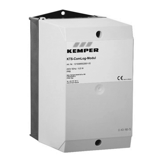
Technische Informationen 3.1 Maße und Aufbau Das ComLog-Modul ist wie folgt aufgebaut: Abbildung 1 – Aufbau ComLog-Modul Gehäusedeckel Gehäuseunterteil Netzteil 230V AC/ 24V DC ComLog mit SD-Karten-Slot mit SD Speicherkarte (1 GB) Modbus-Schnittstelle 3.2 Lieferumfang Im Lieferumfang enthalten: Gehäuse (IP65) ComLog-Modul SD-Karte (1 GB) Netzteil (230V AV / 24V DC) -
Seite 4: Montage Und Installation
Suchen Sie eine geeignete Montageposition und befestigen Sie das Gehäuse an dem dafür vorge- sehenen Einbauort. Anschließend werden die Regler der KTS-Thermo- Box(en) per Busleitung miteinander und mit dem ComLog-Modul verbunden, wie in der nachfol- genden Darstellung abgebildet ist. Dazu muss das Gehäuseoberteil entfernt werden. -
Seite 5: Anschlussprinzip Busleitung An Thermoboxen Und Comlog-Modul
4.4 Anschlussprinzip Busleitung an ThermoBoxen und ComLog-Modul 2-adrig 2-adrig 2-adrig Abbildung 2 - Anschlussprinzip Busleitung an ThermoBoxen und ComLog-Modul 4.5 Netzanschluss Warnhinweis: Anschluss Spannungsnetz Der Anschluss an das Spannungsnetz (~230 V / 50 Hz) Der Anschluss des ComLog-Moduls (~230 V / 50 Hz) nach einschlägigen ist nach den einschlägigen örtlichen EVU- und den... -
Seite 6: Funktion / Led Überprüfen
Log-Datei im DAT-Format SD-Karte abgelegt werden. Die Log-Datei wird durch den Kemper Service- techniker bei der Inbetriebnahme parametriert und auf die SD-Karte übertragen. Das ComLog- Modul legt durch die entsprechend konfi- gurierte Datei für jeden Tag eine CSV-Datei... -
Seite 7: Dat-Datei Aufspielen Und Sd-Karte Kontrollieren
DAT-Datei aufspielen und SD-Karte kontrollieren SD-Karte aus ComLog Modul entnehmen DAT-Datei von Rechner auf SD-Karte kopieren Zeitintervall-Aufzeichnung überprüfen (Empfehlung KEMPER 10 sec) SD-Karte in ComLog Modul einstecken Prüfen ob SD-Karte aufzeichnet SD-Karte aus ComLog Modul entnehmen (nach ca. 10 Minuten) SD-Karte mit Rechner auslesen Temperaturfühlerwerte überprüfen... -
Seite 8: Log Datei Konfigurieren
4.7.3 Log Datei konfigurieren An dem Beispiel einer KTS-ThermoBox als 2er Kaskade wird nachfolgend die Konfiguration der Log-Datei erläutert: Log-Datei mit dem Namen DAT.CSV in MS-EXCEL öffnen. In Zelle A1 wird angegeben, in welchen Abständen die Werte gespeichert werden. In diesem Beispiel wurde eine sekündliche Ablagerate festgelegt. -
Seite 9: Wartung Und Instandhaltung
Das Auslesen der Messwerte von der SD-Karte sollte in regelmäßigen Abständen aber mindestens im Abstand von 3 Monaten erfolgen. Abbildung 5 - Beispiel einer ComLog-Modul Auswertung Gebr. Kemper GmbH + Co. KG Harkortstr. 5, D-57462 Olpe Tel. +49 2761 891-0 Fax +49 2761 891-175 info@kemper-olpe.de...