Werbung
Quicklinks
Elektrischer Anschluss
Option:
/47
1
+UB
2
Q
3
0 V
4
Q
= Hellschaltung
= Dunkelschaltung
Technische Daten
Allgemeine Daten
Tastbereich
20 ... 700 mm
Tastbereich min.
20 ... 200 mm
Tastbereich max.
20 ... 700 mm
Hintergrundausblendung
max. + 10 % der oberen Tastbereichsgrenze
Lichtsender
IRED
Lichtart
infrarot, Wechsellicht , 880 nm
Schwarz-/Weiß-Differenz (6%/90%)
< 8 %
Lichtfleckdurchmesser
ca. 24 mm im Abstand von 700 mm
Öffnungswinkel
Sender 2°,
Empfänger 2°
Fremdlichtgrenze
50000 Lux
Kenndaten funktionale Sicherheit
MTTF
720 a
d
Gebrauchsdauer (T
)
20 a
M
Diagnosedeckungsgrad (DC)
0 %
Anzeigen/Bedienelemente
Betriebsanzeige
LED grün
Funktionsanzeige
2 LEDs gelb
ein: Objekt innerhalb des Tastbereiches\aus: Objekt außerhalb des Tastbereiches
Bedienelemente
Tastweiteneinsteller , Hell-/Dunkel-Umschalter
Elektrische Daten
Betriebsspannung
U
10 ... 30 V DC
B
Welligkeit
10 %
≤ 40 mA
Leerlaufstrom
I
0
Ausgang
Schaltungsart
hell-/dunkelschaltend umschaltbar
Signalausgang
2 PNP, antivalent, kurzschlussfest, verpolgeschützt , offene Kollektoren
Schaltspannung
max. 30 V DC
Schaltstrom
max. 200 mA
Schaltfrequenz
f
250 Hz
Ansprechzeit
2 ms
Umgebungsbedingungen
Umgebungstemperatur
-40 ... 60 °C (-40 ... 140 °F)
Lagertemperatur
-40 ... 75 °C (-40 ... 167 °F)
Mechanische Daten
Schutzart
IP67
Anschluss
Gerätestecker M18, 4-polig
Material
Gehäuse
Kunststoff ABS
Lichtaustritt
Kunststoff
Stecker
Kunststoff
Masse
70 g
Normen- und Richtlinienkonformität
Richtlinienkonformität
EMV-Richtlinie 2004/108/EG
EN 60947-5-2:2007 + A1:2012
Normenkonformität
Produktnorm
EN 60947-5-2:2007 + A1:2012
IEC 60947-5-2:2007 + A1:2012
Normen
UL 60947-5-2: 2014
EN 62471:2008
Zulassungen und Zertifikate
II, Bemessungsspannung ≤ 250 V AC bei Verschmutzungsgrad 1-2 nach IEC 60664-1
Schutzklasse
UL-Zulassung
E87056 , cULus Listed , "Class 2"-Netzteil , Type Rating 1
Sicherheitshinweise:
•
Vor der Inbetriebnahme Betriebsanleitung lesen
•
Anschluss, Montage und Einstellung nur durch Fachpersonal
•
Kein Sicherheitsbauteil gemäß EU-Maschinenrichtlinie
Abmessungen
Bedruckung
Typenbezeichnung
Anschlussbild
LED-Anzeige Schaltzustand
LED-Anzeige Betrieb
Tastweiteneinsteller
Electrical connection
Option:
/47
1
+UB
2
Q
3
0 V
4
Q
1
4
2
3
54.3
14.8
8
25.8
ø5
Sender
Empfänger
Schwalbenschwanz-
aufnahme
9.8
5
10
ø24.5
23.5
8
51.8
Ansicht X ohne Winkeldose
X
Hell-/Dunkel-Schalter
LED-Anzeige
Schaltzustand
Adressen/Addresses
Pepperl+Fuchs GmbH
68301 Mannheim · Germany
Tel. +49 621 776-4411
Fax +49 621 776-27-4411
E-mail: fa-info@de.pepperl-fuchs.com
Worldwide Headquarters
Pepperl+Fuchs GmbH · Mannheim · Germany
E-mail: fa-info@de.pepperl-fuchs.com
USA Headquarters
Pepperl+Fuchs Inc. · Twinsburg · USA
E-mail: fa-info@us.pepperl-fuchs.com
= Light on
= Dark on
Asia Pacific Headquarters
Pepperl+Fuchs Pte Ltd · Singapore
E-mail: fa-info@sg.pepperl-fuchs.com
Company Registration No. 199003130E
www.pepperl-fuchs.com
Technical data
General specifications
Detection range
Detection range min.
Detection range max.
Background suppression
Light source
Light type
Black/White difference (6 %/90 %)
Diameter of the light spot
Angle of divergence
Ambient light limit
Functional safety related parameters
MTTF
d
Mission Time (T
)
M
Diagnostic Coverage (DC)
Indicators/operating means
Operation indicator
Function indicator
Control elements
Electrical specifications
Operating voltage
U
B
Ripple
No-load supply current
I
0
Output
Switching type
Signal output
Switching voltage
Switching current
Switching frequency
f
Response time
Ambient conditions
Ambient temperature
Storage temperature
Mechanical specifications
Degree of protection
Connection
Material
Housing
Optical face
Connector
Mass
Compliance with standards and directives
Directive conformity
EMC Directive 2004/108/EC
Standard conformity
Product standard
Standards
Approvals and certificates
Protection class
UL approval
Security Instructions:
•
Read the operating instructions before attempting commissioning
•
Installation, connection and adjustments should only be undertaken by specialist personnel
•
Not a safety component in accordance with the EU Machinery Directive
Dimensions
Print
Type code
Connection diagram
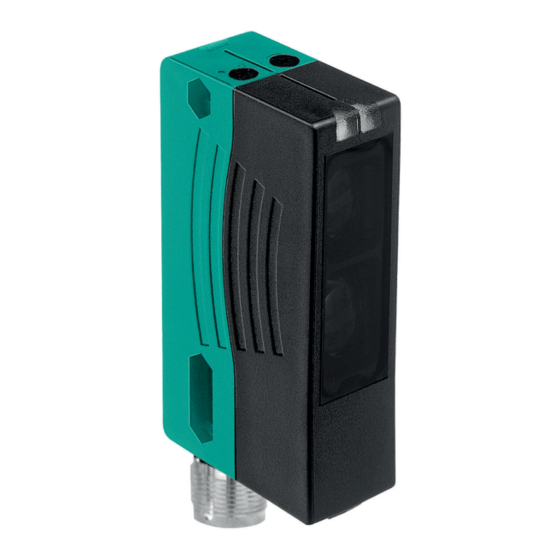
Reflexions-Lichttaster HGA
mit Kunststoffstecker M18 x 1, 4-polig
Background suppression sensor
with 4-pin, M18 x 1 plastic connector
RL28-8-H-700-IR/47/74
20 ... 700 mm
20 ... 200 mm
20 ... 700 mm
max. + 10 % of the upper limit of the detection range
IRED
modulated infrared light , 880 nm
< 8 %
approx. 24 mm at a distance of 700 mm
transmitter 2°
receiver 2°
50000 Lux
720 a
20 a
0 %
LED green
2 LEDs yellow
ON: object inside the scanning range
OFF: object outside the scanning range
Detection range adjuster , Light/Dark switch
10 ... 30 V DC
10 %
≤ 40 mA
light/dark on switchable
2 PNP, complementary, short-circuit protected, reverse polarity protected , open collectors
max. 30 V DC
max. 200 mA
250 Hz
2 ms
-40 ... 60 °C (-40 ... 140 °F)
-40 ... 75 °C (-40 ... 167 °F)
IP67
connector M18, 4-pin
Plastic ABS
plastic
plastic
70 g
EN 60947-5-2:2007 + A1:2012
EN 60947-5-2:2007 + A1:2012
IEC 60947-5-2:2007 + A1:2012
UL 60947-5-2: 2014
EN 62471:2008
II, rated voltage ≤ 250 V AC with pollution degree 1-2 according to IEC 60664-1
E87056 , cULus Listed , class 2 power supply , type rating 1
54.3
14.8
8
25.8
ø5
Emitter
Receiver
9.8
5
10
ø24.5
23.5
8
51.8
LED indicator:
X
switching state
Light/dark switch
LED indicator:
operation
LED indicator:
switching state
sensing range
adjuster
Dovetail mount
View X without angle junction box
Werbung

Inhaltszusammenfassung für Pepperl+Fuchs RL28-8-H-700-IR/47/74
- Seite 1 Pepperl+Fuchs GmbH 68301 Mannheim · Germany Tel. +49 621 776-4411 Fax +49 621 776-27-4411 E-mail: fa-info@de.pepperl-fuchs.com Worldwide Headquarters Pepperl+Fuchs GmbH · Mannheim · Germany E-mail: fa-info@de.pepperl-fuchs.com USA Headquarters Pepperl+Fuchs Inc. · Twinsburg · USA E-mail: fa-info@us.pepperl-fuchs.com = Hellschaltung = Light on...
- Seite 2 Intended use: The transmitter and receiver are located in the same housing for direct detection Charakteristische Ansprechkurve Characteristic response curve sensors with background masking. Marking of objects outside the detection range Courbe de response caractéristique Curva de respuesta característica is achieved by arranging the angle between the transmitter and receiver (2 recei- Curve di risposta caratteristica ver elements).


