Werbung
Quicklinks
DELTA
Taste sys Jalousie
Pushbutton sys shutter
Bedien- und Montageanleitung
Operating and mounting instructions
Stand:
Januar 2008
As at:
January 2008
A
B
B1
B2
B3
C
211
Produkt- und Funktionsbeschreibung
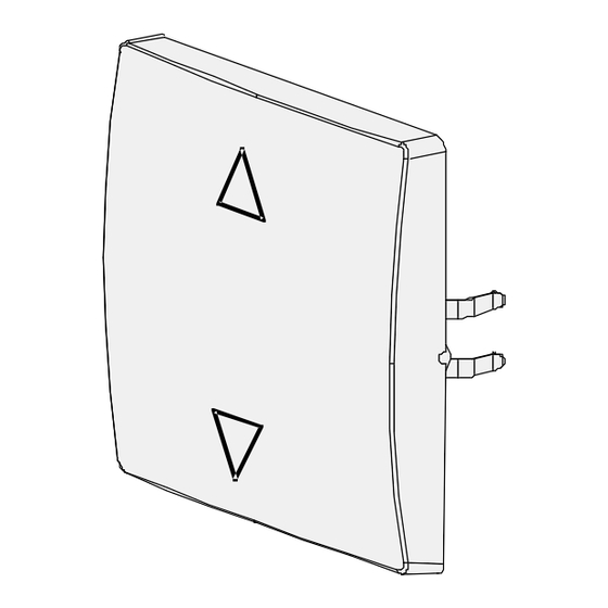
Die Taste sys Jalousie (Bild A) wird für die Bedienung des
Jalousiesteuerung Einsatzes sys verwendet. Zusammen mit
den
zugehörigen
Rahmen
Schalterprogramme wird die Taste auf den Einsatz aufgesteckt
5TC1 3..
und abhängig von der Betätigung der Taste (OBEN, UNTEN)
erfolgt die Informationsübertragung über die spezifische 230V-
Anwenderschnittstelle (230V-AST).
Bedienkonzept:
Die Bedienung der Taste sys Jalousie kann OBEN oder UNTEN
erfolgen. Es wird zwischen einem AUF/AB- und STEP-Befehl
(d.h. Stop bzw. Lamelle schrittweise AUF/ZU) unterschieden.
STEP-Befehl (Betätigung kürzer 0,4s):
Betätigung OBEN
Betätigung UNTEN
AUF/AB-Befehl (Betätigung länger 0,4s):
Betätigung OBEN
Betätigung UNTEN
Technische Daten
Spannungsversorgung
erfolgt über die 230V-Anwenderschnittstelle (230V-AST) des
Jalousiesteuerung Einsatzes sys
Anschlüsse
10 polige Stiftleiste (230V-AST) zum Anschluss an den
Jalousie-steuerung Einsatz sys
Mechanische Daten
• Gehäuse: Kunststoff
• Abmessungen (L x B x T):
DELTA i-system
DELTA profil
DELTA style
• Gewicht: ca. 30g
• Brandlast: ca. 950kJ
• Montage: wird auf den Jalousiesteuerung Einsatz sys
aufgesteckt
Elektrische Sicherheit
• Verschmutzungsgrad (nach IEC 60664-1): 2
• Schutzart (nach EN 60529): IP 20
• Überspannungskategorie(nach IEC 60664-1): III
• Gerät erfüllt EN 60669-2-1
EMV-Anforderungen
EN60669-2-1
Umweltbedingungen
• Klimabeständigkeit: EN 50090-2-2
• Umgebungstemperatur im Betrieb: - 5 ... + 45°C
• Lagertemperatur: - 25 ... + 70°C
• rel. Feuchte (nicht kondensierend): 5% bis 93%
CE-Kennzeichnung
gemäss EMV-Richtlinie (Wohnbau), Niederspannungsrichtlinie
Installationshinweise
ACHTUNG:
Das Gerät darf nur in Verbindung mit dem Jalousiesteuerung
Einsatz sys in Innenräumen und für trockene Räume verwendet
werden.
U
WARNUNG
• Das Gerät darf nur von einer zugelassenen Elektrofachkraft
montiert und in Betrieb genommen werden.
• Das Gerät darf nicht geöffnet werden.
• Die geltenden Sicherheits- und Unfallverhütungsvorschrif-ten
sind zu beachten.
Montage
Die Taste sys Jalousie wird zusammen mit dem zugehörigen
Rahmen auf den Jalousiesteuerung Einsatz sys aufgesteckt.
Dabei wird die elektrische Verbindung zwischen der Taste und
dem Einsatz über die 230V-AST hergestellt.
Montage: Bild B
B1 Jalousiesteuerung Einsatz sys
B2 Rahmen
B3 Taste sys Jalousie
1) Der Jalousiesteuerung Einsatz sys ist in der UP- Dose
angeschlossen und befestigt (siehe Montageanleitung
Jalousiesteuerungs Einsatz sys).
2) Stecken Sie die Taste sys Jalousie mit dem zugehörigen
Rahmen auf den Jalousiesteuerung Einsatz sys.
Demontage: Bild C
Abziehen der Taste sys Jalousie gemeinsam mit dem
zugehörigen Rahmen per Hand.
Achtung:
Für die Integration der Tasten sys Jalousie in das Programm
DELTA profil sind ausgeschnittene Rahmen zu verwenden!
Allgemeine Hinweise
• Ein defektes Gerät ist an die zuständige Geschäftsstelle der
Siemens AG zu senden.
• Bei zusätzlichen Fragen zum Produkt wenden Sie sich bitte
an unseren Technical Support:
℡
+49 (0) 180 50 50-222
+49 (0) 180 50 50-223
adsupport@siemens.com
D
(separat
zu
bestellen)
der
STOP/Lamelle AUF
STOP/Lamelle ZU
AUF-Fahrbefehl
AB-Fahrbefehl
55x55x24 mm (incl. Feder)
65x65x25 mm (incl. Feder)
68x68x27 mm (incl. Feder)
GB
Product and Applications Description
The pushbutton sys shutter (Diagram A) is used for the operation
of the shutter control insert sys. The pushbutton is clipped onto
the insert together with the relevant frame of the switch ranges
(to be ordered separately) and the transmission of information is
carried out via the specific 230V physical external interface
(230V-PEI), depending on the respective pushbutton action
(TOP, BOTTOM).
Operational concept:
The pushbutton actions of the pushbutton sys shutter can be
carried out at the TOP or BOTTOM. The commands UP, DOWN
and STEP (i.e. stop or stepwise movement of the louvres
OPEN/CLOSED) are available.
STEP command (Actions shorter than 0.4s):
TOP
STOP/louvres OPEN
BOTTOM
STOP/louvres CLOSED
UP/DOWN command (Actions longer than 0.4s):
TOP
UP movement command
BOTTOM
DOWN movement command
Technical Specifications
Power supply
via the 230V physical external interface (230V-PEI) of the shutter
control insert sys.
Connections
10 pin bar (230V-PEI) for connection to the shutter control insert
sys.
Mechanical specifications
• Housing: plastic
• Dimensions (L x W x D):
DELTA i-system
55x55x24mm (including spring)
DELTA profil
65x65x25mm (including spring)
DELTA style
68x68x27mm (including spring)
• Weight: approx. 30g
• Fire load: approx. 950kJ
• Mounting: placed on the shutter control insert sys
Electrical safety
• Pollution degree (according to IEC 60664-1): 2
• Protection (according to EN 60529): IP 20
• Overvoltage category (according to IEC 60664-1): III
• Device complies with EN 60669-2-1
Electromagnetic compatibility
EN60669-2-1
Environmental specifications
• Climatic conditions: EN 50090-2-2
• Ambient operating temperature: - 5 ... + 45°C
• Storage temperature: - 25 ... + 70°C
• Relative humidity (non-condensing): 5% to 93%
CE norm
complies with the EMC regulations (residential buildings),
low voltage regulations
Installation Instruction
CAUTION:
The device may be used for interior installations and in dry rooms
only in connection with the shutter control insert sys.
U
WARNING
• The device must be mounted and commissioned by an
authorised electrician.
• The device must not be opened.
• The prevailing safety and accident regulations must be
observed.
Mounting
The pushbutton sys shutter is clipped onto the shutter control
insert sys together with its frame. The electrical connection
between the pushbutton and the insert is thus established via the
230V-PEI.
Mounting: Diagram B
B1 Shutter control insert sys
B2 Frame
B3 Pushbutton sys shutter
1) The shutter insert sys is connected and mounted inside the
flush-type box (see mounting instructions for shutter control
insert sys).
2) Place the pushbutton sys shutter together with its frame onto
the shutter control insert sys.
Dismantling: Diagram C
Remove the pushbutton sys shutter manually together with its
frame.
Caution:
Cut-out frames have to be used to integrate the pushbutton sys
shutter into the DELTA profil range!
General Notes
• Any faulty devices should be returned to the local Siemens
office.
• If you have further questions concerning the product, please
contact our technical support:
℡
+49 (0) 180 50 50-222
+49 (0) 180 50 50-223
adsupport@siemens.com
251652.41.02 ,,DS07´´
Werbung

Verwandte Anleitungen für Siemens Delta 5TC1 3 Serie


Inhaltszusammenfassung für Siemens Delta 5TC1 3 Serie
- Seite 1 Allgemeine Hinweise General Notes • Ein defektes Gerät ist an die zuständige Geschäftsstelle der • Any faulty devices should be returned to the local Siemens Siemens AG zu senden. office. • Bei zusätzlichen Fragen zum Produkt wenden Sie sich bitte •...
- Seite 3 Περιγραφ προ ντος και λειτουργ ας Ürün ve fonksiyon açıklaması DELTA Το μπουτ ν για περσ δες sys (εικ να A) χρησιμοποιε ται για το sys jaluzi düğmesi (Şekil A) jaluzi kumanda yuvası sys’in χειρισμ του μηχανισμο ελ γχου περσ δων sys. Το μπουτ ν για kontrolü...
- Seite 4 • Bozuk bir aygıt, Siemens AG’nin ilgili birimine geri • Τυχ ν ελαττωματικ ς συσκευ ς θα πρ πει να αποστ λλονται στα αρμ δια τμ ματα της Siemens AG. gönderilmelidir. • Σε περ πτωση που χετε ερωτ σεις σχετικ με το προ ν, •...
- Seite 5 Descripción del producto y de su funcionamiento Описание изделия и его функций DELTA La Tecla sys Persiana (Figura A) se utiliza para manejar el Клавиша sys жалюзи (рисунок A) используется для mecanismo del mando de persiana sys. Combinada con los управления...
- Seite 6 Общие указания • Si el aparato está defectuoso deberá enviarse a la • Неисправный прибор высылается в соответствующий correspondiente filial de Siemens. филиал Siemens AG. • Para cualquier consulta adicional sobre el producto, diríjase • В случае дополнительных вопросов по изделию...