Herunterladen Inhalt Inhalt Diese Seite drucken

Werbung

Verfügbare Sprachen
  • DE

Verfügbare Sprachen

  • DEUTSCH, seite 22
AB - BS
MANUALE D'ISTRUZIONI
OPERATOR'S MANUAL
CARNET D'INSTRUCTIONS
GEBRAUCHSANWEISUNG
MANUAL DE INSTRUCCIONES

Werbung

Inhaltsverzeichnis
loading

Inhaltszusammenfassung für Bras AB series

  • Seite 1 AB - BS MANUALE D’ISTRUZIONI OPERATOR’S MANUAL CARNET D’INSTRUCTIONS GEBRAUCHSANWEISUNG MANUAL DE INSTRUCCIONES...
  • Seite 2: Dichiarazione Di Conformità Ce

    DICHIARAZIONE DI CONFORMITÀ CE Noi Bras Internazionale spa - Via dei Pioppi, 33 - 20090 Opera - Milano - ITALY dichiariamo, sotto la nostra responsabilità, che i prodotti AB 1-2-3- 4/10, BS 11-12-13-14, BS 21-22-23-24 230V 50Hz sono conformi alle seguenti Normative:...
  • Seite 3: Garanzia

    ITALIANO ENGLISH FRANCAIS DEUTSCH ESPAÑOL GARANZIA L’apparecchio è garantito per un periodo di dodici mesi dalla prescrizioni indicate nelle apposite “Istruzioni”, concernenti in parti- data di acquisto. Tale data viene certificata dalla ricevuta e/o fattura colare le avvertenze in tema di installazione, uso e manutenzione fiscale e/o da un documento di consegna rilasciato dal Rivenditore.
  • Seite 4: Caratteristiche Tecniche

    I T A L I A N O A B - B S 1 CARATTERISTICHE TECNICHE 3 INSTALLAZIONE AB 1/10 AB 2/10 AB 3/10 AB 4/10 BS 11 BS 12 BS 13 BS 14 Estrarre il distributore dall’imballo, che è consigliabile con- BS 21 BS 22 BS 23...
  • Seite 5: Per Un Funzionamento Sicuro

    cacciavite) di uno dei due attacchi di drenaggio e collegarlo ad trato, secondo le istruzioni del fabbricante. Volendo utilizzare un tubo di scarico (vedere figura 1). spremute naturali è consigliabile filtrarle onde evitare che le parti solide in esse contenute possano ostruire il passaggio dal rubinetto.
  • Seite 6 I T A L I A N O A B - B S grigliati. Assicurarsi inoltre che il flusso d’aria non venga osta- gruppo pompa, rimuovere l’apposita spina di fissaggio (vedere colato dalla vicinanza di pareti, scatole o altro. Lasciare almeno figura 3).
  • Seite 7 assieme al coprirubinetto, dal contenitore bevanda(vedere quella orizzontale (3) sul fondo del contenitore (vedere figura figura 5). figura 5 figura 8 5. 3. 2. 2 LINEE BS CON RUBINETTO A GRAVITÀ Smontare il contenitore dall’apparecchio e capovolgerlo. Sganciare (1) la leva smontaggio rubinetto e contemporanea- mente ruotare (2) verso sinistra (senso antiorario) tutto il corpo Sfilare (1) il pistone e quindi smontare (2-3) la leva comando rubinetto (vedere figura 6).
  • Seite 8 I T A L I A N O A B - B S 5. 3. 4 SANITIZZAZIONE DEL DISTRIBU- 5. 3. 6 RIMONTAGGIO RUBINETTO TORE SMONTATO 5. 3. 6. 1 LINEE BS CON RUBINETTO A La sanitizzazione deve essere eseguita immediatamente prima di mettere in funzione il distributore;...
  • Seite 9: Manutenzione

    Montare (1-2) la leva di comando rubinetto e quindi infilare Premere (1) la leva comando rubinetto e tirare verso il basso (2) l’estremità del gommino rubinetto fino ad assestarlo (3) il pistone dotato della propria guarnizione (vedere figura completamente (vedere figura 15). 12).
  • Seite 10: Technical Characteristics

    EN GLIS H A B - B S 1 TECHNICAL CHARACTERISTICS keep them for possible future use. AB 1/10 AB 1/10 AB 1/10 AB 1/10 BS 11 BS 12 BS 13 BS 14 IMPORTANT BS 21 BS 22 BS 23 BS 24 Transparent removable bowls When handling the machine never grasp it by the bowls...
  • Seite 11: Operating Procedures

    operated by a mixing device switch (pump switch for BS lines, (chapter 5.3 CLEANING AND SANITAZING PROCEDURES). mixer switch for AB - BS2M line). Their functions are as follows: Power switch IMPORTANT Install the dispenser so that the plug is easily accessi- 0 position : power is turned OFF to all ble.
  • Seite 12: Cleaning And Sanitizing Procedures

    EN GLIS H A B - B S 5. 3 CLEANING AND SANITIZING tube from its vertical seat in the bowl bottom (see figure 4). PROCEDURES Cleaning and sanitizing of the dispenser are recommended to guarantee the conservation of the best product taste and the highest unit efficiency.
  • Seite 13 down. Remove the faucet body from the bowl (see figure 7). not provide adequate cleaning. IMPORTANT In order to prevent any damages to the dispenser use only a detergent suitable with plastics parts. Using a brush, suitable for the purpose, thoroughly clean all disassembled parts in the cleaning solution.
  • Seite 14 EN GLIS H A B - B S outside the bowl (see figure 9). arranged. (see figure 11). figure 11 5. 3. 6. 4 BS LINES WITH GRAVITY FAUCET figure 9 Fit the faucet body by reversing disassembly operations (see figure 7). Place bowl on the unit, with gasket around the cooling Install the faucet handle (1-2) and the piston with its gasket dome, then push it down all the way.
  • Seite 15: In-Place Sanitization

    6. 1 MAINTENANCE (TO BE CARRIED (see figure 14). OUT BY QUALIFIED SERVICE PERSONNEL ONLY) Montly: clean all internal components, primarily the condenser, using compressed air. To clean these internal parts, unplug the unit or switch off the 2- pole wall breaker, then remove front panel (dispensing side). Condenser fins are very sharp.
  • Seite 16: Caracteristiques Techniques

    F R A N C A I S A B - B S 1 CARACTERISTIQUES TECHNIQUES 3 INSTALLATION AB 1/10 AB 1/10 AB 1/10 AB 1/10 Sortir le distributeur de son emballage et garder celui-ci BS 11 BS 12 BS 13 BS 14 BS 21 BS 22...
  • Seite 17: Pour Un Fonctionnement Sans Danger

    5. 1 DESCRIPTION DES COMMANDES Quand le distributeur sort de l'usine, il n'est ni prélavé, ni désinfecté. Avant de l'utiliser, il faut le démonter, le laver et le désinfecter en suivant les instructions fournies dans ce carnet au chapitre 5.3 NETTOYAGE. Le distributeur est équipé...
  • Seite 18 F R A N C A I S A B - B S Afin d’éviter que certains produits (café, thé, lait d’amande, Enlever le joint du réservoir. etc.) moussent si agités par la pompe, appliquer à la même le dispositif réducteur du flux et le tube à arc (voir figure 2). Voir chapitre 5.3.2.
  • Seite 19 5. 3. 2. 2 LIGNES BS AVEC ROBINET EN Enlever le rèservoir de l’appareil et le retourner. Tirer (1) le levier de décrochement du robinet et en même INOX À GRAVITÈ temps tourner (2) vers gauche le corps du robinet jusqu’à le décrocher du réservoir avec le couvercle du robinet même (voir figure 5).
  • Seite 20 F R A N C A I S A B - B S 5. 3. 5 REMONTAGE Tirer (3) doucement le tuyau vers le bas jusqu’à le bien placer (voir figure 11). Introduire le tiroir égouttoir à sa place. Voir chapitre 5.3.6. REMONTAGE DU ROBINET. Replacer le joint du réservoir en laissant la couronne plus épaisse au dehors du réservoir (voir figure 9).
  • Seite 21: Entretien

    6 ENTRETIEN Enfiler son extrémité antérieure dans le siège vertical du corps du robinet (voir figure 14). Quotidiennement: contrôler le distributeur et vérifier qu'il n'y a pas de fuites de produit au niveau des joints. En cas de fuites, contrôler avant tout que le distributeur est monté correctement, puis vérifier que les joints n'ont pas besoin d'être lubrifiés et enfin qu'ils ne sont pas défectueux ou usés.
  • Seite 22: Technische Daten

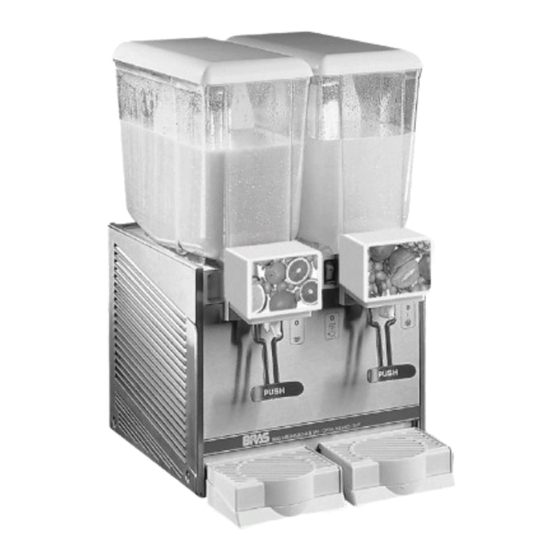
    D E U T S C H A B - B S 1 TECHNISCHE DATEN 3 INSTALLATION AB 1/10 AB 1/10 AB 1/10 AB 1/10 BS 11 BS 12 BS 13 BS 14 BS 21 BS 22 BS 23 BS 24 Den Dispenser aus seiner Verpackung nehmen.
  • Seite 23: Sicherheitsmaßnahmen

    Deckel Behälter setzen ordnungsgemäße Stellung der Behälter sicherstellen. Die Schalter betätigen (siehe Kapitel 5. 1 BESCHREIBUNG DER BETRIEBSSCHALTER). Der Dispenser muß immer mit montierten Deckeln betrieben werden, um der eventuellen Verschmutzung des Produkts vorzubeugen. Der Dispenser muß ununterbrochen funktionieren: Das Kühlaggregat schaltet automatisch ab, sobald das Produkt abgabefertig ist.
  • Seite 24: Zerlegen Des Zapfventils

    D E U T S C H A B - B S Diese Situation ist außer an der Blockierung der Schnecken lösen, den speziellen Haltestift entfernen (Bild 3). a u c h d ar an e r k en n ba r , da ß d a s G e r ä t e i n z ei t w ei l ig aussetzendes Geräusch abgibt.
  • Seite 25 5. 3. 2. 5 AB-LINIE Getränkebehälter schrauben (2) (Bild 5). 1 - Die Hahnabdeckung lösen und heben. Den Betätigungshebel des Hahns drücken (1) und den Gummischlauch des Hahns aus seinem vertikalen Sitz (2) im Hahnkörper und aus dem horizontalen Sitz (3) unten am Behälter entfernen (Bild 8).
  • Seite 26: Desinfektion Des Demontierten Dispensers

    D E U T S C H A B - B S BS-Linien: die Punpeneinheit wieder zusammenmontieren waschen. u n d i n d e n B e h ä l t e r e n t s p r e c h e n d e i n s e t z e n . I m entgegengesetzen ührzeigersinn drehen, bis Sie blockiertun richtig sitzt.
  • Seite 27 einfügen (Bild 12). Schlauch einwandfrei sitzt (Bild 15). Bild 15 Ventilkörper aufsetzen. 5. 4 DESINFEKTION DES MONTIERTEN Bild 12 DISPENSERS 5. 3. 6. 3 AB-LINIE Die Desinfektion des montierten Geräts vor seiner Inbetriebnahme kann, falls erforderlich, als zusätzliche Vorsichtsmaßnahme nach der oben beschriebenen Desinfektion des demontierten Geräts durchgeführt werden.
  • Seite 28: Caracteristicas Tecnicas

    ES PAÑ OL A B - B S 1 CARACTERISTICAS TECNICAS 3 INSTALACION AB 1/10 AB 1/10 AB 1/10 AB 1/10 Quitar el distribuidor del embalaje: guardar este último por BS 11 BS 12 BS 13 BS 14 BS 21 BS 22 BS 23 BS 24...
  • Seite 29: Para Un Funcionamiento Seguro

    5. 1 DESCRIPCION DE LOS MANDOS El distribuidor no sale de fábrica prelavado e higienizado. Antes de utilizarlo debe ser desarmado, lavado e higienizado siguiendo cuanto dicho en las presentes instrucciones del capítulo 5.3 LIMPIEZA. El distribuidor está provisto de un interruptor general y, para cada contenedor, de un interruptor para el mando del 4 PARA UN FUNCIONAMIENTO SEGURO dispositivo de agitación (bomba en la series BS y agitador en la...
  • Seite 30 ES PAÑ OL A B - B S puede aplicar al grupo un dispositivo reductor de flujo y el Quitar la junta del contenedor. propio tubo curvo (ver figura 2). Ver párrafo 5.3.2. SMONTAGGIO RUBINETTO. Sacar el cajón recoge-gotas y vaciarlo. 5.
  • Seite 31 5. 3. 2. 2 SERIES BS. GRIFO EN ACERO Desmontar contenedor ponerlo boca abajo. Desenganchar (1) la palanca de desmontaje del grifo y al INOX POR GRAVEDAD mismo tiempo girar (2) hacia la izquierda (sentido antihorario) todo el cuerpo del grifo hasta desengancharlo completamente junto al cubre-grifo (ver figura 5).
  • Seite 32 ES PAÑ OL A B - B S 5. 3. 5 REMONTAJE Tirar (3) ligeramente hacia abajo la extremidad del tubo goma hasta ajustarlo completamente (ver figura 11). Colocar el cajón recoge-gotas en su alojamiento. Ver párrafo 5.3.6. REMONTAJE GRIFO. Poner la junta al contenedor, de modo que el borde de mayor espesor se quede exteriormente al mismo contenedor (ver figura 9).
  • Seite 33 6 MANUTENCION Insertar la extremidad anterior en su sede vertical en el cuerpo del grifo (ver figura 14). Cada día: controlar el distribuidor y que no se verifiquen pérdidas de producto de las juntas. Si se notasen pérdidas, controlar , antes de todo, que el distribuidor esté montado correctamente, luego que las juntas no necesiten lubricación y, por último, que dichas juntas no sean defectuosas o estén gastadas, si es así...
  • Seite 34 2450_99 V 1.7 05G23 I T A L I A N O SCHEMA ELETTRICO: vedere AB ELENCO RICAMBI WIRING DIAGRAM: see AB EN GLIS H SPARE PARTS LIST SCHEMA ELECTRIQUE: voir AB SCHALTSCHEMA: siehe AB F R A N C A I S LISTE DES PIECES DE RECHANGE ESQUEMA ELECTRICO: ver AB D E U T S C H...
  • Seite 35 16 22800-02401 Corpo rubinetto Faucet body Corps du robinet Ventilkörper Cuerpo grifo 17 22800-02501 Forcella per rubinetto Faucet arm Bras du robinet Hebel Palanca en forma de horquilla 18 22800-02600 Molla rubinetto Faucet spring Ressort du robinet Ventilfeder Muelle grifo...
  • Seite 36 2450_99 V 1.5 04L21 I T A L I A N O ELENCO RICAMBI EN GLIS H SPARE PARTS LIST F R A N C A I S LISTE DES PIECES DE RECHANGE D E U T S C H ERSATZTEILLISTE ES PAÑ...
  • Seite 37 Panel lateral izquierdo 16 22800-02401 Corpo rubinetto Faucet body Corps du robinet Ventilkörper Cuerpo grifo 17 22800-02501 Forcella per rubinetto Faucet arm Bras du robinet Hebel Palanca en forma de hor- quilla 18 22800-02600 Molla rubinetto Faucet spring Ressort du robinet Feder...
  • Seite 38 I T A L I A N O SCHEMA ELETTRICO EN GLIS H WIRING DIAGRAM F R A N C A I S SCHEMA ELECTRIQUE D E U T S C H SCHALTSCHEMA ES PAÑ OL ESQUEMA ELECTRICO Interruttore Switch Interrupteur Schalter Interruptor...
  • Seite 39 NOTE - NOTES- NOTES - ANMERKUNGEN - NOTAS:...
  • Seite 40 Bras Internazionale spa Via dei Pioppi, 33 - 20090 Opera - Milano Tel. 02-57.68.071 - Fax 02-57.68.07.241 www.brasspa.com - E-mail: sales@brasspa.com 2450_99 V 2.0 06B13...

Inhaltsverzeichnis