Herunterladen Inhalt Inhalt Diese Seite drucken

Werbung

Verfügbare Sprachen
  • DE

Verfügbare Sprachen

  • DEUTSCH, seite 31
700 / 710
A
MTD Products Aktiengesellschaft • Saarbrücken • Germany
Part No: 769-01319
12/04

Werbung

Inhaltsverzeichnis
loading

Inhaltszusammenfassung für MTD 700

  • Seite 1 700 / 710 MTD Products Aktiengesellschaft • Saarbrücken • Germany Part No: 769-01319 12/04...
  • Seite 2 English Français Deutsch Italiano Português Español...
  • Seite 3 KNOW YOUR UNIT FAMILIARISEZ-VOUS AVEC L’APPAREIL LERNEN SIE IHR GERÄT KENNEN PANORAMICA SULL’UNITÀ FAMILIARIZE-SE COM A SUA MÁQUINA CONOZCA SU UNIDAD Description des pièces Description of Parts 1. Power Head 9. Interrupteur 9. Ignition Switch 1. Tête d'entraînement 2. Bouchon du carburant 10.
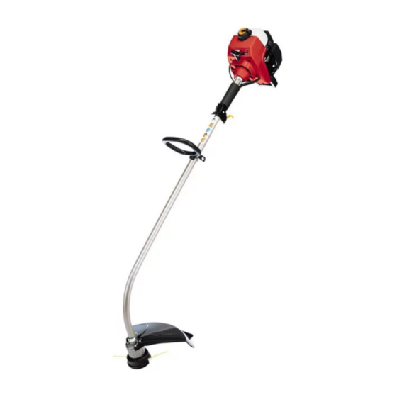
  • Seite 4 Descrição das peças Beschreibung der Teile 1. Motore 1. Motor 2. Tappo del serbatoio 2. Tankdeckel 3. Impugnatura del cavo per l'avvio 3. Griff des Anlassers 4. Candela 4. Zündkerze 5. Leva dello starter 5. Starterhebel 6. Cicchetto 6. Ansaugpumpe 7.
  • Seite 5 Description of Parts – Figs. 1–3 1. Shaft Tube Grip 6. Limiter Sleeve 2. Handle 7. Clamp Assembly 3. Wing Nut 8. Cutting Attachment Guard 4. Washer 9. Screws (4) 5. Bolt Description des pièces – Figs. 1–3 1. Poignée 6.
  • Seite 6 Description des pièces – Figs. 4-7 1. Manette des gaz 6. Position Marche (3) 2. Arrét (O) 7. Levier d'étrangleur 3. Marche (I) 8. Amorceur 4. Étranglement 9. Corde de démarrage maximum Position (1) 5. Position d'étranglement partielle (2) Fig. 4 Beschreibung der Teile –...
  • Seite 7 Fig. 11 Description of Parts – Figs. 10-11 1. Bolt 4. Spring Fig. 7 2. Bump Knob 5. Inner Reel 3. Outer Spool Description des pièces – Figs. 10-11 1. Bouton 3. Bobine extérieure 2. Bouton de butée 4. Ressort 5.
  • Seite 8 Fig. 16 Fig. 12 Fig. 17 Fig. 13 Fig. 18 Fig. 14 Description of Parts – Figs. 12-18 1. Indexing Teeth 3. Loop 2. Slotted Holes 4. Holding Slots Description des pièces – Figs. 12-18 1. Dents de 3. Boucle Fig.
  • Seite 9 Beschreibung der Teile – Abb. 12-18 1. Schaltzähne 3. Schlaufe 2. Schlitzförmige 4. Halteschlitze Löcher Descrizione dei componenti – figg. 12-18 1. Dente 3. Occhiello Fig. 21 Fig. 22 2. Asole 4. Fessure di bloccaggio Descrição das peças – Figuras 12-18 1.
  • Seite 10 Description of Parts – Figs. 24-25 1. Idle Speed Adjuster 2. Spark Plug Description des pièces – Figs. 24-25 1. Vis de réglage du 2. Bougie ralenti Beschreibung der Teile – Abb. 24-25 1. Lehrlaufdrehzahl- 2. Zündkerze regler Fig. 24 Descrizione dei componenti –...
  • Seite 11: Safe Operating Practices

    Enter all the information shown on the identification plate SAFE OPERATING PRACTICES of your lawn scarifier into the box below. USE THE UNIT CORRECTLY The identification plate is located on the engine. This unit is intended exclusively: This information is very important for identifying any –...
  • Seite 12 SAFETY WARNINGS WHILE OPERATING • If the unit should start to vibrate abnormally, stop the engine and check immediately for the cause. Vibration • Never start or run the unit inside a closed room or is generally a warning of trouble. building.
  • Seite 13 SAFETY AND INTERNATIONAL SYMBOLS This operator's manual describes safety and international symbols and pictographs that may appear on this product. Read the operator's manual for complete safety, assembly, operating and maintenance and repair information. SYMBOL MEANING SYMBOL MEANING • SAFETY ALERT SYMBOL •...
  • Seite 14 1. Mix petrol (gasoline) with oil. Fill fuel tank with fuel/oil control and hold. mixture. See Oil and Fuel Mixing Instructions. 700: Pull starter rope briskly 3 times (Fig. 6). 2. Put the ignition switch in the ON (I) position (Fig. 4).
  • Seite 15 OPERATING INSTRUCTIONS NOTE: The unit uses Advanced Starting Technology™, A blade in the cutting attachment guard will cut the line to the proper length if excess line is released. For best which significantly reduces the effort required to results, tap the Bump Head on bare ground or hard soil. If start the engine.
  • Seite 16: Air Filter Maintenance

    MAINTENANCE AND REPAIR INSTRUCTIONS Single Line Installation 7. Place the new inner reel inside the outer spool. Push the inner reel and outer spool together. While holding Go To Step 8 for Split-Line™ Installation the inner reel and outer spool, grasp the ends and pull 6.
  • Seite 17: Replacing The Spark Plug

    MAINTENANCE AND REPAIR INSTRUCTIONS Clean Air Filter 3. Replace cracked, fouled or dirty spark plug. Set the air gap at 0.5 mm (0.020 in.) using a feeler gauge The condition of the air filter is important to the operation (Fig. 24). of the unit.
  • Seite 18: Troubleshooting

    TROUBLESHOOTING ENGINE WILL NOT START C A U S E A C T I O N Empty fuel tank Fill fuel tank with properly mixed fuel Primer bulb wasn't pressed enough Press primer bulb fully and slowly 10 times Engine is flooded Squeeze the trigger and pull the starter rope (with choke in Position 3) Old or improperly mixed fuel...
  • Seite 19: Specifications

    SPECIFICATIONS ENGINE Engine Type............................Air-Cooled, 2-Cycle Ignition Type................................Electronic Displacement............................31 cm (1.9 cu. in.) Maximum Engine Performance in accordance with ISO 8893................75 kw (1 hp) Idle RPM..............................3200 min (rpm) Operating RPM............................7700 min (rpm) Fuel............................Fuel/Oil Mixture (40:1) 2,5 % Ignition Switch ...............................
  • Seite 21: Avertissements De Sécurité

    Reportez dans l'encadré ci-dessous toutes les POUR VOTRE SECURITE indications figurant sur la plaquette signalétique qui se trouve à proximité du moteur de l'appareil. UTILISATION CONFORME DE L’APPAREIL Les indications qu'elle contient sont d'une importance Cet appareil est exclusivement destiné à servir capitale car elles permettront plus tard de déterminer les –...
  • Seite 22: Pendant L'utilisation

    AVERTISSEMENTS DE SÉCURITÉ • Mélangez et ajoutez le carburant dans un lieu • En cas de contact avec un corps étranger, arrêtez le extérieur, aéré et propre, à l'abri d’étincelles ou de moteur immédiatement et vérifiez que l’appareil n’est flammes. Ne remplissez jamais le réservoir de pas endommagé.
  • Seite 23 AVERTISSEMENTS DE SÉCURITÉ SYMBOLES DE SECURITE ET SYMBOLES INTERNATIONAUX Le présent manuel d’utilisation décrit les symboles et pictogrammes de sécurité et internationaux susceptibles d’apparaître sur cet outil. Lisez le manuel d’utilisation pour obtenir des informations complètes sur la sécurité, le montage, le fonctionnement, l’entretien et la maintenance de votre matériel.
  • Seite 24 AVERTISSEMENTS DE SÉCURITÉ SYMBOLE SIGNIFICATION • INTERRUPTEUR MARCHE • INTERRUPTEUR ARRET • ATTENTION SURFACE CHAUDE Ne touchez pas un pot d’échappement ou un cylindre chaud. Vous risqueriez de vous brûler. Ces éléments chauffent énormément lorsque l’appareil est en fonctionnement. Une fois qu’il est arrêté, ils restent chauds pendant un court moment.
  • Seite 25: Instructions De Montage

    INSTRUCTIONS DE MONTAGE INSTALLATION DE LA POIGNEE EN D 3. Tout en maintenant l’appareil en position de fonctionnement (Fig. 13), placez la poignée en D à 1. Pour votre sécurité, la poignée en D doit être l’endroit qui vous assure la meilleure prise en main et assemblée à...
  • Seite 26 Le fil de coupe peut se rompre dans les cas suivants : 700: Tirez énergiquement le câble du lanceur (vous • Usure normale du fil devrez généralement répéter le lancement 3 fois) (Fig.
  • Seite 27: Entretien Et Réparations

    ENTRETIEN ET RÉPARATIONS INSTALLATION DU FIL DE COUPE 13. Insérez les extrémités du fil dans les œillets de la bobine extérieure et placez le moulinet et le ressort Cette section couvre l’installation de fil Split-Line dans la bobine (Fig. 18). Enfoncez le moulinet et la l’installation de fil simple standard.
  • Seite 28: Remplacement De La Bougie

    ENTRETIEN ET RÉPARATIONS 4. Appliquez suffisamment d’huile propre pour enduire • le moteur perd de sa puissance, légèrement le filtre (Fig. 22). faites régler le carburateur par un distributeur agréé. 5. Pressez le filtre afin d’étaler l’huile et d’éliminer REMPLACEMENT DE LA BOUGIE l’excès d’huile.
  • Seite 29: Dépannage

    DÉPANNAGE LE MOTEUR REFUSE DE DÉMARRER S O L U T I O N C A U S E Contact sur ARRÊT Mettez le contact sur CONTACT Remplissez le réservoir Réservoir de carburant vide Pressez-la complètement et lentement de 10 fois La poire d'amorçage n'a pas été...
  • Seite 30: Caractéristiques

    CARACTÉRISTIQUES MOTEUR Type de moteur......................... Deux temps Refroidi par air Type d’allumage..............................Electronique Cylindrée ............................... 31 cc (1,9 po3) Puissance maximale du moteur conforme à la norme ISO 8893..............0,75 kW (1 HP) Régime ralenti ............................3200 min (tr/min) Régime de fonctionnement ........................7700 min (tr/min) Carburant........................
  • Seite 31: Zu Ihrer Sicherheit

    Tragen Sie alle Angaben auf dem Typenschild Ihres – zur Verwendung entsprechend den in dieser Gerätes in das nachfolgende Feld ein. Bedienungsanleitung gegebenen Beschreibungen und Sicherheitshinweisen, Sie finden das Typenschild in der Nähe des Motors. – zur Verwendung im Bereich des Haus- und Diese Angaben sind sehr wichtig für die spätere Identifikation zur Bestellung von Geräte-Ersatzteilen und Freizeitgartens,...
  • Seite 32: Während Der Benutzung

    SICHERHEITSHINWEISE • Vor dem Auffüllen des Tanks den Motor abstellen und • Den Motor nicht mit einer erhöhten Drehzahl laufen ihn abkühlen lassen. Solange der Motor noch heiß ist, lassen, wenn kein Schnittvorgang durchgeführt wird. niemals den Tankdeckel abnehmen oder Kraftstoff •...
  • Seite 33: Sicherheits- Und Internationale Symbole

    SICHERHEITSHINWEISE SICHERHEITS- UND INTERNATIONALE SYMBOLE Diese Bedienungsanleitung beschreibt Sicherheits- und internationale Symbole und Piktogramme, die auf diesem Gerät abgebildet sein können. Lesen Sie das Benutzerhandbuch, um sich mit allen Sicherheits-, Montage-, Betriebs- und Reparaturanweisungen vertraut zu machen.l. SYMBOL BEDEUTUNG • SICHERHEITS- UND WARNUNGSSYMBOL Zeigt Gefahr, Warnung oder Grund zur Vorsicht an.
  • Seite 34 SICHERHEITSHINWEISE SYMBOL BEDEUTUNG • ZÜNDSCHALTER AN / START / BETRIEB • ZÜNDSCHALTER AUS oder STOP • WARNUNG VOR HEISSEN OBERFLÄCHEN Berühren Sie keinen heißen Schalldämpfer, Getriebe oder Zylinder. Sie können sich verbrennen. Diese Teile werden durch Betrieb außerordentlich heiß und bleiben auch noch für kurze Zeit nach Abschalten des Geräts heiß.
  • Seite 35 1. Benzin (Ottokraftstoff) mit Öl mischen. Den Tank mit halten. der Mischung füllen. Siehe Anweisungen zur Mischung von Öl und Benzin. 700: Kräftig am Kabel des Anlassers ziehen (im Allgemeinen nach 3 Versuchen) (Abb. 6). 2. Den Schalter in die Position EIN bringen [I] (Abb. 4).
  • Seite 36: Wartung Und Reparatur

    BETRIEBSANLEITUNG ANMERKUNG : Der Motor verwendet Advanced Starting Wird eine zu lange Fadenlänge freigelegt, wird durch eine Klinge im Schutzgehäuse der Schneidfaden auf eine Technology™, wobei der Kraftaufwand beim Anlassen angemessene Länge gekürzt. Um bessere Ergebnisse zu wesentlich vermindert wird. Sie müssen die Schnur erhalten, die Spule auf einen glatten oder harten Boden des Anlassers weit genug herausziehen, um den Motor stoßen.
  • Seite 37: Pflege Des Luftfilters

    WARTUNG UND REPARATUR 5. Die Abnutzung der Verzahnung an der inneren und 2. Die alte innere Spule von der äußeren Spule äußeren Spule überprüfen (Abb. 13). Falls notwendig abziehen (Abb. 11). den Abfall entfernen oder die Spulen auswechseln. 3. Die Feder der alten inneren Spule herausnehmen HINWEIS: Die Split-Line™...
  • Seite 38: Auswechseln Der Zündkerze

    WARTUNG UND REPARATUR ANMERKUNG: Der Starterhebel muß in der 1. Den Motor abstellen und abkühlen lassen. Den Zwischenposition (2) stehen (Abb. 19), damit das Deckel der Zündkerze abnehmen. Gehäuse des Luftfilters/Abgasrohrs wieder 2. Die Zündkerze reinigen. eingesetzt werden kann. 3. Die Zündkerze auswechseln, wenn sie gerissen oder 2.
  • Seite 39: Fehlerbehebung

    FEHLERBEHEBUNG MOTOR SPRINGT NICHT AN M A S S N A H M E U R S A C H E Schalter auf AN stellen Zündschalter steht auf AUS Benzintank füllen Benzintank leer Anlasserknopf 10 mal langsam und vollständig herunterdrücken Anlasserknopf nicht genügend heruntergedrückt Anlaßvorgang mit Chokehebel in Betriebsposition benutzen Motor abgesoffen...
  • Seite 40: Technische Daten

    TECHNISCHE DATEN MOTOR Motortyp ..........................2-Taktmotor durch Luft gekühlt Zündung ................................Elektronisch Verdrängung................................31 cm Maximale Motorleistung gemäß ISO 8893 ......................... 75 kW Leerlaufdrehzahl ..............................3200 min Betriebsdrehzahl..............................7700 min Kraftstoff........................... Benzin/Öl Mischung (40:1) 2,5 % Schalter................................Kippschalter Starter ............................. Automatischer Rücklauf Fassvermögen des Treibstofftanks ..........................
  • Seite 41 Riportate tutti i dati della targhetta delle caratteristiche PER LA VOSTRA SICUREZZA del Vostro apparecchio nello specchietto sottostante. USO CORRETTO DELL’APPARECCHIO La targhetta delle caratteristiche si trova vicino al Questo apparecchio è destinato esclusivamente motore. Questi dati sono importantissimi per la successiva –...
  • Seite 42: Conservare Queste Istruzioni

    ISTRUZIONI PER UN USO SICURO • Prima di procedere al riempimento del serbatoio, • Non toccare mai il tubo di scarico ed il motore. spegnere sempre il motore e lasciare che si raffreddi. Durante il funzionamento, questi elementi si scaldano Non togliere mai il tappo del serbatoio o aggiungere del notevolmente e rimangono caldi per un certo periodo carburante mentre il motore è...
  • Seite 43 ISTRUZIONI PER UN USO SICURO SIMBOLI INTERNAZIONALI PER LA SICUREZZA Il presente manuale per l’operatore descrive i simboli e i pittogrammi internazionali relativi alla sicurezza che possono apparire sul prodotto. Fare riferimento al manuale dell’operatore per ottenere informazioni esaurienti su sicurezza, montaggio, funzionamento, manutenzione e riparazione.
  • Seite 44 ISTRUZIONI PER UN USO SICURO SYMBOLE SIGNIFICATION • INTERRUTTORE AVVIO • INTERRUTTORE ARRESTO • ATTENZIONE SUPERFICIE CALDA Non toccare mai il tubo di scappamento o un cilindro quando sono caldi poiché vi è il rischio di bruciarsi. Quando l'apparecchio è in funzione questi elementi subiscono un grande innalzamento della temperatura e rimangono caldi per un certo periodo di tempo dopo lo spegnimento del motore.
  • Seite 45: Istruzioni Per Il Montaggio

    5. Adagiare l‘apparecchio a terra, premere olio e benzina. l‘acceleratore e tenerlo premuto. 2. Mettere l‘interruttore nella posizione Avvio [I] (fig. 4). 700: Tirare energicamente il cavo d‘avviamento 3. CONSIGLIO: all‘avviamento di un apparecchio, che (in generale dopo 3 tentativi) (Fig. 6).
  • Seite 46 ISTRUZIONI PER L’USO 710: NOTA: Il filo di taglio deve essere sempre ben teso. E' Tirare la corda d’accensione con un movimento più difficile fare uscire del filo dalla bobina quando il costante e controllato da 1 a 5 volte per avviare il filo che sporge è...
  • Seite 47: Manutenzione Del Filtro Dell'aria

    ISTRUZIONI PER MANUTENZIONE E RIPARAZIONE 5. Verificare lo stato di usura dei denti delle bobine 5. Porre la molla nella nuova bobina interna. interne ed esterne (Fig. 13). Se necessario, togliere i NOTA: E' necessario installare la molla sulla bobina detriti e sostituire le bobine.
  • Seite 48: Sostituzione Della Candela

    ISTRUZIONI PER MANUTENZIONE E RIPARAZIONE 2. Inserire le quattro (4) viti nei fori del carter del filtro 3. Procedere alla sostituzione della candela se è rotta o dell'aria/tubo di scappamento (Fig. 19) e chiuderle sporca. Impostare lo scarto a 0,5 mm. mediante un cacciavite a lama piatta o a punta Torx 4.
  • Seite 49: Risoluzione Dei Problemi

    RISOLUZIONE DEI PROBLEMI IL MOTORE NON PARTE C O S A F A R E C A U S A Accendere l’interruttore (ON) Interruttore spento (OFF) Riempire il serbatoio Svuotare il serbatoio Premere la pompa di innesco a fondo e lentamente per 10 volte La pompa di innesco non è...
  • Seite 50: Dati Tecnici

    DATI TECNICI MOTORE Tipo di motore........................Due tempi raffreddato ad aria Tipo di accensione............................... Elettronica Cilindrata..................................31 cm Potenza massima erogata conforme ISO 8893 ....................75 kW (1 hp) Regime minimo............................3200 min (rpm) Regime operativo ............................7700 min (rpm) Carburante ........................
  • Seite 51: Avisos De Segurança

    Registe todos os dados indicados na placa de PARA SUA SEGURANÇA característica do seu aparelho no quadro seguinte. USAR CORRECTAMENTE A MÁQUINA A placa de características encontra-se perto do motor. Estes dados são muito importantes para a identifi-cação Esta máquina é indicada exclusivamente posterior das peças de reposição ao fazer encomendas –...
  • Seite 52: Durante A Utilização

    AVISOS DE SEGURANÇA • Armazene sempre o combustível em recipientes • Não toque no motor nem no escape. Estes elementos especialmente concebidos e aprovados para aquecem imenso quando o aparelho está em armazenar esse tipo de produto. funcionamento. Depois de parado, permanecem quentes durante pouco tempo.
  • Seite 53 AVISOS DE SEGURANÇA SÍMBOLOS DE SEGURANÇA E SÍMBOLOS INTERNACIONAIS O presente manual de utilização descreve os símbolos e pictogramas de segurança e internacionais susceptíveis de aparecer neste aparelho. Leia o manual de utilização para obter informações completas sobre a segurança, a montagem, o funcionamento, a conservação e a manutenção do seu material.
  • Seite 54 AVISOS DE SEGURANÇA SÍMBOLO SIGNIFICADO • INTERRUPTOR LIGAR • INTERRUPTOR DESLIGAR • ATENÇÃO SUPERFÍCIE QUENTE Não toque no escape nem no cilindro quente. Pode queimar-se. Estes elementos aquecem bastante quando o aparelho est· em funcionamento. Depois de parado, permanecem quentes durante um curto momento.
  • Seite 55: Instruções De Montagem

    INSTRUÇÕES DE MONTAGEM INSTALAÇÃO DA PEGA EM D 3. Mantendo o aparelho em posição de funcionamento (Fig. 13), coloque a pega em D no ponto que lhe 1. Para sua segurança, o cabo em forma de D deve ser assegura o melhor porte e aperte a porca borboleta. montado à...
  • Seite 56: Instruções De Operação

    Se tentar libertar fio batendo em relva 700: Puxar energicamente o cabo de lançamento alta, o motor pode ir abaixo. (em geral, após 3 tentativas) (Fig. 6).
  • Seite 57: Manutenção Do Filtro De Ar

    INSTRUÇÕES DE CONSERVAÇÃO E REPARAÇÃO INSTALAÇÃO DO FIO DE CORTE OBSERVAÇÃO: não enrolar o cordão na direção indicada fará com que o suplemento de corte Esta seção cobre tanto a instalação da Split-Line™ funcione de forma incorreta. quanto da unidade de cordão único. 12.
  • Seite 58 INSTRUÇÕES DE CONSERVAÇÃO E REPARAÇÃO 2. Retire o filtro de ar do interior da cobertura do A verificação da mistura de combustível, a limpeza do filtro/silencioso (Fig. 20). filtro de ar e a afinação do ralenti devem resolver a maioria dos problemas ligados ao motor. 3.
  • Seite 59: Identificação De Avarias

    IDENTIFICAÇÃO DE AVARIAS O MOTOR NÃO PEGA S O L U Ç Ã O C A U S A Coloque o interruptor na posição de LIGADO O interruptor da ignição está DESLIGADO Encha o depósito O depósito de combustível está vazio Prima o bolbo do iniciador completa e lentamente 10 vezes O bolbo do iniciador não foi premido suficientemente Use o procedimento de arranque com a alavanca do...
  • Seite 60 ESPECIFICAÇÕES MOTOR Tipo de motor ........................Dois tempos Arrefecido por ar Tipo de ignição..............................Electrónica Deslocamento ............................31 cm (1,9 pol3) Desempenho máximo do motor de acordo com o ISO 8893................75 kW (1 hp) RPM em descanso ............................3200 min (rpm) RPM em funcionamento ..........................
  • Seite 61: Advertencias De Seguridad

    Apunte en el cuadro siguiente todos los datos PARA SU SEGURIDAD contenidos en la placa de características de su aparato. EMPLEO CORRECTO DE LA UNIDAD La placa de características se encuentra en las cercanías del motor. Esta unidad está destinada exclusivamente para Estos datos son muy importantes para la posterior –...
  • Seite 62: Durante El Uso

    ADVERTENCIAS DE SEGURIDAD • Pare siempre el motor y deje que se enfríe antes de • No haga funcionar el motor a velocidad elevada llenar el depósito de combustible. No debe nunca cuando no está efectuando ningún corte. retirar el tapón del depósito ni añadir carburante •...
  • Seite 63 ADVERTENCIAS DE SEGURIDAD SIMBOLOS DE SEGURIDAD E INTERNACIONALES Este manual del operador describe los símbolos y figuras de seguridad e internacionales que pueden aparecer en este producto. Lea el manual del operador para obtener información completa acerca de la seguridad, ensamble, operación y mantenimiento y reparación.
  • Seite 64 ADVERTENCIAS DE SEGURIDAD SÍMBOLO SIGNIFICADO • CONTROL DE ENCENDIDO Y APAGADO ENCENDIDO /ARRANQUE /MARCHA • CONTROL DE ENCENDIDO Y APAGADO APAGADO o PARADO • ADVERTENCIA DE SUPERFICIE CALIENTE No toque un silenciador ni un cilindro caliente. Puede quemarse. Estas partes se calientan mucho con el uso.
  • Seite 65 2. Colocar el conmutador en la posición Encendido (I) 700: Tire enérgicamente del cable del arrancador de (fig. 4) cuerda (en general, entre 3 intentos) (fig. 6).
  • Seite 66 INSTRUCCIONES DE OPERACION NOTA : La unidad usa la tecnología avanzada de arranque OBSERVCION: El hilo de corte debe estar siempre bien tirante. Resulta más difícil soltar el hilo cuando el hilo Advanced Starting Technology™, que reduce de corte se acorta. considerablemente el esfuerzo requerido para arrancar el motor.
  • Seite 67: Mantenimiento Del Filtro De Aire

    INSTRUCCIONES DE MANTENIMIENTO Y REPARACION 5. Verifique el estado de desgaste de los dientes de 2. Retire la bobina interna vieja de la bobina externa retención en las bobinas interna y externa (Fig. 13). (Fig. 11). De ser necesario, retire los residuos o reemplace las 3.
  • Seite 68: Sustitución De La Bujía

    INSTRUCCIONES DE MANTENIMIENTO Y REPARACION Reinstalación del cárter del filtro de aire/tubo de SUSTITUCIÓN DE LA BUJÍA escape Utilice una bujía Champion RDJ7Y (o equivalente). La 1. Coloque el cárter del filtro de aire/tubo de escape en la distancia correcta es de 0,5 mm. Verifique la bujía al parte trasera del carburador y del tubo de escape.
  • Seite 69: Resolucion De Problemas

    RESOLUCION DE PROBLEMAS EL MOTOR NO ARRANCA C A U S A A C C I Ó N El tanque de combustible está vacío Llene el tanque con combustible bien mezclado La bombilla de cebado no fue oprimida lo suficiente Oprima la bombilla de cebado total de 10 veces El motor está...
  • Seite 70: Especificaciones

    ESPECIFICACIONES MOTOR Tipo de motor........................De dos tiempos, enfriado por aire Tipo de encendido ...............................Electrónico Desplazamiento ........................31 cm (1,9 pulgadas cúbicas) Rendimiento máximo del motor conforme a ISO 8893 ..................75 kW (1 hp) R.P.M. en mínima ............................. 3200 min (r.p.m.) R.P.M.
  • Seite 71 NOTAS...
  • Seite 72 H — Az al bbi el irasoknak s szabv nyoknak megfelel 89/ 336EWG — 92/ 31EWG 98/ 37EG 2000/ 14 EC EN ISO 14982 MTD Products Aktiengesellschaft Industriestra§e 23 D-66129 Saarbr cken Tel.: ++49 6805 79-0 / Fax: ++49 6805 79 442 Saarbr cken 12.03.04 i.A.

Diese Anleitung auch für:

710

Inhaltsverzeichnis