
Verwandte Anleitungen für Honeywell STT3000


Inhaltszusammenfassung für Honeywell STT3000
- Seite 1 Page 1 Page 9 Seite 17 S T T 1 7 H STT3000 Smart Temperature Transmitter Operator Manual Doc. No.: 34-ST-25-27 Revision Date: 8/14...
- Seite 2 In no event is Honeywell liable to anyone for any indirect, special or consequential damages. The information and specifications in this document are subject to change without notice.
-
Seite 3: About This Document
IP20. World Wide Web In explosive atmospheres caused by air / dust mixtures: The following lists Honeywell’s World Wide Web sites that will be of The transmitter may only be installed in a potentially explosive interest to our customers. -
Seite 4: Consignes De Sécurité
Special Conditions for Safe Use - STT17H-BS: Conditions spécifiques à l’utilisation sûre - STT17H-BN : If the enclosure in which the transmitter is mounted is made of Pour utilisation dans les atmosphères potentiellement explosibles dû à aluminium and installed in Zone 0, 1 or Zone 20, 21 or 22 it shall la présence de gaz, vapeurs ou brumes inflammables, le transmet- not contain by weight more than 6% in total of magnesium and teur doit être installé... -
Seite 5: Inhaltsverzeichnis
Der Messumformer muss in einem Gehäuse montiert werden, um die CONTENTS Mindestanforderung des Berührungsschutzes mit dem Schutzgrad IP 20 zu erreichen. 1. 2-WIRE TRANSMITTER WITH In Explosionsfähige Atmosphären durch Staub/Luft-Gemische: ® HART PROTOCOL MODEL STT17H ....1 Der Messumformer darf nur in einer potentiellen explosiven Atmosphäre, 1.1 Features............ - Seite 6 3.4 Installation ............. 18 FIGURES 3.5 Anschlüsse ............ 19 3.6 Blockdiagramm ..........20 Figure 1-1 2–Wire Installation in Control Room ..2 3.7 Programmierung..........21 Figure 1-2 Electrical Connections ......3 3.8 Parallelanschluss von Figure 1-3 Block Diagram ......... 4 Signalgebern (Multidrop) .........
-
Seite 7: Wire Transmitter With Hart ® Protocol Model Stt17H
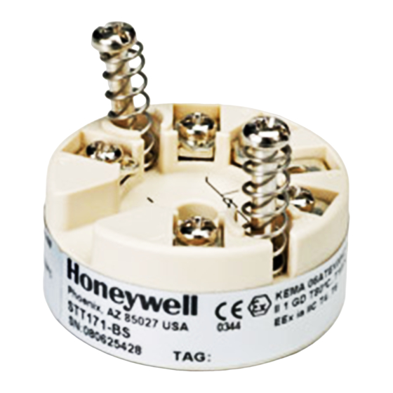
English Figure 4-1 Model STT17H-BS ® 1. 2-WIRE TRANSMITTER WITH HART [FM Installation Drawing] ......25 PROTOCOL MODEL STT17H Figure 4-2 Model STT171-BS, STT173-BS and STT17H-BS [Connections with separate power supply and receiver] ..27 Figure 4-3 Model STT171-BS, STT173-BS and 1.1 Features STT17H-BS [Connections with power •... -
Seite 8: Installation
English English 1.4 Installation 1.5 Electrical Connections Input: RTD, 2-wire RTD, 3-wire RTD, 4-wire TC, internal CJC TC, external CJC Resistance, 2-wire Resistance, 3-wire TC, difference TC, difference RTD, difference or average, or average, Resistance, 4-wire or average with internal CJC with external CJC mV, difference Output:... -
Seite 9: Block Diagram
The STT17H can be configured in the following ways: • With STT17C. • With a HART ® communicator with Honeywell’s DDL Driver (Figure 1-5). STT17C • For programming, please refer to Figure 1-4 and the help function in STT17C. •... -
Seite 10: Connection Of Transmitters In Multi-Drop Mode
For programming, please refer to Figure 1-5. To gain access to across AB or BC (See Figure 1 6). product specific commands, the HART ® communicator must be loaded with the Honeywell’s DDL driver. This can be ordered either at the HART ® Communication Foundation or at Honeywell. STT17H... -
Seite 11: Mechanical Specifications
English Française 1.9 Mechanical Specifications 2. TRANSMETTEUR 2-FILS AVEC ® PROTOCOLE HART STT17H 2.1 Caractères • Entrée RTD, TC, Ohm, ou mA • Très grande précision de mesure ® • Communication avec protocole HART • Isolation galvanique • Pour tête de sonde DIN B 2.2 Application d 6 mm •... -
Seite 12: Installation
Française Française 2.4 Installation 2.5 Connexions Entrée : RTD, 2-fils RTD, 3-fils RTD, 4-fils TC, CSF interne TC, CSF externe Résistance, 2-fils Résistance, 3-fils TC, différence TC, différence RTD, différence ou moyen ou moyen ou moyen avec CSF interne avec CSF externe Résistance, 4-fils mV, différence Sortie :... -
Seite 13: Schema De Principe
• Avec le kit de programmation STT17C ® • Avec le communicateur HART chargé avec le DDL de Honeywell. STT17C • Pour le raccordement du STT17C, veuillez vous reporter au schéma ci-dessous et à l’aide en ligne du logiciel. •... -
Seite 14: Raccordement Des Transmetteurs En Multi-Addressage
Pour avoir accès à tous les paramètres, le communicateur HART ® Le communicateur HART ou le modem peuvent être connectés sur doit être chargé avec le DDL spécifique de Honeywell. Ce DDL les points AB ou sur les points BC (Figure 2-6). ®... -
Seite 15: Dimensions Mécaniques
Française Deutsch ® 2.9 Dimensions mécaniques 3. 2-DRAHT MESSUMFORMER MIT HART PROTOKOLL STT17H 3.1 Das Unterscheidungsmerkmal Eingang für WTH, TE, Ω oder mV • • Extreme Messgenauigkeit ® • HART Kommunikation • Galvanische Trennung • Für Einbau in Anschlusskopf DIN Form B d 6 mm 3.2 Verwendung 20.2 mm... -
Seite 16: Installation
Deutsch Deutsch 3.4 Installation 3.5 Anschlüsse Eingang: WTH, 2-Leiter WTH, 3-Leiter WTH, 4-Leiter TE, interne CJC TE, externe CJC Widerst., 2-Leiter Widerst., 3-Leiter TE, Differenz TE, Differenz WTH, Differenz oder Mittel, oder Mittel, Widerst., 4-Leiter oder Mittel mit interner CJC mit externer CJC mV, Differenz Ausgang:... -
Seite 17: Blockdiagramm
3.6 Blockdiagramm 3.7 Programmierung STT17H kann in 2 verschiedener Weise programmiert werden: • Mittels STT17C. ® • Mittels HART Datenaustauschgerät mit Honeywell’s DDL- Antrieb. STT17C • Bezüglich Programmierung verweisen wir auf die nachfolgende Zeichnung und die “Hilfe”-Funktion im STT17H. •... -
Seite 18: Hart ® Datenaustauschgerät
Datenaustauschgerät oder ein PC-Modem kann über die Zeichnung. Um Zu-tritt zur Produktspezifischen Kommandos zu Punkte AB oder BC angeschlossen werden. ® bekommen, muss das HART Daten-aus-tauschgerät mit dem DDL-Antrieb von Honeywell ausgestattet sein. Der Antrieb ist von ® HART Communication Foundation oder Honeywell erhältlich. STT17H STT17H... -
Seite 19: Abmessungen
Deutsch Installation Drawings 3.9 Abmessungen 4. INSTALLATION DRAWINGS 4.1 FM Installation Drawing 50016324 4.1.1 Model STT17H-BS Non Hazardous Location Hazardous (Classified) Location Class I,Division1, Groups, A,B,C,D Class I, Zone 0, IIC Associated Apparatus or Barrier with Ambient temperature limits entity Parameters: T4: -40 to + 85 deg. -
Seite 20: The Entity Concept
Installation Drawings Installation Drawings 4.1.2 The Entity Concept 4.2 CSA Installation Drawing 50016326 The Transmitter must be installed according to National Electrical 4.2.1 Model STT171-BS, STT173-BS and STT17H-BS Code (ANSI-NFPA 70). Model STT171-BS, STT173-BS and STT17H-BS transmitters are approved as intrinsically safe in Zone 0 Group IIC or Class Equipment that is FM-approved for intrinsic safety may be I, Division1, Group A,B,C,D when installed according to this connected to barriers based on the ENTITY CONCEPT. -
Seite 21: Atex Installation Data
Installation Drawings Installation Drawings Connections with power supply and barrier built into 4.3 ATEX Installation Data receiver. Output: Standard 4 - 20 mA loop Ex / I.S. appoval STT17H-BN: Transmitter Kema 06ATEX0043 X ..... II 3 GD, T80°C...T105°C Intrinsically safe Power Supply Barrier Parameters. -
Seite 22: Declaration Of Conformity
EN 50281-1-1, EN 50284, EN 60079-0 and EN 60079-15 ATEX certificate: KEMA 06ATEX0043 X (STT17H-BN) ATEX certificate: KEMA 06ATEX0044 X (STT17H-BS) Honeywell Industrial Solutions 2500 West Union Hills Drive Phoenix, Arizona 85027 USA Honeywell International Inc. Industrial Measurement & Control Frederick M. - Seite 23 For more information To learn more about Temperature Transmitters, visit www.honeywellprocess.com Or contact your Honeywell Account Manager Process Solutions Honeywell 1250 W Sam Houston Pkwy S Houston, TX 77042 Honeywell Control Systems Ltd Honeywell House, Skimped Hill Lane Bracknell, England, RG12 1EB...