dunkermotoren BG 65 PI Betriebsanleitung

Verwandte Anleitungen für dunkermotoren BG 65 PI


Inhaltszusammenfassung für dunkermotoren BG 65 PI
- Seite 1 Instruction Manual / Betriebsanleitung BLDC motor with parametrizable motion controller integrated Bürstenloser DC-Motor mit integriertem parametrierbarem Motioncontroller BG 65 PI Edition / Ausgabe (05/2010)
-
Seite 2: Inhaltsverzeichnis
10 Software Drive Assistant 10.1 Introduction 10.1 Einführung 10.2 System Requirements 10.2 Systemvoraussetzungen 10.3 Installation of the Software 10.3 Installation der Software Drive Assistant Drive Assistant Instruction Manual/Betriebsanleitung BG 65 PI, Version: 1.4 en_de © 2010 Dunkermotoren GmbH; D-79848 Bonndorf; Germany... - Seite 3 „Ramps [ms / 1000rpm]“ 13.4.4 “Motor Power” Parameter Group 13.4.4 Parametergruppe „Motor power“ 13.4.5 „Homing“ Parameter Group 13.4.5 Parametergruppe „Homing“ 13.4.6 “Positions” Parameter Group 13.4.6 Parametergruppe „Positions“ Instruction Manual/Betriebsanleitung BG 65 PI, Version: 1.4 en_de © 2010 Dunkermotoren GmbH; D-79848 Bonndorf; Germany...
- Seite 4 14.4 Scope of delivery and accessories 14.4 Lieferumfang und Zubehör 14.5 Download PDF-Data 14.5 Download PDF-Daten 15 Anhang 15 Anhang A) CE-Herstellererklärung A) CE-declaration of the manufacturer Instruction Manual/Betriebsanleitung BG 65 PI, Version: 1.4 en_de © 2010 Dunkermotoren GmbH; D-79848 Bonndorf; Germany...
-
Seite 5: About This Document
Einstellungen und helfen certain settings and help you use the Ihnen, den optimalen Nutzen aus dem device to the best possible effect. Gerät zu ziehen. NOTICE HINWEIS Instruction Manual/Betriebsanleitung BG 65 PI, Version: 1.4 en_de © 2010 Dunkermotoren GmbH; D-79848 Bonndorf; Germany... -
Seite 6: General Description
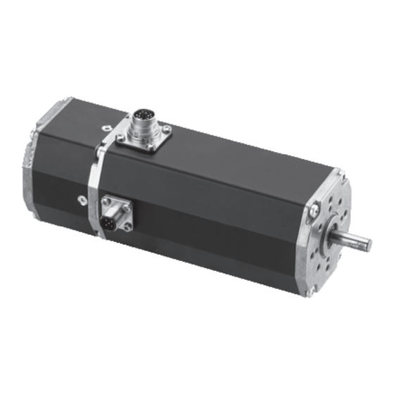
Trägheitsmoment und des robusten construction. Aufbaus. On request, motors in the BG 65 PI range can be com- Die Motoren BG 65 PI können auf Wunsch auch mit bined with planetary or worm gears, which are availa- Planeten-, oder Schneckengetrieben mit einer Vielzahl ble in a very wide range of reduction ratios. - Seite 7 Power and control electronics optional attached brake integrated Motor Parametrierschnittstelle Parametrization interfacae Antriebswelle, Hallsensoren (integriert) optional angebautes Getriebe Hall sensors integrated output shaft, optional attached gearbox Instruction Manual/Betriebsanleitung BG 65 PI, Version: 1.4 en_de © 2010 Dunkermotoren GmbH; D-79848 Bonndorf; Germany...
-
Seite 8: Explanations Of Terms Used
Auch “Current Mode”, Dreh- Torque mode Torque Mode to as “Current Mode” momentregelung Trajektorie Bewegungsablauf Trajectory Sequence of motions Velocity Mode Drehzahlregelung Velocity mode Speed regulation Instruction Manual/Betriebsanleitung BG 65 PI, Version: 1.4 en_de © 2010 Dunkermotoren GmbH; D-79848 Bonndorf; Germany... -
Seite 9: Proper Use
3.3 Proper use Bestimmungsmäßige Verwendung - The BG 65 PI is a vendor part and may be used - Der BG 65 PI ist ein Zulieferteil und darf in der in the configuration described in machines and plant beschriebenen Konfiguration in Maschinen und (industrial sector). -
Seite 10: Safety Instructions
► z.B. (See technical data) (Siehe technische Daten) Transport the drive under storage Transportieren Sie die Antriebe unter conditions Lagerbedingungen: protection against shock ► stoßgeschützt ► Instruction Manual/Betriebsanleitung BG 65 PI, Version: 1.4 en_de © 2010 Dunkermotoren GmbH; D-79848 Bonndorf; Germany... -
Seite 11: Technical Data, Accessories
Antrieb in einer Um- environment which calls for IP65. gebung entsprechend IP65 eingesetzt werden. Instruction Manual/Betriebsanleitung BG 65 PI, Version: 1.4 en_de © 2010 Dunkermotoren GmbH; D-79848 Bonndorf; Germany... -
Seite 12: Motor Installation Drawing
65x65 mm, 160 mm long Dimensions (without (with incremental Abmessungen 65x65 mm, 160 mm lang connector) encoder) (ohne Stecker) (mit Inkrementalgeber) Weight Ca. 1050 g Gewicht ca. 1050 g Instruction Manual/Betriebsanleitung BG 65 PI, Version: 1.4 en_de © 2010 Dunkermotoren GmbH; D-79848 Bonndorf; Germany... -
Seite 13: Motor Bg 65X50 Pi
105 x 105 x 10 bei Anbringung einer thermisch leitenden Stahlplatte mm attached to the motor. der Größe 105 x 105 x 10 mm aufgeführt. Instruction Manual/Betriebsanleitung BG 65 PI, Version: 1.4 en_de © 2010 Dunkermotoren GmbH; D-79848 Bonndorf; Germany... -
Seite 14: Optional Attachments
For larger projects brushless DC motors in the BG 65 Für größere Projekte können Motoren der Baureihen BG 65 mit angebauten Absolutwertgebern ausgestattet range can be fitted with an attached absolut encoder. werden. Instruction Manual/Betriebsanleitung BG 65 PI, Version: 1.4 en_de © 2010 Dunkermotoren GmbH; D-79848 Bonndorf; Germany... -
Seite 15: Accessories
Parametrierung für folgende Betriebsarten: - Current/torque mode - Current/torque mode - Velocity mode - Velocity mode - Position mode - Position mode - SVEL mode - SVEL mode Instruction Manual/Betriebsanleitung BG 65 PI, Version: 1.4 en_de © 2010 Dunkermotoren GmbH; D-79848 Bonndorf; Germany... -
Seite 16: Übertemperaturschutz
/1000Ohm) is used. (z.B. 1kOhm, Verlustleistung >U /1000Ohm) empfohlen. The BG 65 PI motors have an integral ballast circuit, Die Motoren BG 65 PI haben eine integrierte Ballast- which shorts the input voltage through a 2.2 Ohm bal- schaltung, die bei Spannungsüberhöhungen >50V die last resistor if it rises by >50V. -
Seite 17: Current Limitation
Dauerbetrieb zu erreichen, können die Stromparameter system to suit the drive situation. dynamisch vom Mastersystem der Antriebssituation angepaßt werden. Instruction Manual/Betriebsanleitung BG 65 PI, Version: 1.4 en_de © 2010 Dunkermotoren GmbH; D-79848 Bonndorf; Germany... -
Seite 18: Installation/ Terminal Assignment
8.2. Electro-magnetic compatibility Beim Antrieb BG 65 PI und bei der Maschine, in welche The BG 65 PI drive and the machine in which it is installed der Antrieb eingebaut wird, entstehen elektromagne- give rise to the radiation of electromagnetic interference. -
Seite 19: Protective Earth Connection
• This cable must be connected to the flange with a screw. • Hierzu wird das Kabel mit einer Schraube im Flansch • Please avoid touching the connector pins. befestigt. • Bitte die Steckerpins nicht berühren Instruction Manual/Betriebsanleitung BG 65 PI, Version: 1.4 en_de © 2010 Dunkermotoren GmbH; D-79848 Bonndorf; Germany... -
Seite 20: Motor Power Supply And Signal Interface Supply
Logik / Logic +24...(42) V DC GND (0V) Lead colours refers to standard connection cables of Litzenfarben beziehen sich auf Standard Anschlusslei- Dunkermotoren. tungen von Dunkermotoren. Instruction Manual/Betriebsanleitung BG 65 PI, Version: 1.4 en_de © 2010 Dunkermotoren GmbH; D-79848 Bonndorf; Germany... - Seite 21 **In3 und In4 sind im Geschwindigkeits- oder **In3 and In4 are also configurable as analogue inputs Stromregelmodus auch als Analogeingänge in the speed and current regulating modes. konfigurierbar. Instruction Manual/Betriebsanleitung BG 65 PI, Version: 1.4 en_de © 2010 Dunkermotoren GmbH; D-79848 Bonndorf; Germany...
-
Seite 22: Schematic Circuit Of The Digital Outputs
Mating connector with cable (please order in addition) Gegenstecker mit Anschlußleitung (bitte mitbestellen): For the BG 65 PI motors with side-mounted 12-pin con- Für die Motoren BG 65 PI mit seitlichem 12-poligem nector, pre-assembled connection cables are available in a Anschlußstecker stehen passende, vorkonfektionierte... -
Seite 23: Maximum Cable Length And Power Supply
Kabellänge* Kabel nung [V] Kabellänge BG65 (SI, PI, CI, MI) 21,6 27573 35530 27573 35532 24,0 * Can be ordered at Dunkermotoren/ bestellbar bei Dunkermotoren Instruction Manual/Betriebsanleitung BG 65 PI, Version: 1.4 en_de © 2010 Dunkermotoren GmbH; D-79848 Bonndorf; Germany... -
Seite 24: Parametrization Connector
Interface vom PC zum Motor dar. Er wird an den USB-Port und an den 5-poligen Motorstecker the USB port and the 5-pole motor plug. angeschlossen. Instruction Manual/Betriebsanleitung BG 65 PI, Version: 1.4 en_de © 2010 Dunkermotoren GmbH; D-79848 Bonndorf; Germany... -
Seite 25: Connection Schematic
Kabeln zu führen. Werden die von Dunkermotoren must be spaciously applied inside the control verfügbaren Standardkabel verwendet, so ist die cabinet. Schirmung im Schaltschrank breitflächig aufzulegen. Instruction Manual/Betriebsanleitung BG 65 PI, Version: 1.4 en_de © 2010 Dunkermotoren GmbH; D-79848 Bonndorf; Germany... -
Seite 26: Schematic Circuit For Power Supply Controller/ Motor Bg65 Pi
Prinzipschaltbilder für die Spannungsversorgung (BG 45, BG65, BG75). (Regler/ Motoren) der entsprechenden Motorvarianten (BG 45, 65, BG75) in den jeweiligen Bedienungsanlei- tungen beachtet werden. Instruction Manual/Betriebsanleitung BG 65 PI, Version: 1.4 en_de © 2010 Dunkermotoren GmbH; D-79848 Bonndorf; Germany... -
Seite 27: Software Drive Assistant
Installation ein Warnhin- startet by the desktop link. weis bezüglich dem USB-Controller erscheint. Nach erfolgreicher Installation kann der Drive Assistant über die Desktop-Verknüpfung geöffnet werden. Instruction Manual/Betriebsanleitung BG 65 PI, Version: 1.4 en_de © 2010 Dunkermotoren GmbH; D-79848 Bonndorf; Germany... -
Seite 28: Description Of The Main Window
Mit „Options“ kann die Sprache der Hilfetexte geän- the help text. With „Exit“ the user leaves the program. dert werden. Mit „Exit“ verlässt der Anwender das Programm. Instruction Manual/Betriebsanleitung BG 65 PI, Version: 1.4 en_de © 2010 Dunkermotoren GmbH; D-79848 Bonndorf; Germany... -
Seite 29: Description Of The Project Window
Zusätzlich besteht die Möglichkeit, sich über „About…“ “About…” the detailed version data. die ausführliche Versionsdaten anzeigen zu lassen. 12 Description of the 12 Beschreibung des Project Window Projektfensters Instruction Manual/Betriebsanleitung BG 65 PI, Version: 1.4 en_de © 2010 Dunkermotoren GmbH; D-79848 Bonndorf; Germany... -
Seite 30: Description Of The General Paramter Groups - Project Window
Nach der Übertragung muss die Spannung kurz vom Only then is the motor ready for operation. Motor getrennt werden. Erst dann ist der Motor be- triebsbereit. Instruction Manual/Betriebsanleitung BG 65 PI, Version: 1.4 en_de © 2010 Dunkermotoren GmbH; D-79848 Bonndorf; Germany... - Seite 31 Ausgänge werden rot angezeigt. The example below shows the indicator states for the Im Folgenden wird beispielhaft ein Zustand des Anzei- “I/O” screen. ge-Panels „I/O“ gezeigt. Instruction Manual/Betriebsanleitung BG 65 PI, Version: 1.4 en_de © 2010 Dunkermotoren GmbH; D-79848 Bonndorf; Germany...
-
Seite 32: Description Of The File Cards
The specific description of these operating modes are Die genaue Beschreibung dieser Betriebsarten erfolgt carried out under chapter 12. unter Kapitel 12. Instruction Manual/Betriebsanleitung BG 65 PI, Version: 1.4 en_de © 2010 Dunkermotoren GmbH; D-79848 Bonndorf; Germany... -
Seite 33: Description Of The File Card „Drive Parameters
The following filters can be selected: Folgende Filter stehen zur Auswahl: None shows the measuring points in a line diagram. None veraunschaulicht die Messpunkte in einem Liniendiagramm. Instruction Manual/Betriebsanleitung BG 65 PI, Version: 1.4 en_de © 2010 Dunkermotoren GmbH; D-79848 Bonndorf; Germany... -
Seite 34: Description Of The File Card „Device Info
This data makes possible the fischer Daten des Motors. Diese Angaben ermögli- effective support by Dunkermotoren. chen einen effektiven Support durch Dunkermotoren. Instruction Manual/Betriebsanleitung BG 65 PI, Version: 1.4 en_de © 2010 Dunkermotoren GmbH; D-79848 Bonndorf; Germany... -
Seite 35: Description Of The Menu Bar - Project Window
In addition, the possibility exists for displaying with Zusätzlich besteht die Möglichkeit, sich über „About…“ “About…” the detailed contact address of Dunkermo- die ausführliche Kontaktadresse von Dunkermotoren toren. anzeigen zu lassen. Instruction Manual/Betriebsanleitung BG 65 PI, Version: 1.4 en_de © 2010 Dunkermotoren GmbH; D-79848 Bonndorf; Germany... -
Seite 36: Description Of The Operating Modes
Parametergruppen, auf einfache to six positions. Weise bis zu sechs Positionen auf gewünschte Weise anzufahren. Instruction Manual/Betriebsanleitung BG 65 PI, Version: 1.4 en_de © 2010 Dunkermotoren GmbH; D-79848 Bonndorf; Germany... - Seite 37 Homing beginnen Position 1 Position 1 Position 2 Position 2 Position 3 Position 3 Position 4 Position 4 Position 5 Position 5 Position 6 Position 6 Instruction Manual/Betriebsanleitung BG 65 PI, Version: 1.4 en_de © 2010 Dunkermotoren GmbH; D-79848 Bonndorf; Germany...
-
Seite 38: Moving" Parameter Group
In this example, the motor runs at a speed of 2000 In diesem Beispiel läuft der Motor mit der Geschwin- rpm in the clockwise direction. digkeit von 2000 rpm im Uhrzeigersinn. Instruction Manual/Betriebsanleitung BG 65 PI, Version: 1.4 en_de © 2010 Dunkermotoren GmbH; D-79848 Bonndorf; Germany... -
Seite 39: Current [Ma]" Parameter Group
200 ms/1000rpm und eine Bremsrampe mit 200 were configured. For the Quick Stop, 20 ms/1000rpm ms/1000rpm konfiguriert. was defined. Für den Quick Stop wurden 20 ms/1000rpm festge- legt. Instruction Manual/Betriebsanleitung BG 65 PI, Version: 1.4 en_de © 2010 Dunkermotoren GmbH; D-79848 Bonndorf; Germany... -
Seite 40: Motor Power" Parameter Group
Motor muss vor Inbetriebnahme im moved back to the defined stromlosen Zustand manuell in den operating zone with the power definierten Betriebsbereich supply switched off. zurückgeführt werden. Instruction Manual/Betriebsanleitung BG 65 PI, Version: 1.4 en_de © 2010 Dunkermotoren GmbH; D-79848 Bonndorf; Germany... - Seite 41 Überfahren der steigenden Flanke des exact positioning should be performed by driving to Schalters, die genaue Positionierung, durch Anfahren the falling edge. der fallenden Flanke vorgenommen werden soll. Instruction Manual/Betriebsanleitung BG 65 PI, Version: 1.4 en_de © 2010 Dunkermotoren GmbH; D-79848 Bonndorf; Germany...
-
Seite 42: Positions" Parameter Group
Dem Anwender wird ermöglicht komplette Fahrsätze te drive settings with nominal position, acceleration mit Sollposition, Beschleunigungsrampe, Drehzahl ramp, speed and deceleration ramp. und Bremsrampe zu parametrieren. Instruction Manual/Betriebsanleitung BG 65 PI, Version: 1.4 en_de © 2010 Dunkermotoren GmbH; D-79848 Bonndorf; Germany... - Seite 43 über digitale Eingänge, die wie folgt aufgeschlüsselt sind: IN 0 Function IN 0 Funktion Limit switch OFF Limit Schalter AUS Limit switch ON Limit Schalter EIN Instruction Manual/Betriebsanleitung BG 65 PI, Version: 1.4 en_de © 2010 Dunkermotoren GmbH; D-79848 Bonndorf; Germany...
-
Seite 44: Moving" Parameter Group
This is especially significant for the refe- „CCW“ für „counter clockwise“ (gegen den Uhrzeiger- rence run (Homing). sinn). Dies ist besonders für die Referenzfahrt (Ho- ming) von Bedeutung. Instruction Manual/Betriebsanleitung BG 65 PI, Version: 1.4 en_de © 2010 Dunkermotoren GmbH; D-79848 Bonndorf; Germany... -
Seite 45: Homing" Parameter Group
Steigende/Fallende Flanke) zu suchen und sich when it is reached. bei Erreichen den Referenzpunkt zu setzen. Instruction Manual/Betriebsanleitung BG 65 PI, Version: 1.4 en_de © 2010 Dunkermotoren GmbH; D-79848 Bonndorf; Germany... - Seite 46 0.18° ) should entspricht einer Drehung um 0,18° an der Motorab- be assigned to the acquired reference point. triebswelle beim BG65) dem erfassten Referenzpunkt zugewiesen werden soll. Instruction Manual/Betriebsanleitung BG 65 PI, Version: 1.4 en_de © 2010 Dunkermotoren GmbH; D-79848 Bonndorf; Germany...
-
Seite 47: Motor Power" Parameter Group
In diesem Beispiel wurde ein dauerhaft zulässiger rent of 8 A and a peak current of 25 A are defined. Phasenstrom von 8 A und ein Spitzenstrom von 25 A festgelegt. Instruction Manual/Betriebsanleitung BG 65 PI, Version: 1.4 en_de © 2010 Dunkermotoren GmbH; D-79848 Bonndorf; Germany... -
Seite 48: Positions" Parameter Group
01. – 14. sind die Kennnummern der Fahrsätze, die in that can be entered in any field. Positions are given in jedes Feld eingegeben werden können. the “Counts” unit. Instruction Manual/Betriebsanleitung BG 65 PI, Version: 1.4 en_de © 2010 Dunkermotoren GmbH; D-79848 Bonndorf; Germany... -
Seite 49: Stepper" Positioning Mode
Funktion Clear error and Error beseitigen und STOP STOP Begin homing Homing beginnen Position 1 (positive) Position 1 (positiv) Position -1 (negative) Position -1 (negativ) Instruction Manual/Betriebsanleitung BG 65 PI, Version: 1.4 en_de © 2010 Dunkermotoren GmbH; D-79848 Bonndorf; Germany... -
Seite 50: Moving" Parameter Group
In this example, the motor runs with the speed of 500 In diesem Beispiel läuft der Motor mit der Geschwin- rpm in the clockwise direction. digkeit von 500 rpm im Uhrzeigersinn. Instruction Manual/Betriebsanleitung BG 65 PI, Version: 1.4 en_de © 2010 Dunkermotoren GmbH; D-79848 Bonndorf; Germany... -
Seite 51: Current [Ma]" Parameter Group
200 ms/1000rpm und eine Bremsrampe mit 200 were configured. For the Quick Stop, 20 ms/1000rpm ms/1000rpm konfiguriert. was defined. Für den Quick Stop wurden 20 ms/1000rpm festge- legt. Instruction Manual/Betriebsanleitung BG 65 PI, Version: 1.4 en_de © 2010 Dunkermotoren GmbH; D-79848 Bonndorf; Germany... -
Seite 52: Motor Power" Parameter Group
Motor muss vor Inbetriebnahme im moved back to the defined stromlosen Zustand manuell in den operating zone with the power definierten Betriebsbereich supply switched off. zurückgeführt werden. Instruction Manual/Betriebsanleitung BG 65 PI, Version: 1.4 en_de © 2010 Dunkermotoren GmbH; D-79848 Bonndorf; Germany... - Seite 53 Überfahren der steigenden Flanke des exact positioning should be performed by driving to Schalters, die genaue Positionierung, durch Anfahren the falling edge. der fallenden Flanke vorgenommen werden soll. Instruction Manual/Betriebsanleitung BG 65 PI, Version: 1.4 en_de © 2010 Dunkermotoren GmbH; D-79848 Bonndorf; Germany...
-
Seite 54: Positions" Parameter Group
In this example, a positioning with 14000 counts is In diesem Beispiel ist an Kennnummer 01. eine Posi- entered with the identification number 01. tionierung mit 14000 Counts angegeben. Instruction Manual/Betriebsanleitung BG 65 PI, Version: 1.4 en_de © 2010 Dunkermotoren GmbH; D-79848 Bonndorf; Germany... -
Seite 55: Left-Right" Positioning Mode
IN 2 IN 3 Funktion Clear error and Error beseitigen und STOP STOP Begin homing Homing beginnen Position 1 Position 1 Position 2 Position 2 Instruction Manual/Betriebsanleitung BG 65 PI, Version: 1.4 en_de © 2010 Dunkermotoren GmbH; D-79848 Bonndorf; Germany... -
Seite 56: Moving" Parameter Group
In this example, the motor runs with the speed of 500 In diesem Beispiel läuft der Motor mit der Geschwin- rpm in the clockwise direction. digkeit 500 rpm im Uhrzeigersinn. Instruction Manual/Betriebsanleitung BG 65 PI, Version: 1.4 en_de © 2010 Dunkermotoren GmbH; D-79848 Bonndorf; Germany... -
Seite 57: Current [Ma]" Parameter Group
200 ms/1000rpm und eine Bremsrampe mit 200 were configured. For the Quick Stop, 20 ms/1000rpm ms/1000rpm konfiguriert. was defined. Für den Quick Stop wurden 20 ms/1000rpm festge- legt. Instruction Manual/Betriebsanleitung BG 65 PI, Version: 1.4 en_de © 2010 Dunkermotoren GmbH; D-79848 Bonndorf; Germany... -
Seite 58: Motor Power" Parameter Group
Motor muss vor Inbetriebnahme im moved back to the defined stromlosen Zustand manuell in den operating zone with the power definierten Betriebsbereich supply switched off. zurückgeführt werden. Instruction Manual/Betriebsanleitung BG 65 PI, Version: 1.4 en_de © 2010 Dunkermotoren GmbH; D-79848 Bonndorf; Germany... - Seite 59 Überfahren der steigenden Flanke des exact positioning should be performed by driving to Schalters, die genaue Positionierung, durch Anfahren the falling edge. der fallenden Flanke vorgenommen werden soll. Instruction Manual/Betriebsanleitung BG 65 PI, Version: 1.4 en_de © 2010 Dunkermotoren GmbH; D-79848 Bonndorf; Germany...
-
Seite 60: Positions" Parameter Group
In this example, a positioning with 0 counts is en- In diesem Beispiel ist an Kennnummer 01. eine Posi- tered with the identification number 01. tionierung mit 0 Counts angegeben. Instruction Manual/Betriebsanleitung BG 65 PI, Version: 1.4 en_de © 2010 Dunkermotoren GmbH; D-79848 Bonndorf; Germany... -
Seite 61: Modulo" Positioning Mode
über digitale Eingänge, die wie folgt aufgeschlüsselt sind: IN 0 Function IN 0 Funktion Limit switch OFF Limit Schalter AUS Limit switch ON Limit Schalter EIN Instruction Manual/Betriebsanleitung BG 65 PI, Version: 1.4 en_de © 2010 Dunkermotoren GmbH; D-79848 Bonndorf; Germany... - Seite 62 Hinter dem Positioniermodus „Modulo“ steht eine viel- that will be explained with the following example of a seitige Funktionsweise, welche am folgenden Beispiel tool changer. eines Werkzeugwechslers erläutert wird. Instruction Manual/Betriebsanleitung BG 65 PI, Version: 1.4 en_de © 2010 Dunkermotoren GmbH; D-79848 Bonndorf; Germany...
- Seite 63 Ein Motor mit der Einstellung „nur in negativer Dreh- direction of rotation (“-”)” setting requires more than richtung („-“) ansteuern“ benötigt jedoch mehr als eine three-quarters of a revolution. dreiviertel Umdrehung. Instruction Manual/Betriebsanleitung BG 65 PI, Version: 1.4 en_de © 2010 Dunkermotoren GmbH; D-79848 Bonndorf; Germany...
-
Seite 64: Moving" Parameter Group
In diesem Beispiel wurde ein dauerhaft zulässiger rent of 8 A and a peak current of 25 A are defined. Phasenstrom von 8 A und ein Spitzenstrom von 25 A festgelegt. Instruction Manual/Betriebsanleitung BG 65 PI, Version: 1.4 en_de © 2010 Dunkermotoren GmbH; D-79848 Bonndorf; Germany... -
Seite 65: Ramps [Ms / 1000Rpm]" Parameter Group
After STOP regelt das Verhalten nach einem Stop- command. Befehl. After MOVE regulates the behaviour after being dri- After MOVE regelt das Verhalten nach dem Anfahren ven to a position. einer Position. Instruction Manual/Betriebsanleitung BG 65 PI, Version: 1.4 en_de © 2010 Dunkermotoren GmbH; D-79848 Bonndorf; Germany... -
Seite 66: Homing" Parameter Group
Schalter (charakterisiert durch edge) and to set the reference point when it is rea- Steigende/Fallende Flanke) zu suchen und sich bei ched. Erreichen den Referenzpunkt zu setzten. Instruction Manual/Betriebsanleitung BG 65 PI, Version: 1.4 en_de © 2010 Dunkermotoren GmbH; D-79848 Bonndorf; Germany... - Seite 67 0.18° ) should entspricht einer Drehung um 0,18° an der Motorab- be assigned to the acquired reference point. triebswelle beim BG65) dem erfassten Referenzpunkt zugewiesen werden soll. Instruction Manual/Betriebsanleitung BG 65 PI, Version: 1.4 en_de © 2010 Dunkermotoren GmbH; D-79848 Bonndorf; Germany...
-
Seite 68: Positions" Parameter Group
Positions are given in in jedes Feld eingegeben werden können. Positionen the “Counts” unit. werden in der Einheit „Counts“ angegeben. Instruction Manual/Betriebsanleitung BG 65 PI, Version: 1.4 en_de © 2010 Dunkermotoren GmbH; D-79848 Bonndorf; Germany... -
Seite 69: Positioning By Event" Positioning Mode
Projektes auf den Motor werden alle project will reset all motor‘s settings. bisherigen Einstellungen gelöscht. The motor will be freely rotatable. Der Motor ist nun frei bewegbar. NOTICE HINWEIS Instruction Manual/Betriebsanleitung BG 65 PI, Version: 1.4 en_de © 2010 Dunkermotoren GmbH; D-79848 Bonndorf; Germany... - Seite 70 Fehler oder keine Freigabe (IN4=0) (IN4=0) Nor Error, Target reached or Kein Fehler, in Position oder stopped gestoppt Not used Nicht benutzt No Error, Moving Kein Fehler, Bewegung Instruction Manual/Betriebsanleitung BG 65 PI, Version: 1.4 en_de © 2010 Dunkermotoren GmbH; D-79848 Bonndorf; Germany...
-
Seite 71: Moving" Parameter Group
In diesem Beispiel wird die Position nach einem STOP however, after MOVE the motor is given freedom of gehalten, nach MOVE behält der Motor jedoch seine movement. Bewegungsfreiheit. Instruction Manual/Betriebsanleitung BG 65 PI, Version: 1.4 en_de © 2010 Dunkermotoren GmbH; D-79848 Bonndorf; Germany... -
Seite 72: Current [Ma]" Parameter Group
Beschleunigungswert. In this example, the Quick Stop was defined with 50 In diesem Beispiel wurde für den Quick Stop ms/1000rpm. 50 ms/1000rpm festgelegt. Instruction Manual/Betriebsanleitung BG 65 PI, Version: 1.4 en_de © 2010 Dunkermotoren GmbH; D-79848 Bonndorf; Germany... -
Seite 73: Move" Parameter Group
Acceleration („Acc.“) erlaubt die Einstellung der acceleratio ramp Beschleunigungsrampe. Deceleration („Dec.“) allows the setting of the brake Deceleration („Dec.“) erlaubt die Einstellung der ramp. Bremsrampe. Instruction Manual/Betriebsanleitung BG 65 PI, Version: 1.4 en_de © 2010 Dunkermotoren GmbH; D-79848 Bonndorf; Germany... -
Seite 74: Velocity Standard" Velocity Mode
Quick stop, deactivate and Quickstop, deaktivieren und Error eliminate error beseitigen CCW – counter clockwise CCW – gegen den Uhrzeigersinn CW – clockwise CW – mit dem Uhrzeigersinn Instruction Manual/Betriebsanleitung BG 65 PI, Version: 1.4 en_de © 2010 Dunkermotoren GmbH; D-79848 Bonndorf; Germany... -
Seite 75: Velocity Source" Parameter Group
Zu diesem Zweck werden zunächst drei ted or changed via assigned inputs. Geschwindigkeiten eingestellt, welche dann über zugewiesene Eingänge angesteuert bzw. gewechselt werden. Instruction Manual/Betriebsanleitung BG 65 PI, Version: 1.4 en_de © 2010 Dunkermotoren GmbH; D-79848 Bonndorf; Germany... -
Seite 76: Current [Ma]" Parameter Group
In der Parametergruppe „Ramps [ms / 1000rpm]“ kann der Anwender nun diese Rampen nach seinen Bedürfnissen anpassen. Instruction Manual/Betriebsanleitung BG 65 PI, Version: 1.4 en_de © 2010 Dunkermotoren GmbH; D-79848 Bonndorf; Germany... -
Seite 77: Velocity Multi" Velocity Mode
Möglichkeit, modispezifische Parametereinstel- ments to the motor with the aid of the parameterising lungen auf den Motor zu laden. interface. Instruction Manual/Betriebsanleitung BG 65 PI, Version: 1.4 en_de © 2010 Dunkermotoren GmbH; D-79848 Bonndorf; Germany... - Seite 78 Stopped and motor freely rotatable Motor frei drehbar In the following, all configurable parameter groups are Im Folgenden finden sie alle konfigurierbaren Para- described in detail: metergruppen ausführlich beschrieben: Instruction Manual/Betriebsanleitung BG 65 PI, Version: 1.4 en_de © 2010 Dunkermotoren GmbH; D-79848 Bonndorf; Germany...
-
Seite 79: Velocity Source" Parameter Group
über zugewiesene Eingänge angesteuert bzw. ge- wechselt werden können. In this example, the velocities are activated via digital In diesem Beispiel werden die Geschwindigkeiten inputs. über digitale Eingänge angesteuert. Instruction Manual/Betriebsanleitung BG 65 PI, Version: 1.4 en_de © 2010 Dunkermotoren GmbH; D-79848 Bonndorf; Germany... -
Seite 80: Current [Ma]" Parameter Group
200 ms/1000rpm und eine Bremsrampe mit 200 were configured. For the Quick Stop, 20 ms/1000rpm ms/1000rpm konfiguriert. was defined. Für den Quick Stop wurden 20 ms/1000rpm festge- legt. Instruction Manual/Betriebsanleitung BG 65 PI, Version: 1.4 en_de © 2010 Dunkermotoren GmbH; D-79848 Bonndorf; Germany... -
Seite 81: Current Standard" Torque Mode
Die Ansteuerung der Einstellungen erfolgt hierbei über gue or a digital input that is coded as follows: einen anlogen Eingang oder digitale Eingänge, die wie folgt aufgeschlüsselt sind: Instruction Manual/Betriebsanleitung BG 65 PI, Version: 1.4 en_de © 2010 Dunkermotoren GmbH; D-79848 Bonndorf; Germany... -
Seite 82: Current Source" Parameter Group
The analogue operating mode excludes the use of the Ein analoger Betriebsmodus schließt die Verwendung digital operating mode and conversely! des digitalen Betriebsmodus aus und umgekehrt! Instruction Manual/Betriebsanleitung BG 65 PI, Version: 1.4 en_de © 2010 Dunkermotoren GmbH; D-79848 Bonndorf; Germany... -
Seite 83: Velocity [Rpm]" Parameter Group
1000 Umdrehungen pro Minute) angegeben. ramps to his needs. In der Parametergruppe „Ramps [ms / 1000rpm]“ kann der Anwender nun diese Rampen nach seinen Bedürfnissen anpassen. Instruction Manual/Betriebsanleitung BG 65 PI, Version: 1.4 en_de © 2010 Dunkermotoren GmbH; D-79848 Bonndorf; Germany... -
Seite 84: Current Multi" Torque Mode
Möglichkeit, modispezifische Parametereinstel- ments to the motor with the aid of the parameterising lungen auf den Motor zu laden. interface. Instruction Manual/Betriebsanleitung BG 65 PI, Version: 1.4 en_de © 2010 Dunkermotoren GmbH; D-79848 Bonndorf; Germany... - Seite 85 Stopped and motor freely rotatable Motor frei drehbar In the following, all configurable parameter groups are Im Folgenden finden sie alle konfigurierbaren Para- described in detail: metergruppen ausführlich beschrieben: Instruction Manual/Betriebsanleitung BG 65 PI, Version: 1.4 en_de © 2010 Dunkermotoren GmbH; D-79848 Bonndorf; Germany...
-
Seite 86: Current Source" Parameter Group
Eingänge angesteuert bzw. gewechselt werden. In this example, the torque is regulated via digital In diesem Beispiel ist wird das Moment über digitale inputs. Eingänge geregelt. Instruction Manual/Betriebsanleitung BG 65 PI, Version: 1.4 en_de © 2010 Dunkermotoren GmbH; D-79848 Bonndorf; Germany... -
Seite 87: Velocity [Rpm]" Parameter Group
200 ms/1000rpm und eine Bremsrampe mit 300 were configured. For the Quick Stop, 20 ms/1000rpm ms/1000rpm konfiguriert. was defined. Für den Quick Stop wurden 20 ms/1000rpm festge- legt. Instruction Manual/Betriebsanleitung BG 65 PI, Version: 1.4 en_de © 2010 Dunkermotoren GmbH; D-79848 Bonndorf; Germany... -
Seite 88: Maintenance & Service
Getriebefett sind die spezifischen Entsorgungs-vor- ensured when disposing of electronic components and schriften und Umweltrichtlinien des jeweiligen Landes gear lubricant. zu beachten. Instruction Manual/Betriebsanleitung BG 65 PI, Version: 1.4 en_de © 2010 Dunkermotoren GmbH; D-79848 Bonndorf; Germany... -
Seite 89: Error Search
Proportionalanteil des Reglers ist Bitte kontaktieren Sie Regelparameter können nicht auf falsch eingestellt Dunkermotoren die Anforderungen der Applikation eingestellt werden Instruction Manual/Betriebsanleitung BG 65 PI, Version: 1.4 en_de © 2010 Dunkermotoren GmbH; D-79848 Bonndorf; Germany... -
Seite 90: Service & Support
E-Mail: info@dunkermotoren.de E-Mail: info@dunkermotoren.de 14.4 Scope of delivery and accessories 14.4 Lieferumfang und Zubehör As quoted Wie angeboten 14.5 Download PDF-Data 14.5 Download PDF-Daten www.dunkermotoren.de www.dunkermotoren.de Instruction Manual/Betriebsanleitung BG 65 PI, Version: 1.4 en_de © 2010 Dunkermotoren GmbH; D-79848 Bonndorf; Germany... -
Seite 91: Anhang
Bestimmungen der EG Maschinen-Richtlinie entspricht. Bonndorf, den 23.10.2007, K. Pfendler Bonndorf, 23.10.2007, K. Pfendler (Leiter Entwicklung / Konstruktion) (Director Construction / Development) Instruction Manual/Betriebsanleitung BG 65 PI, Version: 1.4 en_de © 2010 Dunkermotoren GmbH; D-79848 Bonndorf; Germany... - Seite 92 Notes Notizen Instruction Manual/Betriebsanleitung BG 65 PI, Version: 1.4 en_de © 2010 Dunkermotoren GmbH; D-79848 Bonndorf; Germany...
- Seite 93 Notes Notizen Instruction Manual/Betriebsanleitung BG 65 PI, Version: 1.4 en_de © 2010 Dunkermotoren GmbH; D-79848 Bonndorf; Germany...
- Seite 94 Notes Notizen Instruction Manual/Betriebsanleitung BG 65 PI, Version: 1.4 en_de © 2010 Dunkermotoren GmbH; D-79848 Bonndorf; Germany...
- Seite 95 Notes Notizen Instruction Manual/Betriebsanleitung BG 65 PI, Version: 1.4 en_de © 2010 Dunkermotoren GmbH; D-79848 Bonndorf; Germany...
-
Seite 96: Vertretungen Und Vertriebsgesellschaften
Tel. +1 310 323 1996 · Fax +1 310 538 9772 Corso Sempione, 221 · I-20025 Legnano MI dee.chatterjee@dunkermotoren.com Tel. +39 0331-596165 · Fax +39 0331-455086 sales.it@dunkermotoren.com Dunkermotoren GmbH Allmendstraße 11 · D-79848 Bonndorf/Schwarzwald www.dunkermotoren.com · info@dunkermotoren.de · Phone +49 (0) 7703 930-0 · Fax +49 (0) 7703 930-210/212...