Inhaltsverzeichnis
Werbung
Verfügbare Sprachen
Verfügbare Sprachen
Quicklinks
BEDIENUNGSANWEISUNG
mit Montageanweisungen
INSTRUCTION FOR USE
and installation
F
NL
D
GB
I
E
P
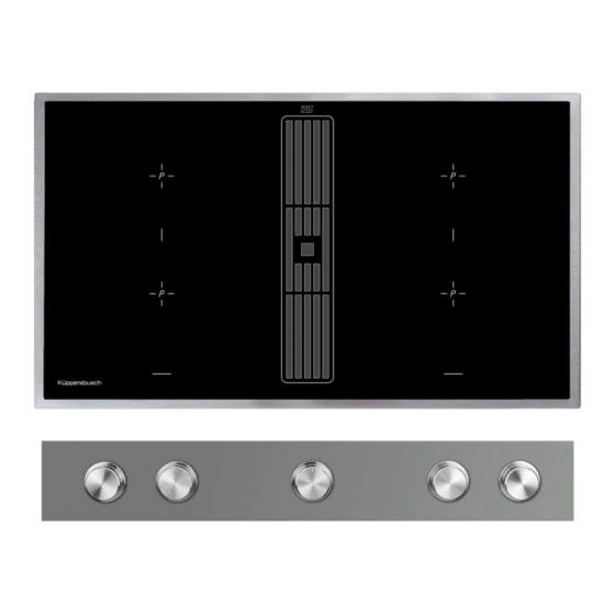
KMI9850.0
Lesen Sie unbedingt die Gebrauchsanleitung
und den Montageplan vor Aufstellung,
Installation sowie Inbetriebnahme.
Please read the users an installation
instructions carefully before installation ot the
appliance and before starting to use.
Service und Kundendienst
Telefon: 0209 - 401 631
Email: kundendienst@kueppersbusch.de
240 651 0000 JA1
Werbung
Kapitel
Inhaltsverzeichnis

Verwandte Anleitungen für Küppersbusch KMI9850.0


Inhaltszusammenfassung für Küppersbusch KMI9850.0
- Seite 1 BEDIENUNGSANWEISUNG mit Montageanweisungen INSTRUCTION FOR USE and installation KMI9850.0 Lesen Sie unbedingt die Gebrauchsanleitung und den Montageplan vor Aufstellung, Installation sowie Inbetriebnahme. Please read the users an installation instructions carefully before installation ot the appliance and before starting to use.
-
Seite 2: Inhaltsverzeichnis
Inhalt 1 Allgemein ..............3 6 Was tun bei Problemen? ...........16 1.1 Küppersbusch-Kundendienst ........3 7 Montageanleitung ............17 1.2 Garantiebedingungen ..........4 7.1 Sicherheitshinweise für 1.3 Hier fi nden Sie............4 den Küchenmöbelmonteur ........17 1.4 Bestimmungsgemäße Verwendung ......4 7.2 Belüftung ..............17 2 Sicherheitshinweise und Warnungen......5 7.3 Einbau ..............17 7.4 Variable Einbaumöglichkeit: 2.1 Für Anschluss und Funktion ........5... -
Seite 3: Allgemein
Allgemein 1 Allgemein Sie erreichen uns: Montag bis Freitag von 8:00 bis 17:00 Uhr 1.1 Küppersbusch-Kundendienst Außerhalb der Dienstzeiten teilen Sie uns Ihre Wünsche Zentrale Kundendienst- / Ersatzteilanforderung bitte per Telefax oder Internet unter Deutschland: www.kueppersbusch.at mit. Küppersbusch Hausgeräte GmbH Bitte beachten Sie: Küppersbuschstraße 16 Damit unser Kundendienst Reparaturen sorgfältig vorbe-... -
Seite 4: Garantiebedingungen
Allgemein 1.2 Garantiebedingungen 4. In Fällen, in denen die Nachbesserung fehlschlägt oder von uns abgelehnt wird, liefern wir innerhalb der oben Zusätzlich zu seinen Gewährleistungsansprüchen aus genannten Garantiezeit auf Wunsch des Endabneh- seinem Kaufvertrag mit dem Händler leisten wir dem mers kostenfrei gleichwertigen Ersatz. -
Seite 5: Sicherheitshinweise Und Warnungen
Sicherheitshinweise und Warnungen 2 Sicherheitshinweise und Warnungen • Bei Brüchen, Sprüngen, Rissen oder anderen Beschädigungen an der Glaskeramik besteht 2.1 Für Anschluss und Funktion Stromschlaggefahr. Das Gerät sofort außer • Die Geräte werden nach den einschlägigen Betrieb setzen. Sofort die Haushalts-Siche- Sicherheitsbestimmungen gebaut. -
Seite 6: Für Personen
Sicherheitshinweise und Warnungen • Schalten Sie nach jeder Benutzung im Umluft- • Heiße Töpfe und Pfannen nicht in die Nähe betrieb den Kochfeldabzug für ca. 20 Minuten der Anzeigen verschieben bzw. diese abde- auf eine geringe Stufe oder aktivieren Sie die cken. -
Seite 7: Symbol- Und Hinweiserklärung
Sicherheitshinweise und Warnungen 2.4 Symbol- und Hinweiserklärung Zusätzlich werden an einigen Stellen die folgenden Gefah- rensymbole verwendet: Das Gerät wurde nach aktuellem Stand der Technik gefer- tigt. Dennoch gehen von Maschinen Risiken aus, die sich konstruktiv nicht vermeiden lassen. WARNUNG VOR ELEKTRISCHER Um dem Bediener ausreichende Sicherheit zu gewähr- ENERGIE! leisten, werden zusätzlich Sicherheitshinweise gegeben,... -
Seite 8: Gerätebeschreibung
Gerätebeschreibung 3 Gerätebeschreibung 3.1 Bedienung Das Dekor kann von den Abbildungen abweichen. Die Bedienung des Glaskeramik-Kochfeldes erfolgt durch die Knebel auf der Blende. Sie sind stufenlos und lassen 1. Induktionskochzone vorne sich nach rechts und nach links überdrehen. 2. Induktionskochzone hinten Durch das Überdrehen auf Anschlag werden verschiedene 3. -
Seite 9: Bedienung
Bedienung 4 Bedienung 4.3 Betriebsdauerbegrenzung Das Induktionskochfeld besitzt eine automatische Be- 4.1 Das Induktionskochfeld triebsdauerbegrenzung. Die Kochfl äche ist mit einem Induktionskochfeld ausgestat- Die kontinuierliche Nutzungsdauer jeder Kochzone ist tet. Eine Induktionsspule unterhalb der Glaskeramik-Koch- abhängig von der gewählten Kochstufe (siehe Tabelle). fl... -
Seite 10: Geschirr Für Induktionskochfeld
Bedienung 4.6 Geschirr für Induktionskochfeld 4.7 Energiespartipps Das für die Induktionskochfl äche benutzte Kochgefäß Nachfolgend fi nden Sie einige wichtige Hinweise, um ener- muss aus Metall sein, magnetische Eigenschaften haben giesparend und effi zient mit Ihrem neuen Induktionskoch- und eine ausreichende Bodenfl äche besitzen. feld und dem Kochgeschirr umzugehen. -
Seite 11: Gerät Betriebsbereit Schalten
Bedienung 4.10 Gerät betriebsbereit schalten Mit dem Knebel Lüfter wird das Gerät betriebsbereit geschal- tet. Der Knebel ist sozusagen der Hauptschalter. Es erfolgt zuerst ein Selbst-Test der Steuerung und die Anzeigen leuch- ten kurz auf. Nach dem Ausschalten über diesen Knebel bleibt das Gerät noch ca. -
Seite 12: Eingestellte Ankochautomatik Kochstufe
Bedienung 4.14 Brückenfunktion Die vordere und die hintere Kochzone können für einen Koch- vorgang zusammen geschaltet werden (Brückenfunktion). Dadurch kann großes Geschirr verwendet werden. 1. Zum Einschalten der Brückenfunktion die Knebel der vor- deren und hinteren Kochzone gleichzeitig nach rechts auf Anschlag drehen bis ein Signalton ertönt. -
Seite 13: Warmhaltefunktion
Bedienung 4.16 Warmhaltefunktion Durch die Warmhaltefunktion können fertige Speisen mit einer bestimmten Temperatur warm gehalten werden. Die Kochzone wird mit geringer Leistung betrieben. 1. Den Knebel nach rechts auf die gewünschte Funktion drehen: entspricht ca. 42°C entspricht ca. 70°C entspricht ca. 94°C 120 Min. -
Seite 14: Lüfter Verwenden
Bedienung 4.19 Lüfter verwenden In der Mitte des Kochfeldes befi ndet sich der Lüfter mit dem Abzug nach unten. Vor Inbetriebnahme des Lüfters Glas-Abdeckung vollständig abnehmen. Bei Modellen mit off ener Abdeckung ist ein Abneh men nicht erforderlich. Glas-Abdeckung Wichtig: Die off... -
Seite 15: Reinigung Und Pfl Ege
Reinigung und Pfl ege 5 Reinigung und Pfl ege Kochfeldes, sondern um nicht entfernte und daher einge- brannte Rückstände. • Vor dem Reinigen das Kochfeld ausschalten und ab- Glanzstellen entstehen durch Abrieb des Topfbodens, kühlen lassen. insbesondere bei Verwendung von Kochgeschirr mit Alu- •... -
Seite 16: Was Tun Bei Problemen
Was tun bei Problemen? 6 Was tun bei Problemen? Der Fehlercode E8 wird angezeigt? Fehler am Lüfter rechts oder links. Die Ansaugöff nung ist Unqualifi zierte Eingriff e und Reparaturen am Gerät sind blockiert bzw. abgedeckt oder der Lüfter ist defekt. gefährlich, weil Stromschlag- und Kurzschlussgefahr besteht. -
Seite 17: Montageanleitung
Montageanleitung 7 Montageanleitung 7.3 Einbau Wichtige Hinweise 7.1 Sicherheitshinweise für den Küchenmöbel- monteur • Übermäßige Hitzeentwicklung von unten z.B. von ei- nem Backofen ohne Querstromlüfter ist zu vermeiden. • Furniere, Kleber bzw. Kunststoff beläge der angren- • Wenn bei Einbauherden der Pyrolysebetrieb stattfi ndet, zenden Möbel müssen temperaturbeständig sein (min. -
Seite 18: Variable Einbaumöglichkeit: Aufl Iegender Einbau
Montageanleitung 7.4 Variable Einbaumöglichkeit: aufl iegender 7.5 Variable Einbaumöglichkeit: fl ächenbündiger Einbau Einbau Maße in mm 902+1 860+1 860+1 min.50 min.50 min.50 min.50 Dichtband in die Ecke der Aufl agekante der Arbeitsplatte aufkleben, so dass sich kein Silikonkleber unter das Koch- Mindestabstand zu benachbarten Wänden feld durchdrücken kann. -
Seite 19: Abbildungen Küchenschrank
Montageanleitung 7.6 Abbildungen Küchenschrank Arbeitsplatte 600 mm max.430 ≥335 ≥170 max.430 NW150 NW150 max.300 Abluftauslass links Abluft wahlweise links oder rechts: Die Abluft kann je nach Einbausituation links oder rechts gewählt Abluftauslass rechts werden. Beachten Sie bitte hierzu die nebenste- henden Maße zur optimalen Planung. -
Seite 20: Zusammenbau Abluftsystem
Montageanleitung 7.7 Zusammenbau Abluftsystem Abluftkanal-Komponenten (optional) Die Verbindung zwischen Kochfeld und Lüfter kann mit einem Flexschlauch oder einem Flachkanal erfolgen. Den Flachkanal nach Bedarf in der Länge mit einer Fein- säge kürzen. Variante Variante Flexschlauch Flachkanal Zu Punkt c Achten Sie bei der Verlegung auf eine möglichst stramme und faltenfreie Installation Kürzen Sie hierzu überfl... -
Seite 21: 7-Poliger Stecker Anschluss Lüfter
Montageanleitung 7.8 7-poliger Stecker Anschluss Lüfter 7.9 4-poliger Stecker Anschluss Plasmafi lter (optional) GEFAHR GEFAHR Stromschlaggefahr Stromschlaggefahr Steckverbindung Lüfter muss vor dem Net- zanschluss erfolgen! Steckverbindung Plasma muss vor dem Netzanschluss erfolgen! Vor einem wieder Öff nen der Steckerverbin- dung das Gerät unbedingt stromlos machen. Steckersicherung und Schutzabdeckung darf Der Netzanschluss darf erst erfolgen, wenn nur bei Anschluss des entsprechenden Plas-... -
Seite 22: Einbau Kochmulden Lüfter
Montageanleitung 7.10 Einbau Kochmulden Lüfter 7.11 Einbau Schaltkasten • Das Produkt darf nur von einem zugelassenen Fach- GEFAHR mann unter Beachtung der örtlich geltenden Vorschrif- Stromschlaggefahr ten angeschlossen werden, gleiches gilt für die Ab- Die Steckverbindungen zwischen Schaltkas- luftanschlüsse. Der Installateur ist für die einwandfreie ten und Kochfeld müssen vor dem Netzan- Funktion am Aufstellort verantwortlich! schluss erfolgen! -
Seite 23: Elektrischer Anschluss
Montageanleitung Mutter U-Scheibe Stiftschraube Achsverlängerung Schraube Führungshülse Halteblech Möbelblende Hülse Knebel Stiftschraube Ansicht von hinten ±0,05 ±0,05 Möbelblende Ansicht von hinten ±0,05 ±0,05 -0,1 ±0,05 ±0,05 ±0,05 Sackloch für Schraube Durchgangsloch für Hülse 7.12 Elektrischer Anschluss WARNUNG VOR ELEKTRISCHER ENERGIE! •... -
Seite 24: Technische Daten
Außerbetriebhame, Entsorgung Anschlussleitung werkseitig vorhanden 7.14 Inbetriebnahme • Das Kochfeld ist werkseitig mit einer temperaturbestän- Nach dem Einbau des Feldes und nach dem Anlegen der digen Anschlussleitung ausgestattet. Versorgungsspannung (Netzanschluss) erfolgt zuerst ein Selbst-Test der Steuerung und es wird eine Serviceinfor- •... -
Seite 25: General
General Contents 1 General ................25 7 Instructions for assembly .........38 1.1 For your information..........25 7.1 Safety instructions for kitchen unit fi tters ....38 1.2 Intended use ............25 7.2 Ventilation ..............38 7.3 Installation ..............38 2 Safety Instructions and Warnings ......26 7.4 Variable installation possibilities: 2.1 For connection and operation ........26 Overlying installation ..........39... -
Seite 26: Safety Instructions And Warnings
Safety Instructions and Warnings 2 Safety Instructions and Warnings • There is a risk of electric shocks if the glass ceramic hob develops fractures, cracks, tears 2.1 For connection and operation or damage of any other kind. Immediately • The appliances are constructed in accordance switch off... -
Seite 27: For Persons
Safety Instructions and Warnings • Activate the childproof lock if there are any 2.3 For persons pets in the home which could make contact • These appliances may be used by children with the hob. aged 8 years and over and by persons with physical, sensory or mental impairments or •... -
Seite 28: Explanation For Symbols And Indications
Safety Instructions and Warnings 2.4 Explanation for symbols and indications The following danger symbols are used at some points: The appliance was produced according to state of the art technology. Machines nevertheless give rise to risks which WARNING OF ELECTRICAL ENERGY cannot be constructively avoided. -
Seite 29: Appliance Description
Appliance description 3 Appliance description Operation The decorative design may deviate from the illustrations. The glass ceramic hob is operated with the regulators on the panel. The regulators are continuously adjustable and 1. Front induction cooking zone it is possible to over-twist them to the right and left. 2. -
Seite 30: Operation
Operation 4 Operation 4.3 Operation time limit The induction hob has an automatic time limit function. 4.1 The induction hob The duration of continuous use of each cooking zone de- The hob is equipped with an induction cooking mode. An pends on the cooking level selected (see chart). -
Seite 31: Cookware For Induction Hobs
Operation 4.6 Cookware for induction hobs 4.7 How to cut power consumption Cookware for induction cooking zones must be made of The following are a few useful hints to help you cut your metal and have magnetic properties. The base must be consumption of energy and use your new induction hob suffi... -
Seite 32: Switching The Appliance Into The Standby Mode
Operation 4.10 Switching the appliance into the standby mode This regulator is used to switch the entire hob operational. It is, as it were, the main switch. An automatic test of the cont- rols will be carried out fi rst of all, and the displays will light up briefl... -
Seite 33: Bridging Function
Operation 4.14 Bridging function The front and the rear cooking zones may be activated to- gether for a cooking process (bridging function). This enables larger cookware to be used. 1. Turn the regulators of the front and back cooking zones simultaneously to the right until they stop and a signal sounds. -
Seite 34: Keep-Warm Function
Operation 4.16 Keep-warm function With the keep-warm function you keep food warm with a specifi c temperature. The respective cooking zone is ope- rated at a low power level. 1. Turn the regulator to the right into the required position: corresponds to about 42°C corresponds to about 70°C corresponds to about 94°C... -
Seite 35: Using The Fan
Operation 4.19 Using the fan The fan is located in the middle of the hob with the extractor facing downwards. Remove the glass cover before initial operation of the fan. The cover does not need to be removed from models with an open cover. -
Seite 36: Cleaning And Care
Cleaning and care 5 Cleaning and care Shiny spots result when the base of the cookware rubs on the surface of the hob, particularly when cookware • Switch the hob off and let it cool down before you clean with an aluminium base or unsuitable cleaning agents are used. -
Seite 37: What To Do If Trouble Occurs
What to do if trouble occurs? 6 What to do if trouble occurs? Error code E8 is indicated? Fault on the left or right fan. The suction opening is blo- Interference with and repairs to the appliance by unquali- cked or covered or the fan is defect. fi... -
Seite 38: Instructions For Assembly
Instructions for assembly 7 Instructions for assembly 7.3 Installation Important information 7.1 Safety instructions for kitchen unit fi tters • Avoid excessive thermal development from below e.g. • Veneers, adhesives and plastic surfaces of surrounding from a baking oven without a cross fl ow cooling device. furniture must be temperature resistant (at least 75°C). -
Seite 39: Variable Installation Possibilities: Overlying Installation
Instructions for assembly 7.4 Variable installation possibilities: 7.5 Variable installation possibilities: Overlying installation Flush installation 902+1 Dimensions in mm 860+1 860+1 min.50 min.50 min.50 min.50 Glue the sealing tape onto the corner of the supporting edge of the worktop so that no silicone adhesive can be Minimum distance to adjacent walls pressed under the hob. -
Seite 40: Illustration Cupboard
Instructions for assembly 7.6 Illustration cupboard 600-mm worktop max.430 ≥335 ≥170 max.430 NW150 NW150 max.300 Exhaust outlet on the left Option of outgoing air on the left or right: Depending on installation, left or right can be chosen for outgoing air Exhaust outlet on the right Please note the dimensions shown opposite for optimal planning. -
Seite 41: Extraction Air System Assembly
Instructions for assembly 7.7 Extraction air system assembly Exhaust air duct components (optional): The hob and the fan can be connected with a fl exible hose or a fl at duct. Shorten the fl at duct with a fi ne saw if necessary. Option fl... -
Seite 42: 7-Pole Fan Plug Connector
Instructions for assembly 7.8 7-pole fan plug connector 7.9 4-pole plasma fi lter plug connector (optional) DANGER DANGER Risk of electric shocks Risk of electric shocks The fan plug connection must be made befo- The plasma connection must be made befo- re the mains connection! re the mains connection! The appliance must be cut off... -
Seite 43: Hob Fan Installation
Instructions for assembly 7.10 Hob fan installation 7.11 Built-in switch box • The product may only be connected by a qualifi ed fi tter DANGER according to applicable local regulations. The same Risk of electric shocks applies for the extraction air connections. The fi tter is The connections between switch box and responsible for proper functioning at the installation hob must be made before the mains connec-... -
Seite 44: Electrical Connection
Instructions for assembly Washer Stud bolt Lengthening spindle Screw Guide Sleeve Retaining plate Cupboard cover Sleeve Regulators Stud bolt Rear view Cupboard cover ±0,05 ±0,05 Rear view ±0,05 ±0,05 -0,1 ±0,05 ±0,05 ±0,05 Blind hole for screw Pass hole for sleeve 7.12 Electrical connection •... -
Seite 45: Technical Data
Decommissioning and disposal of the appliance Mains cable available in the factory 7.14 Putting the appliance into operation • The hob has been fi tted with a temperature-resistant Once the hob has been installed and the power supply has connection cable in the factory. been provided (mains connected) an automatic test of the controls will be carried out and information for Customer •... -
Seite 46: General
Généralités Table des matières 1 Généralités ..............46 7 Instructions de montage ...........59 1.1 Ce que vous trouverez ici........46 7.1 Consignes de sécurité pour l’installateur des meubles de cuisine .........59 1.2 Utilisation conforme à l’usage prévu .....46 7.2 Ventilation ..............59 2 Consignes de sécurité... -
Seite 47: Consignes De Sécurité Et Avertissements
Consignes de sécurité et avertissements 2 Consignes de sécurité et avertissements • La surface en vitrocéramique est très résistan- te. Évitez toutefois d’y faire tomber des objets 2.1 Pour le raccordement et le fonctionnement durs. Les impacts en forme de point peuvent •... -
Seite 48: Pour Les Personnes
Consignes de sécurité et avertissements • En mode « Recyclage d'air », cette humidité • Ne jamais poser d'objets (tels que casseroles, des vapeurs de cuisson n'est que très peu torchons, etc.) sur les affi chages ! éliminée. C'est pourquoi il faut toujours veiller •... -
Seite 49: Explication Des Symboles Et Des Consignes
Consignes de sécurité et avertissements 2.4 Explication des symboles et des consignes En outre, les symboles de danger suivants marquent cer- tains passages de texte : L'appareil a été fabriqué selon l'état actuel de la technique. Cependant, les machines recèlent toujours des risques qu'il n'est pas possible d'exclure en matière de constructi- ATTENTION - ÉNERGIE ÉLECTRIQUE ! DANGER DE MORT ! -
Seite 50: Description De L'appareil
Description de l’appareil 3 Description de l’appareil 3.1 Utilisation Le décor peut être diff érent de celui illustré. La commande de la table de cuisson en vitrocéramique est assurée par les boutons sur le bandeau. Ils sont à 1. Zone de cuisson à induction avant réglage progressif et peuvent être tournés vers la droite et 2. -
Seite 51: Utilisation
Utilisation 4 Utilisation 4.3 Limitation de la durée de fonctionnement La table de cuisson à induction possède une limitation 4.1 La table de cuisson à induction automatique de la durée de fonctionnement. La table de cuisson est composée de zones de cuisson à La durée de fonctionnement en continu de chacune des induction. -
Seite 52: Vaisselle Pour Table De Cuisson À Induction
Utilisation 4.6 Vaisselle pour table de cuisson à induction 4.7 Conseils pour économiser de l’énergie Vous trouvez, ci-après, quelques conseils importants Le récipient utilisé avec la table à induction doit être en concernant l’utilisation économique et effi cace de votre métal, avoir des propriétés magnétiques et posséder un nouvelle table de cuisson à... -
Seite 53: Commuter L'appareil Prêt À L'emploi
Utilisation 4.10 Commuter l'appareil prêt à l'emploi Cette manette permet de placer l'appareil en mode Veille, prêt à l'utilisation. Elle s’agit du commutateur principal. Un auto- test de la commande sera d'abord exécuté et les affi chages s'allument brièvement. Après l'arrêt de l'appareil avec cette manette, celui-ci reste encore en état de fonctionnement pendant encore 120 minu- tes environ. -
Seite 54: Fonction De Pontage
Utilisation 4.14 Fonction de pontage La zone de cuisson avant et arrière peuvent être mises en circuit simultanément (fonction de pontage). Ceci permet d’uti- liser des récipients de cuisson plus grands. 1. Pour activer la fonction de pontage, tourner simultanément vers la gauche les boutons des zones de cuisson avant et arrière jusqu'en butée jusqu’à... -
Seite 55: Fonction De Maintien Au Chaud
Utilisation 4.16 Fonction de maintien au chaud Avec la fonction de maintien au chaud , vous pouvez maintenir au chaud un plat cuit sur une zone de cuisson. La zone de cuisson est alors utilisée avec une puissance réduite. 1. Tourner la manette de réglage et positionner-la sur le niveau de puissance désiré. -
Seite 56: Utiliser Le Ventilateur
Utilisation 4.19 Utiliser le ventilateur Le ventilateur, avec évacuation vers le bas, se trouve au centre de la table de cuisson. Retirer entièrement le couvercle en verre avant la mise en service du ventilateur. Le retrait n'est pas nécessaire pour les modèles avec couvercle ouvert en aluminium. -
Seite 57: Nettoyage Et Entretien
Nettoyage et entretien 5 Nettoyage et entretien la plaque vitrocéramique. Il ne s’agit pas d’une altération du matériau mais de restes calcinés qui n’ont pas été • Avant le nettoyage, éteignez la table de cuisson et enlevés. laissez-la refroidir. Des zones brillantes surgissent à la suite du frottement •... -
Seite 58: Que Faire En Cas De Problèmes
Que faire en cas de problèmes ? 6 Que faire en cas de problèmes ? Le code d’erreur E8 s’affi che. Anomalie au niveau de la ventilation droite ou gauche. Les interventions ou réparations non qualifi ées sont L’ouverture d’aspiration est bloquée ou recouverte ou la dangereuses ;... -
Seite 59: Instructions De Montage
Instructions de montage 7 Instructions de montage 7.3 Montage Consignes importantes 7.1 Consignes de sécurité pour l’installateur des meubles de cuisine • Éviter toute production de chaleur excessive sous la table de cuisson, provenant par exemple d'un four sans • Les placages, colles ou revêtements plastiques des ventilation tangentielle. -
Seite 60: Possibilités Variables De Montage : Montage Posé
Instructions de montage 7.4 Possibilités variables de montage : 7.5 Possibilités variables de montage : Montage posé Montage à surface plane Dimensions en mm 902+1 860+1 860+1 min.50 min.50 min.50 min.50 Coller le ruban d’étanchéité dans l’angle de la découpe du plan de travail et ce, de telle sorte que la colle silicone ne Espacement minimal par rapport aux meubles puisse pas pénétrer sous la table de cuisson. -
Seite 61: Illustrations Armoire De Cuisine
Instructions de montage 7.6 Illustrations Armoire de cuisine Plan de travail 600 mm 430 max ≥335 ≥170 430 max NW150 NW150 300 max Sortie d'évacuation d'air à gauche Évacuation d'air au choix à gauche ou à droite : en fonction de la situation de montage, la positi- Sortie d'évacuation d'air à... -
Seite 62: Assemblage Du Système D'évacuation D'air
Instructions de montage 7.7 Assemblage du système d'évacuation d'air Composants du canal d'évacuation (inclus) : Le raccordement de la table de cuisson au ventilateur peut se faire avec une gaine fl exible ou un canal plat. Raccourcir le cas échéant avec une scie fi ne la longueur du canal plat. -
Seite 63: Connecteur 7 Pôles Raccordement Ventilateur
Instructions de montage 7.8 Connecteur 7 pôles Raccordement 7.9 Connecteur 4 pôles Raccordement fi ltre au ventilateur plasma DANGER DANGER Risque d'électrocution ! Risque d'électrocution ! Le branchement du ventilateur doit être réa- Le branchement du plasma doit être réalisés lisés avant le raccordement au réseau ! avant le raccordement au réseau ! Avant toute ouverture du branchement, mett-... -
Seite 64: Ventilateur De Table De Cuisson
Instructions de montage 7.10 Ventilateur de table de cuisson 7.11 Montage du boîtier de commutation • Le produit doit être raccordé uniquement par un pro- DANGER fessionnel dans le respect des prescriptions locales en Risque d'électrocution ! vigueur, ce qui vaut également pour les raccordements Les connexions électriques entre le boîtier d'évacuation. -
Seite 65: Raccordement Électrique
Instructions de montage Écrou Rondelle en U Tige fi letée Rallonge Douille de guidage Tôle de maintien Bandeau de meuble Douille Bouton Tige fi letée Vue de dessous ±0,05 ±0,05 Bandeau de meuble Vue de dessous ±0,05 ±0,05 -0,1 ±0,05 ±0,05 ±0,05 Trou bouché... -
Seite 66: Caractéristiques Techniques
Mise hors service, élimination Appareil livré avec cordon d’alimentation 7.14 Mise en service • La table de cuisson est équipée en usine d'un cordon Une fois la table de cuisson encastrée et branchée (ré- électrique thermorésistant. seau), un auto-test de l’élément de commande est eff ectué et un message destiné... -
Seite 67: Algemene Opmerkingen
Algemene opmerkingen Inhoud 1 Algemene opmerkingen ..........67 7 Montagehandleiding ..........80 1.1 Hier vindt u.............67 7.1 Veiligheidsinstructies voor de keukenmeubelmonteur ..........80 1.2 Reglementair gebruik ..........67 7.2 Ventilatie..............80 2 Veiligheidsaanwijzingen en waarschuwingen ..68 7.3 Montage ..............80 2.1 Voor aansluiting en werking ........68 7.4 Variabele montagemogelijkheden: 2.2 Voor de kookplaat in het algemeen .......68 Opliggende montage ..........81... -
Seite 68: Veiligheidsaanwijzingen En Waarschuwingen
Veiligheidsaanwijzingen en waarschuwingen 2 Veiligheidsaanwijzingen en waarschuwin- • De keramische plaat is zeer stevig. Zorg er niettemin voor dat er geen harde voorwerpen op de keramische plaat vallen. Puntvormige 2.1 Voor aansluiting en werking slagbelastingen kunnen de kookplaat doen • De apparaten worden volgens de geldende breken. -
Seite 69: Voor Personen
Veiligheidsaanwijzingen en waarschuwingen • In circulatiebedrijf wordt het vocht uit de damp • Nooit gesloten conservenblikken en compo- maar voor een klein deel verwijderd. Er moet undverpakkingen op kookzones verwarmen. daarom altijd voor voldoende toevoer van ver- Door de energietoevoer kunnen deze ui- se lucht, worden gezorgd, bijvoorbeeld door teenspatten! een geopend raam of door het gebruik van... -
Seite 70: Symbool- En Instructieverklaring
Veiligheidsaanwijzingen en waarschuwingen 2.4 Symbool- en instructieverklaring Bovendien worden op sommige plekken de volgende gevaarsymbolen gebruikt: Het apparaat werd volgens de huidige stand van de techniek geproduceerd. Desondanks kunnen machines risico's opleveren, die constructief niet te vermijden zijn. WAARSCHUWING VOOR ELEKTRI- Om voldoende veiligheid voor de bediener te waarborgen, SCHE ENERGIE! worden extra veiligheidsinstructies gegeven in de vorm... -
Seite 71: Beschrijving Van Het Toestel
Beschrijving van het toestel 3 Beschrijving van het toestel 3.1 Bediening Het decor kan van de afbeeldingen afwijken. De keramische kookplaat wordt bediend met de knoppen op het paneel. Ze zijn traploos te bedienen en kunnen 1. Inductiekookzone voor zowel rechtsom als linksom worden doorgedraaid. 2. -
Seite 72: Bediening
Bediening 4 Bediening 4.3 Gebruiksduurbeperking De inductiekookplaat bezit een automatische gebruiksdu- 4.1 Het inductiekookveld urbeperking. De kookplaat is met een inductiekookveld uitgerust. Een De ononderbroken gebruiksduur voor elke kookzone is inductiespoel onder de keramische kookplaat wekt een afhankelijk van de gekozen kookstand (zie tabel). elektromagnetisch wisselveld op, dat de vitrokeramiek doordringt en in de bodem van de pan een warmtevor- De voorwaarde is dat tijdens de gebruiksduur de instellin-... -
Seite 73: Servies Voor Inductiekookplaat
Bediening 4.6 Servies voor inductiekookplaat 4.7 Tips om energie te besparen De pannen die voor de inductiekookplaat worden gebru- Hier vindt u enkele belangrijke aanwijzingen om zuinig en ikt, moeten van metaal zijn, magnetische eigenschappen effi ciënt met uw nieuwe inductiekookplaat en uw kookgerei bezitten en een voldoende grote bodem hebben. -
Seite 74: Toestel In Operationele Modus Zetten
Bediening 4.10 Toestel in operationele modus zetten Met de ventilatorknop wordt het toestel in de operationele modus geschakeld. Deze knop is als het ware de hoofdscha- kelaar. Er vindt eerst een zelftest van de besturing plaats en de weergavelampjes gaan kort branden. Na het uitschakelen met deze toets blijft het toestel nog ca. -
Seite 75: Brugfunctie
Bediening 4.14 Brugfunctie De voorste en de achterste kookzone kunnen voor het koken aaneengeschakeld worden (brugfunctie). Daardoor kunnen grote pannen worden gebruikt. 1. Voor het inschakelen van de brugfunctie de knoppen van de voorste en achterste kookzone tegelijkertijd tot de aanslag naar rechts draaien tot een piep klinkt. -
Seite 76: Warmhoudfunctie
Bediening 4.16 Warmhoudfunctie Met de warmhoudfunctie kunnen gerechten die klaar zijn op een kookzone warm gehouden worden. De kookzone wordt met laag vermogen gebruikt. 1. Om de kookzone in te schakelen de regelknop naar rechts op de gewenste stand draaien. komt overeen met ca. -
Seite 77: Ventilator Gebruiken
Bediening 4.19 Ventilator gebruiken In het midden van de kookplaat bevindt zich de ventilator met afzuiging naar onderen. Voor de ingebruikname van de ventilator dient het glazen deksel weggehaald te worden. Bij modellen met een open deksel is weghalen ervan niet ver- eist. -
Seite 78: Reiniging En Onderhoud
Reiniging en onderhoud 5 Reiniging en onderhoud Kleurveranderingen van de kookplaat hebben geen invloed op de werking en de stevigheid van de vitrokera- • Vóór het reinigen de kookplaat uitschakelen en laten miek. Het gaat hierbij niet om een beschadiging van de afkoelen. -
Seite 79: Wat Te Doen Bij Problemen
Wat te doen bij problemen? 6 Wat te doen bij problemen? De foutcode E8 wordt getoond? Fout aan de ventilator rechts of links. De aanzuigopening Ongekwalifi ceerde ingrepen en reparaties aan het appa- is geblokkeerd of afgedekt, of de ventilator is defect. raat zijn gevaarlijk omdat er gevaar voor stroomstoten en kortsluiting bestaat. -
Seite 80: Montagehandleiding
Montagehandleiding 7.3 Montage 7 Montagehandleiding Belangrijke opmerkingen 7.1 Veiligheidsinstructies voor de keukenmeubel- monteur • Overmatige warmteontwikkeling langs onder, bijv. door een oven zonder dwarsstroomventilator, moet worden • Het fi neer, de lijm of de kunststofbekleding van de aan- vermeden. grenzende meubels moeten temperatuurbestendig zijn (min. -
Seite 81: Variabele Montagemogelijkheden: Opliggende Montage
Montagehandleiding 7.4 Variabele montagemogelijkheden: Opliggen- 7.5 Variabele montagemogelijkheden: de montage Randloze montage Afmetingen in mm 902+1 860+1 860+1 min.50 min.50 min.50 min.50 Afdichttape in de hoek van de steunrand van het aanrecht aanbrengen, zodat geen siliconenlijm onder de kookplaat Minimumafstand tot naburige wanden kan terechtkomen. -
Seite 82: Afbeeldingen Keukenkast
Montagehandleiding 7.6 Afbeeldingen keukenkast Werkblad 600 mm max.430 ≥335 ≥170 max.430 NW150 NW150 max.300 Afzuigeruitlaat links Afzuiging naar keuze links of rechts: de afvoer- lucht kan afhankelijk van de inbouwsituatie links Afzuigeruitlaat rechts of rechts gekozen worden. Houd hierbij rekening met de hiernaast vermelde afmetingen voor een optimale planning. -
Seite 83: Montage Afzuigsysteem
Montagehandleiding 7.7 Montage afzuigsysteem Afzuigluchtkanaal-componenten (optioneel): De verbinding tussen kookplaat en ventilator kan met een fl exibele slang of een plat kanaal tot stand worden ge- bracht. Het platte kanaal indien nodig met een fi jne zaag inkorten. Variant fl exibele Variant plat slang kanaal... -
Seite 84: 7-Polige Stekker Aansluiting Ventilator
Montagehandleiding 7.8 7-polige stekker aansluiting ventilator 7.9 4-polige stekker aansluiting plasmafi lter (op- tioneel) GEVAAR GEVAAR Gevaar voor elektrische schokken Gevaar voor elektrische schokken De stekker van de ventilator moet voor de netaansluiting worden ingestoken! De stekker van de plasmafi lter moet voor de netaansluiting worden ingestoken! Voor het opnieuw openen van de stekkerver- binding moet het toestel in elk geval stroom-... -
Seite 85: Montage Kookplaatventilator
Montagehandleiding 7.10 Montage kookplaatventilator 7.11 Inbouw schakelkast • Het product mag alleen door een erkende vakman met GEVAAR inachtneming van de plaatselijk geldende voorschriften Gevaar voor elektrische schokken worden aangesloten; hetzelfde geldt voor de afzui- De stekkerverbinding tussen schakelkast en gingsaansluitingen. -
Seite 86: Elektrische Aansluiting
Montagehandleiding Moer U-schijf Draadeind Asverlenging Schroef Geleidebus Borgplaat Meubelpaneel Knoppen Draadeind Aanzicht van voor ±0,05 ±0,05 Meubelpaneel Aanzicht van voor ±0,05 ±0,05 -0,1 ±0,05 ±0,05 ±0,05 Blind gat voor schroef Doorlaatgat voor bus 7.12 Elektrische aansluiting met een van deze installaties stroomloos maken. WAARSCHUWING VOOR ELEKTRISCHE •... -
Seite 87: Technische Gegevens
Buitenbedrijfstelling, afvoer Aansluitkabel standaard aanwezig 7.14 Inbedrijfstelling • De kookplaat is bij levering met een temperatuurbes- Na het inbouwen van de kookplaat en na het inschakelen tendige aansluitkabel uitgerust. van de voedingsspanning (aansluiting op het net) vindt eerst een zelftest van de besturing plaats en verschijnt er •... -
Seite 88: Linee Generali
Linee generali Contenuto 1 Linee generali .............88 7 Istruzioni di montaggio ...........101 1.1 Qui trovate.............88 7.1 Indicazioni di sicurezza per il montaggio dei mobili da cucina....101 1.2 Utilizzo conforme alla destinazione d’uso .....88 7.2 Ventilazione ............101 2 Indicazioni in materia di sicurezza e avvertenze ..89 7.3 Incasso ..............101 2.1 Per il collegamento e il funzionamento ....89 7.4 Possibilità... -
Seite 89: Indicazioni In Materia Di Sicurezza E Avvertenze
Indicazioni in materia di sicurezza e avvertenze 2 Indicazioni in materia di sicurezza e • La superfi cie in vetroceramica è molto resis- avvertenze tente agli urti. Evitare però che oggetti solidi e duri cadano sulla superfi cie di cottura, perché 2.1 Per il collegamento e il funzionamento potrebbero provocarne la rottura se appuntiti. -
Seite 90: Per Le Persone
Indicazioni in materia di sicurezza e avvertenze • In modalità ventilata, l’umidità del vapore • Non appoggiare mai oggetti (pentole, grasso viene rimossa soltanto in piccola asciugamani ecc.) sugli indicatori! parte. Occorre pertanto provvedere sempre • Le pentole e i tegami caldi non devono coprire a un suffi... -
Seite 91: Spiegazione Dei Simboli E Delle Avvertenze
Indicazioni in materia di sicurezza e avvertenze 2.4 Spiegazione dei simboli e delle avvertenze In più ci si trovano anche i seguenti simboli di pericolo: L'apparecchio è stato costruito secondo lo stato attuale della tecnica. Le macchine comportano tuttavia dei rischi ATTENZIONE! ENERGIA ELETTRICA! che non sono evitabili sotto il profi... -
Seite 92: Descrizione Dell'apparecchio
Descrizione dell'apparecchio 3 Descrizione dell'apparecchio 3.1 I comandi La decorazione del piano può diff erire dalle illustrazioni. L'uso del piano di cottura in vetroceramica avviene tramite i regolatori sul pannello. Sono regolabili senza graduazio- 1. Zona di cottura ad induzione anteriore ne e possono essere girati fuori giro a destra e a sinistra. -
Seite 93: Comandi
I comandi 4 I comandi 4.3 Limitazione della durata d'esercizio Il piano di cottura ad induzione ha un dispositivo automati- 4.1 Il piano di cottura ad induzione co che limita la durata d'esercizio. Il piano di cottura è dotato di un campo di cottura ad indu- La durata di funzionamento di ogni singola zona di cottura zione. -
Seite 94: Pentole Da Utilizzare Per La Cottura Ad Induzione
I comandi 4.6 Pentole da utilizzare per la cottura ad 4.7 Consigli per il risparmio d'energia induzione In seguito vi diamo alcuni consigli su come adoperare il nuovo piano di cottura ad induzione in modo effi cace ed I recipienti utilizzati per la superfi cie di cottura ad induzione economico. -
Seite 95: Mettere L'apparecchio Pronto Per L'uso
I comandi 4.10 Mettere l'apparecchio pronto per l'uso. Con questo regolatore del ventilatore si mette l'apparecchio pronto per l'uso. Questo regolatore è in pratica l'interruttore principale. Viene eseguito per primo un autotest dell'unità di comando, e le indicazioni si accendono brevemente. Dopo lo spegnimento con questo regolatore, l'apparecchio rimane ancora pronto per l'uso per ca. -
Seite 96: Funzione Ponte
I comandi 4.14 Funzione ponte Le zone di cottura anteriore e posteriore possono essere collegate per un processo di cottura (funzione ponte). Cosi è possibile usare stoviglie grosse. 1. Per attivare la funzione ponte, girare a destra fi no all’arres- to contemporaneamente i regolatori delle zone di cottura sinistra e destra, fi... -
Seite 97: Funzione Scaldavivande
I comandi 4.16 Funzione scaldavivande Con questa funzione scaldavivande è possibile mantenere in caldo dei cibi già pronti con una determinata temperatura. La zona di cottura funziona a potenza minima. 1. Girare il regolatore a destra fi no al raggiungimento della funzione desiderata: corrisponde a ca. -
Seite 98: Usare La Cappa Aspirante
I comandi 4.19 Usare la cappa aspirante La cappa aspirante si trova nel centro del piano di cottura con lo scarico verso il basso. Prima di usare il piano di cottura togliere completamente la copertura. Non bisogna rimuoverla nei modelli con copertura in acciaio aperta. -
Seite 99: Pulizia E Manutenzione
Pulizia e manutenzione 5 Pulizia e manutenzione Lo sfregamento dei fondi delle pentole sulla superfi cie potrebbe causare la formazione di aree lucide, special- • Lasciare raff reddare la superfi cie di cottura prima di mente se le pentole sono d’alluminio o se si sono utilizzati procedere alla pulizia. -
Seite 100: Che Fare In Caso Di Problemi
Che fare in caso di problemi? 6 Che fare in caso di problemi? E’ visualizzato il codice d'errore E8? Errore al ventilatore destro o sinistro. L’apertura di aspira- Modifi che e riparazioni all'apparecchio non a regola d’arte zione è bloccata o coperta oppure è difettoso il ventilatore. possono essere pericolose, perché... -
Seite 101: Istruzioni Di Montaggio
Istruzioni di montaggio 7 Istruzioni di montaggio 7.3 Incasso Avvertenze importanti 7.1 Indicazioni di sicurezza per il montaggio dei mobili da cucina • Evitare un eccessivo surriscaldamento inferiore, causato per esempio da forni sprovvisti di ventilatore a • Impiallacciature, collanti o rivestimenti plastici sui mobili corrente trasversale. -
Seite 102: Possibilità Di Montaggio: Incasso Appoggiato
Istruzioni di montaggio 7.4 Possibilità di montaggio: 7.5 Possibilità di montaggio: Incasso appoggiato Incasso per l’incasso a paro Misure in mm 902+1 860+1 860+1 min.50 min.50 min.50 min.50 Incollare il nastro ermetico nell'angolo dello spigolo d'ap- poggio del piano di lavoro, in modo che la colla siliconica Distanza minima dalle pareti adiacenti non possa fuoriuscire da sotto il piano di cottura. -
Seite 103: Illustrazioni Armadio Di Cucina
Istruzioni di montaggio 7.6 Illustrazioni armadio di cucina Piano di lavoro 430 max. ≥335 ≥170 430 max. NW150 NW150 300 max. Apertura per l'aria di scarico a sinistra Aria di scarico a scelta a sinistra o a destra: A seconda di situazione posizionare l'aria di scarico Aria di scarico a destra a sinistra o a destra Perciò... -
Seite 104: Assemblaggio Del Sistema Di Scarica Dell'aria
Istruzioni di montaggio 7.7 Assemblaggio del sistema di scarica dell'aria Componenti del canale di scarica (opzionale) La giunzione tra ventilatore e piano di cottura può essere eseguita con un tubo fl essibile o un canale piatto. Se necessario accorciare il canale piatto con una sega fi... -
Seite 105: Connettore A 7 Poli Per L'allacciamento Al Ventilatore
Istruzioni di montaggio 7.8 Connettore a 7 poli per l'allacciamento al 7.9 Connettore a 4 poli per l'allacciamento al ventilatore fi ltro plasma PERICOLO PERICOLO Lesione da corrente elettrica! Lesione da corrente elettrica Collegare il ventilatore prima dell'allaccia- Collegare il plasma prima dell'allacciamento mento alla rete elettrica! alla rete elettrica! Prima di aprire i connettori è... -
Seite 106: Incasso Della Cappa Aspirante Del Piano Di Cottura
Istruzioni di montaggio 7.10 Incasso della cappa aspirante del piano di 7.11 Incasso della cassetta dei fusibili cottura PERICOLO • L'allacciamento alle rete elettrica e il collegamento Lesione da corrente elettrica degli allacciamento per l'aria di scarica del prodotto Gli allacciamenti a spina devono essere può... -
Seite 107: Collegamento Elettrico
Istruzioni di montaggio Dado Disco U Prigioniero Prolungamento dell’asse Vite Guscio di guida Supporto Pannello mobile Guscio Manopole Prigioniero Vista di dietro ±0,05 ±0,05 Pannello mobile Vista di dietro ±0,05 ±0,05 -0,1 ±0,05 ±0,05 ±0,05 Foro cieco per vite Foro di passaggio per guscio 7.12 Collegamento elettrico •... -
Seite 108: Dati Tecnici
Messa fuori servizio, smaltimento Collegamento da parte della fabbrica 7.14 Messa in funzione • Il piano di cottura è dotato in sede di fabbricazione di Dopo il montaggio del piano e dopo l'allacciamento de- un cavo di linea resistente al calore. ll'alimentazione (collegamento alla rete) viene eseguito innanzitutto un test automatico dell'unità... -
Seite 109: Generalidades
Generalidades Índice 1 Generalidades ............109 7 Instrucciones de montaje ........122 1.1 Aquí encontrará usted..........109 7.1 Indicaciones de seguridad para el montador de muebles de cocina .....122 1.2 Uso previsto ............109 7.2 Entrada de aire ............122 2 Indicaciones de seguridad y advertencias ...110 7.3 Montaje ..............122 2.1 Conexión y funcionamiento .........110 7.4 Posibilidad variable de montaje:... -
Seite 110: Indicaciones De Seguridad Y Advertencias
Indicaciones de seguridad y advertencias 2 Indicaciones de seguridad y advertencias • La superfi cie de vitrocerámica es muy resis- tente. No obstante hay que evitar que caigan 2.1 Conexión y funcionamiento objetos sólidos sobre la misma. Cargas por • Los aparatos hay que montarlos siguiendo las impacto puntual pueden producir la rotura del normas de seguridad correspondientes. -
Seite 111: Para Personas
Indicaciones de seguridad y advertencias entrada de aire fresco sufi ciente, por ejemplo • ¡No depositar nunca objetos (ollas, paños de mediante una ventana abierta o mediante cocina, etc.) sobre los indicadores! el empleo de un sistema de ventilación para •... -
Seite 112: Explicación De Los Símbolos Y De Las Indicaciones
Indicaciones de seguridad y advertencias 2.4 Explicación de los símbolos y de las indicaci- Además, en algunos lugares se emplean los siguientes ones símbolos de peligro: El aparato ha sido fabricado conforme al nivel de desarrollo actual de la técnica. Aún así, de las máquinas ¡ADVERTENCIA DE ENERGÍA ELÉCTRI- se derivan ciertos riesgos que no es posible evitar con medidas constructivas. -
Seite 113: Descripción Del Aparato
Descripción del aparato 3 Descripción del aparato 3.1 Manejo La decoración puede diferir de la representada en las fi guras. El manejo de la encimera de vitrocerámica tiene lugar por medio de las manijas del panel. La regulación por medio de las mismas es continua sin pasos y pueden girarse en 1. -
Seite 114: Manejo
Manejo 4 Manejo 4.3 Limitación de la duración del funcionamiento La encimera de vitrocerámica dispone de una limitación 4.1 El campo de cocción por inducción automática de la duración del funcionamiento. La encimera de cocción está equipada con una campo de El tiempo de funcionamiento continuo de cada una de las cocción por inducción. -
Seite 115: Batería De Cocina Para La Encimera Por Inducción
Manejo 4.6 Batería de cocina para la encimera por 4.7 Consejos para el ahorro de energía inducción A continuación encontrará usted algunas indicaciones para trabajar de forma económica y efi ciente con su nueva El recipiente de cocción utilizado para la superfi cie de coc- encimera por inducción y la batería de cocina. -
Seite 116: Conectar El Aparato Para Que Esté Preparado
Manejo 4.10 Conectar el aparato para que esté preparado Con la encimera del ventilador se conecta el aparato de manera que esté dispuesto para el funcionamiento. La manija es, por así decir, el interruptor principal. En primer lugar el control ejecuta un test de funcionamiento y los indicadores se iluminan. -
Seite 117: Función De Puente
Manejo 4.14 Función de puente Las zonas de cocción delantera y trasera pueden conectarse y ser empleadas juntas para una cocción (función de puen- te). De este modo es posible emplear recipientes de cocción mayores. 1. Para conectar la función de puente, girar simultáneamente hacia la derecha hasta el tope las manijas de las zonas de cocción delantera y trasera hasta que suene una señal acústica. -
Seite 118: Función Para Mantener Caliente
Manejo 4.16 Función para mantener caliente Por medio de la función para mantener caliente es posible mantener calientes los alimentos a una temperatura deter- minada. La zona de cocción funciona con menor potencia. 1. Girar la manija a la derecha a la función deseada. equivale a unos 42°C equivale a unos 70°C equivale a unos 94°C... -
Seite 119: Uso Del Ventilador
Manejo 4.19 Uso del ventilador En el centro de la encimera está el ventilador con el extractor hacia abajo. Antes de la puesta en marcha del ventilador debe retirarse la cubierta completamente. En modelos con cubierta abierta no es necesario retirarla. Importante: Cubierta de cristal ¡No depositar la cubierta sobre la encimera de inducción! -
Seite 120: Limpieza Y Conservación
Limpieza y conservación 5 Limpieza y conservación Lugares brillantes se forman mediante la fricción del fon- do de la olla, especialmente al emplear batería de cocina • Antes de proceder a la limpieza hay que desconectar la con fondo de aluminio o a causa de productos de limpieza encimera y dejar que se enfríe. -
Seite 121: Qué Hacer En Caso De Problemas
Qué hacer en caso de problemas 6 Qué hacer en caso de problemas ¿Se indica el código de error E8? Error en el ventilador derecho o izquierdo. La apertura de Manipulaciones y reparaciones en el aparato por parte de aspiración está bloqueada o tapada, o el ventilador no personas no cualifi... -
Seite 122: Instrucciones De Montaje
Instrucciones de montaje 7 Instrucciones de montaje 7.3 Montaje 7.1 Indicaciones de seguridad para el montador Indicaciones importantes de muebles de cocina • Se debe evitar un exceso de generación de calor • Los recubrimientos de contrachapado, el pegamento desde abajo, como el causado p.ej. por un horno sin utilizado y los recubrimientos de plástico de los mu- ventilador de corriente transversal. -
Seite 123: Posibilidad Variable De Montaje: Montaje Apoyado
Instrucciones de montaje 7.4 Posibilidad variable de montaje: 7.5 Posibilidad variable de montaje: Montaje apoyado Montaje a ras Medidas en mm 902+1 860+1 860+1 min.50 min.50 min.50 min.50 Pegar cinta aisladora en la esquina del borde de apoyo de la placa de trabajo de manera que no pueda correr nada Distancia mínima a las paredes vecinas de pegamento de silicona por debajo de la encimera. -
Seite 124: Figuras Armario De Bajos
Instrucciones de montaje 7.6 Figuras armario de bajos Placa de trabajo 600 mm máx. 430 ≥335 ≥170 máx. 430 NW150 NW150 máx.300 Salida de aire de escape izquierda Aire de escape opcionalmente a la izquierda o a la derecha: Según la situación de montaje, el aire Salida de aire de escape de escape puede seleccionarse a la derecha o a derecha... -
Seite 125: Montaje Del Sistema De Extracción De Aire
Instrucciones de montaje 7.7 Montaje del sistema de extracción de aire Componentes del canal de aire de escape (inclusive): La conexión entre la encimera y el ventilador puede reali- zarse con un tubo fl exible o con un canal plano. Acortar el canal plano si fuera preciso con una sierra de costilla. -
Seite 126: Conector De 7 Polos Conexión Ventilador
Instrucciones de montaje 7.8 Conector de 7 polos conexión ventilador 7.9 Conector de 4 polos conexión plasma PELIGRO PELIGRO Riesgo de electrocución Riesgo de electrocución ¡La conexión del ventilador tiene que tener ¡La conexión del plasma tiene que tener lugar antes de la conexión a la red! lugar antes de la conexión a la red! Antes de volver a abrir la conexión en- ¡La protección del conector y la cubierta de... -
Seite 127: Montaje Del Ventilador De Encimera
Instrucciones de montaje 7.10 Montaje del ventilador de encimera 7.11 Incorporación de la caja de distribución • El producto tiene que ser conectado obligatoriamente PELIGRO por un profesional autorizado observando las normas Riesgo de electrocución vigentes localmente; lo mismo vale para las conexio- ¡Las conexiones de enchufe entre la nes de aire de escape. -
Seite 128: Conexión Eléctrica
Instrucciones de montaje Tuerca Arandela Espárrago roscado Prolongación de eje Tornillo Manguito guía Chapa de soporte Panel del mueble Manguito Reguladores Espárrago roscado Vista trasera ±0,05 ±0,05 Panel del mueble Vista trasera ±0,05 ±0,05 -0,1 ±0,05 ±0,05 ±0,05 Agujero ciego para tornillo Agujero pasante para manguito 7.12 Conexión eléctrica •... -
Seite 129: Datos Técnicos
Puesta fuera de servicio, eliminación El cable de conexión viene de fábrica 7.14 Puesta en funcionamiento • La encimera de cocción está equipada de fábrica con Después del montaje de la encimera y después de la una línea de conexión resistente a la temperatura. conexión de la tensión de alimentación (conexión a la red) se produce primero un test automático del control, y se •... -
Seite 130: Aspetos Gerais
Aspetos gerais Índice 1 Aspetos gerais ............130 7 Instruções de montagem ........143 1.1 Aqui você encontra..........130 7.1 Indicações de segurança para o instalador de móveis de cozinha ....143 1.2 Utilização conforme as determinações ....130 7.2 Ventilação ............143 2 Indicações de segurança e avisos......131 7.3 Possibilidades de montagem variáveis: 2.1 Ligação e funcionamento ........131 Montagem sobreposta .........144... -
Seite 131: Indicações De Segurança E Avisos
Indicações de segurança e avisos 2 Indicações de segurança e avisos • A placa vitrocerâmica é muito resistente. Evite, no entanto, que objetos duros caiam 2.1 Ligação e funcionamento sobre a mesma. Pancadas com objetos pon- • Os aparelhos são construídos de acordo com tiagudos podem provocar a rutura da placa de as normas de segurança pertinentes. -
Seite 132: Pessoas
Indicações de segurança e avisos • No funcionamento com recirculação, a • Nunca aqueça latas de conserva fechadas ou humidade só é retirada minimamente aos embalagens de alimentos congelados sobre vapores. Por isso, é preciso assegurar zonas de cozinhar. A alimentação de energia sempre uma alimentação sufi... -
Seite 133: Explicação De Símbolos E Indicações
Indicações de segurança e avisos 2.4 Explicação de símbolos e indicações Adicionalmente, em determinadas partes são usados os seguintes símbolos de perigo: O aparelho foi fabricado segundo o estado atual da técnica. No entanto, as máquinas implicam riscos que não podem ser evitados com a construção. -
Seite 134: Descrição Do Aparelho
Descrição do aparelho 3 Descrição do aparelho 3.1 Utilização A aparência pode divergir das ilustrações. A utilização da placa de cozinhar vitrocerâmica é realiza- da através dos reguladores no painel. Estes têm ajuste 1. Zona de cozinhar de indução frontal contínuo e podem ser girados para a direita e para a 2. -
Seite 135: Utilização
Utilização 4 Utilização 4.3 Limitação do tempo de funcionamento A placa de cozinhar de indução possui um sistema au- 4.1 Placa de cozinhar de indução tomático de limitação do tempo de funcionamento. A superfície de cozinhar está equipada com uma placa de O tempo de utilização contínuo de cada zona de cozinhar cozinhar de indução. -
Seite 136: Louça Para Placa De Cozinhar De Indução
Utilização 4.6 Louça para placa de cozinhar de indução 4.7 Dicas para poupar energia Em seguida encontra algumas indicações importantes As panelas usadas sobre a placa de cozinhar de indução para usar efi cientemente e poupar energia com a sua pla- têm de ser de metal, ter propriedades magnéticas e uma ca de cozinhar de indução nova e a louça de cozinhar. -
Seite 137: Comutar O Aparelho Para O Modo De Espera
Utilização 4.10 Comutar o aparelho para o modo de espera Com o regulador, o aparelho é comutado para o modo de espera. O regulador é por assim dizer o interruptor principal. Primeiro é realizado um teste automático do sistema de co- mando e as indicações são brevemente acesas. -
Seite 138: Função De Ponte
Utilização 4.14 Função de ponte As zonas de cozinhar frontal e traseira podem ser ativadas em simultâneo para um processo de cozinhar (função de ponte). Assim pode ser usada louça grande. 1. Para ativar a função de ponte, gire simultaneamente para a direita os reguladores da zona de cozinhar frontal e traseira, até... -
Seite 139: Função Manter Quente
Utilização 4.16 Função Manter quente Com a função de manutenção do calor podem ser man- tidos quentes alimentos a uma determinada temperatura. A zona de cozinhar é operada com uma potência baixa. 1. Gire o regulador para a direita até à função pretendida: corresponde aprox. -
Seite 140: Usar O Ventilador
Utilização 4.19 Usar o ventilador No centro da placa de cozinhar está integrado o ventilador com a exaustão virada para baixo. Retire a cobertura por completo antes de colocar o ventilador em funcionamento. Nos modelos com cobertura aberta não é necessário retirar. Importante! Cobertura de vidro Não colocar a cobertura sobre a placa de cozinhar de in-... -
Seite 141: Manutenção E Limpeza
Manutenção e limpeza 5 Manutenção e limpeza Partes brilhantes são provocadas por fricção dos fundos das panelas, especialmente quando se usa panelas com • Desligue e deixe a placa de cozinhar arrefecer antes fundo de alumínio, ou por produtos de limpeza inadequa- de a limpar. -
Seite 142: Caso Surjam Problemas
Caso surjam problemas 6 Caso surjam problemas É indicado o código de erro E8? Erro no ventilador à direita ou à esquerda. A abertura de As operações e reparações efetuadas no aparelho por aspiração está bloqueada ou coberta ou o ventilador está pessoas não qualifi... -
Seite 143: Instruções De Montagem
Instruções de montagem 7 Instruções de montagem Instalação Indicações importantes 7.1 Indicações de segurança para o instalador de • Evite formação excessiva de calor na parte inferior, móveis de cozinha causada p. ex. por um forno sem ventilador de circu- •... -
Seite 144: Possibilidades De Montagem Variáveis: Montagem Sobreposta
Instruções de montagem 7.3 Possibilidades de montagem variáveis: Mon- 7.4 Possibilidades de montagem variáveis: mon- tagem sobreposta tagem nivelada Medidas em mm 902+1 860+1 860+1 min.50 min.50 min.50 min.50 Colar a fi ta de vedação no canto da borda de apoio, de forma a que a cola de silicone não passe para baixo da Distância mínima até... -
Seite 145: Ilustrações Armário Da Cozinha
Instruções de montagem 7.5 Ilustrações armário da cozinha Bancada de trabalho 600 mm máx.430 ≥335 ≥170 máx.430 NW150 NW150 máx.300 Saída de exaustão à esquerda Exaustão opcionalmente à esquerda ou à direita: A exaustão pode ser escolhida à esquerda ou à Saída de exaustão à... -
Seite 146: Montagem Do Sistema De Exaustão
Instruções de montagem 7.6 Montagem do sistema de exaustão Componentes do canal de exaustão (incluídos): A ligação entre a placa de cozinhar e o ventilador pode ser realizada com um tubo fl exível ou um canal chato. Se for necessário, encurte o canal chato com uma serra de dentes fi... -
Seite 147: Conector De 7 Polos Para A Ligação Do Ventilador
Instruções de montagem 7.7 Conector de 7 polos para a ligação do 7.8 Conector de 4 polos para a ligação do ventilador plasma PERIGO PERIGO Perigo de choque elétrico Perigo de choque elétrico A conexão do conector do ventilador tem de A conexão do conector do plasma tem de ser realizada antes da ligação à... -
Seite 148: Instalação Do Ventilador Da Placa De Cozinhar
Instruções de montagem 7.9 Instalação do ventilador da placa de cozinhar 7.10 Montagem da caixa de distribuição • O produto só pode ser conectado por um técnico PERIGO autorizado sob consideração dos regulamentos locais Perigo de choque elétrico vigentes; o mesmo é válido para as conexões para o ar As conexões de encaixe entre a caixa de extraído. -
Seite 149: Ligação Elétrica
Instruções de montagem Porca Arruela Pino Prolongamento do eixo Parafuso Manga de guia Chapa de fi xação Painel do móvel Manga Reguladores Pino Vista de trás ±0,05 ±0,05 Painel do móvel Vista de trás ±0,05 ±0,05 -0,1 ±0,05 ±0,05 ±0,05 Furo cego para parafuso Furo de passagem para manga 7.11 Ligação elétrica... -
Seite 150: Características Técnicas
Instruções de montagem Cabo de ligação de fábrica existente 7.13 Colocação em funcionamento • A placa de cozinhar está equipada por parte de fábrica Após a montagem da placa e depois de aplicar a tensão com um condutor resistente a temperaturas elevadas. de alimentação (ligação à... -
Seite 151: Colocação Fora De Serviço, Eliminação
Colocação fora de serviço, eliminação 8 Colocação fora de serviço, eliminação 8.3 Eliminação dos aparelhos antigos O símbolo no produto ou na embalagem indica 8.1 Colocação fora de serviço que este produto não pode ser tratado como Quando o aparelho, um dia, deixar de trabalhar, é neces- lixo doméstico. - Seite 152 K06-180211/01...