Bell SCA-2MR Bedienungshinweise
Verfügbare Sprachen
Verfügbare Sprachen
Quicklinks

Verwandte Anleitungen für Bell SCA-2MR


Inhaltszusammenfassung für Bell SCA-2MR
- Seite 1 Bedienungshinweise Operating Manual BELL System Control Power Amplifiers SCA-2MR SCA-4MR...
- Seite 2 Inhaltsverzeichnis: Bedienelemente (Rückseite) Seite Bedienelemente (Front) Seite Funktionsablauf Seite View Mode Seite Command Mode Seite 10 English manual: Operational Features (rear panel) page 14 Operational Features (front panel) page 15 Functions and features (guideline) page 17 View Mode page 18 Command Mode page 21 SCA2MR...
- Seite 3 Bedienelemente (Rückseite) SCA2MR Netzbuchse Euro: 230VAC Mains Fuse: 8AT (träge) SCA4MR Netzbuchse Powercon: 230VAC Mains Fuse: 15AT (träge) Secondary Fuse: 1AT (träge) System Control Module (SCM modules) (SCA2MR / SCA4MR) Die verwendeten Eingangsmodule sind mit denen der Baureihe SCA2 kompatibel. XLR Eingang / Link CH.A / CH.B ACHTUNG: Die Modelle SCA2MR und SCA4MR sind mit einer Schutzschaltung gegen Überspannung am Eingang ausgestattet.
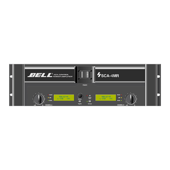
- Seite 4 Bedienelemente Front Netzschalter (Mains) Einschalten der Endstufe zum Normal- und Standby Betrieb. Anzeige über Hintergrund- beleuchtung der Dispays. Level Regler (CH.A / B) Einstellung der Dämpfung des Eingangssignals in ‚dB‘. Der eingestellte Wert wird im Display angezeigt. [View Mode , Page 1] Dämpfung: max 88dB, min. 0.0dB. Remote Active Schalter (mit Led) Aktiviert den Remote Control Modus.
- Seite 5 Ändert im „Command Mode“ den Wert der einzelnen Parameter. Diese Werte können sowohl numerisch als auch Bestätigungen (YES / NO, ON / OFF oder ENABLE / DISABLE) sein. Display mit Hintergrundbeleuchtung CH.A / CH.B Anzeige aller Informationen im Command- und View Mode, sowie eventueller Warnhinweise im Protect Mode.
- Seite 6 Das Umschalten des Impedance Modus des Betriebs während des Betriebs ist zu vermeiden. 2) Nach dem Einschalten der SCA-2MR/4MR wird das System des Amps initialisiert. Hierbei zeigen die Displays folgende Information: 3) Falls im [Command Mode, Page 4] der „Sine Wave Test“ aktiviert wurde, wird dieser jetzt ausgeführt.
- Seite 7 Falls im [Command Mode , Page 5] „Keycode“ aktiviert wurde, zeigen die Displays folgende Information: Der „Standby Mode“ kann nur aufgehoben werden wenn die Ursache des Fehlers be- seitigt wird, oder der korrekte Keycode eingegeben wird, um die Fenster zum Deaktivieren von „Power Control“...
- Seite 8 Dargestellte Parameter SCM Module Zeigt den Typ des eingebauten SCM (Control Moduls) für CH.A und CH.B an. Impedance Mode (SCA4MR) Zeigt den mittels Impedance Mode Schalter gewählten Betriebsmodus (2 Ω/ 4 Ω) an. Level Die mit dem Level Regler, bzw. per Remote Control eingestellte Dämpfung des Ein- gangssignals in „dB“...
- Seite 9 Page 4 Dargestellte Parameter: Output level: Die Endstufenaussteuerung in „dB“ (True RMS) numerisch und als Bargraph für CH.A und CH.B . Die Skalierung des Bargraph beträgt 2dB/Div, d.h. 1dB per dar- gestelltem Bargraphsegment . Vollaussteuerung = 0dB. Page 5 Dargestellte Parameter: Output voltage: Ausgangsspannung in „V“...
- Seite 10 Command Mode Das Aktivieren dieser Funktion erfolgt mit dem „Command“ Schalter (grüne LED an) Eine ausführliche Beschreibung dieser Funktion befindet sich unter: Bedienungselemente auf der Frontwand, „Command“ Schalter. Das Anwählen und Bestätigen des zu ändernden Parameters erfolgt mit der „Enter“ Taste des Wheels.
- Seite 11 Output Power: Ausgangsleistung des Sinusgenerators in Watt für Kanal A. Diese Leistungsangabe bezieht sich bei der SCA-2MR auf 4Ω und bei der SCA-4MR auf 2Ω bzw. 4Ω (je nach gewähltem Impedanz Modus). Die Meßgenauigkeit der Impedanzprüfung steigt mit zunehmender Ausgangsleistung.
- Seite 12 Start: Startfrequenz des digitalen Sinusgenerators. Um Frequenzüberlappungen zu verhindern, ist diese maximal gleich der Stoppfrequenz. Einstellbarer Wertebereich: 50Hz - 10KHz . Stop: Stopfrequenz des digitalen Sinusgenerators. Um Frequenzüberlappungen zu verhindern, ist diese minimal gleich der Startfrequenz. Einstellbarer Wertebereich: 50Hz - 10KHz . Test: Startet die Testprozedur.
- Seite 13 Parameters: Keycode: Aktiviert den vierstelligen Keycode. Nach dessen Eingabe wird der Command Mode nur noch durch Eingabe des Keycode zugänglich.Diese Funktion verhindert unbefugte Änderung von Daten. Der Keycode kann erst aktiviert werden, wenn zuvor mit Hilfe der Funktion „New Keycode“ eine Code eingegeben und gespeichert wurde.Einstellbarer Wertebereich: ENABLE / DISABLE .