Herunterladen Inhalt Inhalt Diese Seite drucken
Inhaltsverzeichnis

Werbung

Verfügbare Sprachen

Verfügbare Sprachen

Quick Start
Thank you for purchasing the MSI
X470 GAMING PLUS
®
motherboard. This Quick Start section provides demonstration
diagrams about how to install your computer. Some of the
installations also provide video demonstrations. Please link to the
URL to watch it with the web browser on your phone or tablet. You
may have even link to the URL by scanning the QR code.
Kurzanleitung
Danke, dass Sie das MSI
X470 GAMING PLUS
Motherboard gewählt
®
haben. Dieser Abschnitt der Kurzanleitung bietet eine Demo zur
Installation Ihres Computers. Manche Installationen bieten auch
die Videodemonstrationen. Klicken Sie auf die URL, um diese
Videoanleitung mit Ihrem Browser auf Ihrem Handy oder Table
anzusehen. Oder scannen Sie auch den QR Code mit Ihrem Handy,
um die URL zu öffnen.
Présentation rapide
Merci d' avoir choisi la carte mère MSI
X470 GAMING
PLUS. Ce
®
manuel fournit une rapide présentation avec des illustrations
explicatives qui vous aideront à assembler votre ordinateur. Des
tutoriels vidéo sont disponibles pour certaines étapes. Cliquez sur
le lien fourni pour regarder la vidéo sur votre téléphone ou votre
tablette. Vous pouvez également accéder au lien en scannant le QR
code qui lui est associé.
Быстрый старт
Благодарим вас за покупку материнской платы MSI
X470
®
PLUS. В этом разделе представлена информация,
GAMING
которая поможет вам при сборке комьютера. Для некоторых
этапов сборки имеются видеоинструкции. Для просмотра
видео, необходимо открыть соответствующую ссылку в
веб-браузере на вашем телефоне или планшете. Вы также
можете выполнить переход по ссылке, путем сканирования
QR-кода.
I
Quick Start

Werbung

Inhaltsverzeichnis
loading

Inhaltszusammenfassung für MSI X470 GAMING PLUS

  • Seite 1 Videoanleitung mit Ihrem Browser auf Ihrem Handy oder Table anzusehen. Oder scannen Sie auch den QR Code mit Ihrem Handy, um die URL zu öffnen. Présentation rapide Merci d’ avoir choisi la carte mère MSI X470 GAMING PLUS. Ce ®...
  • Seite 1 Videoanleitung mit Ihrem Browser auf Ihrem Handy oder Table anzusehen. Oder scannen Sie auch den QR Code mit Ihrem Handy, um die URL zu öffnen. Présentation rapide Merci d’ avoir choisi la carte mère MSI X470 GAMING PLUS. Ce ®...
  • Seite 2 Installing a Processor/ Installation des Prozessors/ Installer un processeur/ Установка процессора https://youtu.be/Xv89nhFk1vc CPU_FAN1 Quick Start...
  • Seite 2 Installing a Processor/ Installation des Prozessors/ Installer un processeur/ Установка процессора https://youtu.be/Xv89nhFk1vc CPU_FAN1 Quick Start...
  • Seite 3 If you are installing the screw-type CPU heatsink, please follow the figure below to remove the retention module first and then install the heatsink. Wenn Sie einen CPU-Kühler mit Schraubenbefestigung einsetzen, folgen Sie bitte den Anweisungen unten um das Retention-Modul zu entfernen und den Kühler zu installieren.
  • Seite 3 If you are installing the screw-type CPU heatsink, please follow the figure below to remove the retention module first and then install the heatsink. Wenn Sie einen CPU-Kühler mit Schraubenbefestigung einsetzen, folgen Sie bitte den Anweisungen unten um das Retention-Modul zu entfernen und den Kühler zu installieren.
  • Seite 4 Installing DDR4 memory/ Installation des DDR4-Speichers/ Installer une mémoire DDR4/ Установка памяти DDR4 http://youtu.be/T03aDrJPyQs DIMMB2 DIMMB2 DIMMB1 DIMMA2 DIMMA2 DIMMA2 DIMMA1 Quick Start...
  • Seite 4 Installing DDR4 memory/ Installation des DDR4-Speichers/ Installer une mémoire DDR4/ Установка памяти DDR4 http://youtu.be/T03aDrJPyQs DIMMB2 DIMMB2 DIMMB1 DIMMA2 DIMMA2 DIMMA2 DIMMA1 Quick Start...
  • Seite 5 Connecting the Front Panel Header/ Anschließen der Frontpanel-Stiftleiste/ Connecter un connecteur du panneau avant/ Подключение разъемов передней панели http://youtu.be/DPELIdVNZUI HDD LED + Power LED + HDD LED - Power LED - Reset Switch Power Switch Reset Switch Power Switch JFP1 Reserved No Pin JFP1...
  • Seite 6 Installing the Motherboard/ Installation des Motherboards/ Installer la carte mère/ Установка материнской платы Quick Start...
  • Seite 7 Installing SATA Drives/ Installation der SATA-Laufwerke/ Installer le disque dur SATA/ Установка дисков SATA http://youtu.be/RZsMpqxythc Quick Start...
  • Seite 8 Installing a Graphics Card/ Einbau der Grafikkarte/ Installer une carte graphique/ Установка дискретной видеокарты http://youtu.be/mG0GZpr9w_A VIII Quick Start...
  • Seite 9 Connecting Peripheral Devices/ Peripheriegeräte/ Connecter un périphérique anschliessen/ Подключение периферийных устройств Quick Start...
  • Seite 10 Connecting the Power Connectors/ Stromanschlüsse anschliessen/ Connecter les câbles du module d’ alimentation/ Подключение разъемов питания http://youtu.be/gkDYyR_83I4 ATX_PWR1 CPU_PWR1 Quick Start...
  • Seite 11: Power On/ Einschalten/ Mettre Sous-Tension/ Включение Питания

    Power On/ Einschalten/ Mettre sous-tension/ Включение питания Quick Start...
  • Seite 12 NOTE Quick Start...
  • Seite 13 Contents Safety Information ....................2 Specifications ......................3 Rear I/O Panel ....................... 8 LAN Port LED Status Table..................8 Audio Ports Configuration ..................8 Realtek HD Audio Manager ..................9 Overview of Components ..................11 CPU Socket ......................12 DIMM Slots ......................13 PCI_E1~6: PCIe Expansion Slots ................
  • Seite 14: Safety Information

    Safety Information y The components included in this package are prone to damage from electrostatic discharge (ESD). Please adhere to the following instructions to ensure successful computer assembly. y Ensure that all components are securely connected. Loose connections may cause the computer to not recognize a component or fail to start.
  • Seite 15 Supports ECC UDIMM memory * A-series/ Athlon™ processors support up to 2400 MHz. And the supporting frequency of memory varies with installed processor. Please refer www.msi.com for more information on compatible memory. y 2x PCIe 3.0 x16 slots (PCIE_1, PCIE_4) ƒ...
  • Seite 16 Continued from previous page y 6x SATA 6Gb/s ports (from AMD X470 Chipset) ® y 2x M.2 ports (Key M)* ƒ M2_1 slot (from AMD processor) supports PCIe 3.0 x4 ® (Ryzen™ Desktop Processors ) or PCIe 3.0 x2 (A-series/ Athlon™...
  • Seite 17 Continued from previous page y 1x PS/2 keyboard/ mouse combo port y 2x USB 2.0 Type-A ports y 1x DVI-D port y 1x HDMI™ 1.4 port Back Panel y 4x USB 3.1 Gen1 Type-A ports Connectors y 1x LAN (RJ45) port y 2x USB 3.1 Gen2 Type-A ports y 5x OFC audio jacks y 1x Optical S/PDIF OUT connector...
  • Seite 18 GAMING APP Software y RAMDISK y X-BOOST y SMART TOOL y Nahimic Audio y Open Broadcaster Software (OBS) y Norton™ Internet Security Solution y Google Chrome™, Google Toolbar, Google Drive y CPU-Z MSI GAMING Continued on next page Specifications...
  • Seite 19 Continued from previous page y Audio ƒ Audio Boost ƒ Voice Boost ƒ Nahimic 2.5 y Storage ƒ Turbo M.2 y Fan ƒ Pump Fan ƒ Smart Fan Control y LED ƒ Mystic Light ƒ Mystic Light Extension ƒ Mystic light SYNC ƒ...
  • Seite 20: Rear I/O Panel

    Rear I/O Panel Audio Ports USB 3.1 Gen1 PS/2 DVI-D USB 2.0 USB 3.1 Gen2 Optical S/PDIF-Out USB 3.1 Gen1 LAN Port LED Status Table Link/ Activity LED Speed LED Status Description Status Description No link 10 Mbps connection Yellow Linked Green 100 Mbps connection...
  • Seite 21: Realtek Hd Audio Manager

    Realtek HD Audio Manager After installing the Realtek HD Audio driver, the Realtek HD Audio Manager icon will appear in the system tray. Double click on the icon to launch. Device Selection Advanced Settings Jack Status Application Enhancement Main Volume Connector Settings Profiles...
  • Seite 22 Audio jacks to headphone and microphone diagram Audio jacks to stereo speakers diagram AUDIO INPUT Audio jacks to 7.1-channel speakers diagram AUDIO INPUT Rear Front Side Center/ Subwoofer Rear I/O Panel...
  • Seite 23: Overview Of Components

    Overview of Components DIMMB1 DIMMA2 DIMMB2 DIMMA1 SYS_FAN1 CPU_PWR2 CPU_FAN1 CPU_PWR1 CPU Socket PUMP_FAN1 SYS_FAN3 ATX_PWR1 JRGB2 SYS_FAN4 M2_1 PCI_E1 JUSB4 PCI_E2 JTPM1 PCI_E3 SATA▼5▲6 JCI1 PCI_E4 SATA▼3▲4 JBAT1 PCI_E5 SATA▼1▲2 M2_2 PCI_E6 JFP2 JAUD1 JCOM1 JRGB1 JLPT1 JFP1 SYS_FAN2 JUSB3 Clear CMOS JUSB2...
  • Seite 24: Cpu Socket

    This motherboard is designed to support overclocking. Before attempting to overclock, please make sure that all other system components can tolerate overclocking. Any attempt to operate beyond product specifications is not recommended. MSI does not guarantee the damages or risks caused by inadequate ®...
  • Seite 25: Dimm Slots

    Due to AM4 CPU/memory controller official specification limitation, the frequency of memory modules may operate lower than the marked value under the default state. Please refer www.msi.com for more information on compatible memory. Overview of Components...
  • Seite 26: Pci_E1~6: Pcie Expansion Slots

    Important If you install a large and heavy graphics card, you need to use a tool such as MSI Gaming Series Graphics Card Bolster to support its weight to prevent deformation of the slot. For a single PCIe x16 expansion card installation with optimum performance, using the PCI_E1 slot is recommended.
  • Seite 27 PCIe bandwidth table For Ryzen™ Desktop processors Slot Single 2-Way PCI_E1 (CPU) Gen 3.0 x 16* Gen 3.0 x 8* PCI_E2 (PCH) Gen 2.0 x 1 Gen 2.0 x 1 PCI_E3 (PCH) Gen 2.0 x 1 Gen 2.0 x 1 ─...
  • Seite 28: M2_1~2: M.2 Slots (Key M)

    M2_1~2: M.2 Slots (Key M) Important SATA1 port will be unavailable when installing SATA M.2 SSD in M2_2 slot. PCI_E6 slot will be unavailable when installing PCIe M.2 SSD in M2_2 slot. M2_1 M2_1 slot only supports PCIe mode. M2_2 Video Demonstration Watch the video to learn how to Install M.2 SSD.
  • Seite 29: Sata1~6: Sata 6Gb/S Connectors

    SATA1~6: SATA 6Gb/s Connectors These connectors are SATA 6Gb/s interface ports. Each connector can connect to one SATA device. SATA6 SATA5 SATA4 SATA3 SATA2 SATA1 Important SATA1 port will be unavailable when installing SATA M.2 SSD in M2_2 slot. Please do not fold the SATA cable at a 90-degree angle. Data loss may result during transmission otherwise.
  • Seite 30 CPU_PWR1, CPU_PWR2, ATX_PWR1: Power Connectors These connectors allow you to connect an ATX power supply. CPU_PWR1 Ground +12V Ground +12V Ground +12V Ground +12V CPU_PWR2 Ground +12V Ground +12V +3.3V +3.3V +3.3V -12V Ground Ground PS-ON# Ground Ground Ground ATX_PWR1 Ground Ground PWR OK...
  • Seite 31: Jusb1~2: Usb 2.0 Connectors

    JUSB1~2: USB 2.0 Connectors These connectors allow you to connect USB 2.0 ports on the front panel. USB0- USB1- USB0+ USB1+ Ground Ground No Pin Important Note that the VCC and Ground pins must be connected correctly to avoid possible damage.
  • Seite 32: Cpu_Fan1, Pump_Fan1, Sys_Fan1~4: Fan Connectors

    CPU_FAN1, PUMP_FAN1, SYS_FAN1~4: Fan Connectors Fan connectors can be classified as PWM (Pulse Width Modulation) Mode or DC Mode. PWM Mode fan connectors provide constant 12V output and adjust fan speed with speed control signal. DC Mode fan connectors control fan speed by changing voltage.
  • Seite 33: Jaud1: Front Audio Connector

    JAUD1: Front Audio Connector This connector allows you to connect audio jacks on the front panel. MIC L Ground MIC R Head Phone R MIC Detection SENSE_SEND No Pin Head Phone L Head Phone Detection JCI1: Chassis Intrusion Connector This connector allows you to connect the chassis intrusion switch cable. Normal Trigger the chassis intrusion event...
  • Seite 34: Jfp1, Jfp2: Front Panel Connectors

    JFP1, JFP2: Front Panel Connectors These connectors connect to the switches and LEDs on the front panel. JFP1 HDD LED + Power LED + HDD LED - Power LED - Reset Switch Power Switch Reset Switch Power Switch Reserved No Pin Speaker - Buzzer + JFP2...
  • Seite 35: Jcom1: Serial Port Connector

    Please keeping the LED strip shorter than 2 meters to prevent dimming. Always turn off the power supply and unplug the power cord from the power outlet before installing or removing the RGB LED strip. Please use MSI’ s software to control the extended LED strip. Overview of Components...
  • Seite 36: Jbat1: Clear Cmos (Reset Bios) Jumper

    JBAT1: Clear CMOS (Reset BIOS) Jumper There is CMOS memory onboard that is external powered from a battery located on the motherboard to save system configuration data. If you want to clear the system configuration, set the jumpers to clear the CMOS memory. Keep Data Clear CMOS/ Reset BIOS...
  • Seite 37: Entering Bios Setup

    BIOS Setup The default settings offer the optimal performance for system stability in normal conditions. You should always keep the default settings to avoid possible system damage or failure booting unless you are familiar with BIOS. Important BIOS items are continuously update for better system performance. Therefore, the description may be slightly different from the latest BIOS and should be for reference only.
  • Seite 38: Resetting Bios

    Updating BIOS Updating BIOS with M-FLASH Before updating: Please download the latest BIOS file that matches your motherboard model from MSI website. And then save the BIOS file into the USB flash drive. Updating BIOS: 1. Insert the USB flash drive that contains the update file into the computer.
  • Seite 39 EZ Mode At EZ mode, it provides the basic system information and allows you to configure the basic setting. To configure the advanced BIOS settings, please enter the Advanced Mode by pressing the Setup Mode switch or F7 function key. A-XMP switch Setup Mode switch Screenshot...
  • Seite 40 Review by clicking on their respective button. Important During windows setup, the RAID driver may be required and you can find the RAID driver in MSI Driver Disc. You can use MSI SMART TOOL to build the Windows installation drive that includes ® RAID driver.
  • Seite 41: Advanced Mode

    Advanced Mode Press Setup Mode switch or F7 function key can switch between EZ Mode and Advanced Mode in BIOS setup. A-XMP switch Setup Mode switch Screenshot Search Language System information GAME BOOST switch Boot device priority bar BIOS menu BIOS menu selection selection...
  • Seite 42 OC Menu This menu is for advanced users who want to overclock the motherboard. Important Overclocking your PC manually is only recommended for advanced users. Overclocking is not guaranteed, and if done improperly, it could void your warranty or severely damage your hardware. If you are unfamiliar with overclocking, we advise you to use GAME BOOST function for easy overclocking.
  • Seite 43 f Memory Try It ! [Disabled] It can improve memory compatibility or performance by choosing optimized memory preset. f Memory Retry Count [5] Sets counts for memory OC retrying. When memory OC has failed, setting this item as [5] will allow system to reboot 5 times with the same overclocked configuration. If overclocking has failed every time, the system will restore the defaults.
  • Seite 44 fCPU Power Duty Control [Thermal Balance] Sets the current of every VRM phase and the thermal conditions of every phase component. [Thermal Balance] Maintains the VRM thermal balance. [Current Balance] Maintains the current VRM balance. fCPU NB Loadline Calibration Control [Auto] The CPU-NB voltage will decrease proportionally according to CPU-NB loading.
  • Seite 45 Press Enter to enter the sub-menu. This sub-menu displays the information of installed CPU. You can also access this information menu at any time by pressing [F4]. Read only. fCPU Technology Support Press Enter to enter the sub-menu. The sub-menu shows the key features of installed CPU.
  • Seite 46 fRelaxed EDC throttling [Auto] (optional) Relaxed EDC throttling reduces the amount of time the processor will throttle the cores. [Auto] AMD's recommendation [Enabled] Reduce the amount of time the processor will throttle. [Disabled] Part-specific EDC throttling protection enabled. fAMD Cool’ n’ Quiet [Enabled] The Cool’...
  • Seite 47: Software Description

    7. Follow the instructions on the screen to install Windows ® Installing Drivers 1. Start up your computer in Windows ® 2. Insert MSI Driver Disc into your optical drive. ® 3. The installer will automatically appear and it will find and list all necessary drivers.
  • Seite 48 NOTE Software Description...
  • Seite 49 Inhalt Sicherheitshinweis ....................2 Spezifikationen ...................... 3 Rückseite E/A ......................8 LAN Port LED Zustandstabelle ................8 Konfiguration der Audioanschlüsse ............... 8 Realtek HD Audio Manager ..................9 Übersicht der Komponenten ................11 CPU Sockel ......................12 DIMM Steckplätze ....................13 PCI_E1~6: PCIe Erweiterungssteckplätze ............
  • Seite 50: Sicherheitshinweis

    Sicherheitshinweis y Die im Paket enthaltene Komponenten sind der Beschädigung durch elektrostatischen Entladung (ESD). Beachten Sie bitte die folgenden Hinweise, um die erfolgreichen Computermontage sicherzustellen. y Stellen Sie sicher, dass alle Komponenten fest angeschlossen sind. Lockere Steckverbindungen können Probleme verursachen, zum Beispiel: Der Computer erkennt eine Komponente nicht oder startet nicht.
  • Seite 51: Spezifikationen

    Prozessoren unterstützen bis zu 2400 MHz. Die ™ unterstützende Frequenz des Speichers ist unterschiedlich je nach dem installierten Prozessor. Weitere Informationen zu kompatiblen Speicher finden Sie unter: http://www.msi.com. y 2x PCIe 3.0 x16-Steckplätze (PCIE_1, PCIE_4) ƒ Ryzen Desktop-Prozessoren unterstützen x16/x0, x8/ ™...
  • Seite 52: Aufbewahrung

    Fortsetzung der vorherigen Seite y 6x SATA 6Gb/s ports (aus dem AMD X470 Chipsatz) ® y 2x M.2 Anschlüsse (Key M)* ƒ M2_1 Steckplatz (aus dem AMD Prozessor) unterstützt ® PCIe 3.0 x4 (Ryzen Desktop-Prozessoren ) oder PCIe ™ 3.0 x2 (A-Serie/ Athlon Prozessoren) 2242/ 2260 /2280/ ™...
  • Seite 53: Anschluss

    Fortsetzung der vorherigen Seite y 1x PS/2 Tastatur/ Maus-Combo-Anschluss y 2x USB 2.0 Typ-A Anschlüsse y 1x DVI-D Anschluss y 1x HDMI 1.4 Anschluss ™ Hintere Ein-/ und y 4x USB 3.1 Gen1 Typ-A Anschlüsse Ausgänge y 1x LAN (RJ45) Anschluss y 2x USB 3.1 Gen2 Typ-A Anschlüsse y 5x OFC Audiobuchsen y 1x Optischer S/PDIF-Ausgang...
  • Seite 54 RAMDISK y X-BOOST y SMART TOOL y Nahimic Audio y Open Broadcaster Software (OBS) y Norton Internet Security Solution ™ y Google Chrome , Google Toolbar, Google Drive ™ y CPU-Z MSI GAMING Fortsetzung auf der nächsten Seite Spezifikationen...
  • Seite 55: Besondere Funktionen

    Fortsetzung der vorherigen Seite y Audio ƒ Audio Boost ƒ Voice Boost ƒ Nahimic 2.5 y Speicherung ƒ Turbo M.2 y Lüfter ƒ Pump-Lüfter ƒ Smart-Lüftersteuerung y LED ƒ Mystic Light ƒ Mystic Light Extension ƒ Mystic Light SYNC ƒ EZ DEBUG LED y Schutz ƒ...
  • Seite 56: Lan Port Led Zustandstabelle

    Rückseite E/A Audioanschlüsse USB 3.1 Gen1 PS/2 DVI-D USB 2.0 USB 3.1 Gen2 Optischer S/PDIF USB 3.1 Gen1 Ausgang LAN Port LED Zustandstabelle Verbindung/ Aktivität LED Geschwindigkeit LED Zustand Bezeichnung Zustand Bezeichnung Keine Verbindung 10 Mbps-Verbindung Gelb Verbindung Grün 100 Mbps-Verbindung Blinkt Datenaktivität Orange...
  • Seite 57: Realtek Hd Audio Manager

    Realtek HD Audio Manager Nach der Installation des Realtek HD Audio-Treibers, wird das Symbol Realtek HD Audio Manager in der Taskleiste angezeigt. Klicken Sie doppelt auf dieses Symbol, um das Programm zu starten. Geräteauswahl Erweiterte Einstellungen Verbindungs- status Optimierungen Lautstärke Anschlüsse Profil y Geräteauswahl - Ermöglicht die Auswahl der Audio-Ausgangs Quelle.
  • Seite 58: Audiobuchsen Für Stereo-Lautsprecher

    Audiobuchsen für den Anschluss von einem Kopfhörer und Mikrofon Audiobuchsen für Stereo-Lautsprecher AUDIO INPUT Audiobuchsen für 7.1 Kanal Anlage AUDIO INPUT Rear Front Side Center/ Subwoofer Rückseite E/A...
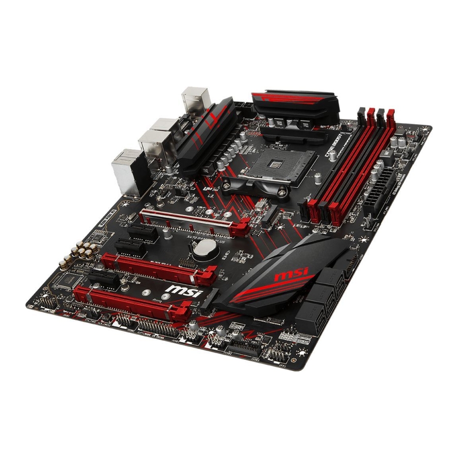
  • Seite 59: Übersicht Der Komponenten

    Übersicht der Komponenten DIMMB1 DIMMA2 DIMMB2 DIMMA1 SYS_FAN1 CPU_PWR2 CPU_FAN1 CPU_PWR1 CPU Sockel PUMP_FAN1 SYS_FAN3 ATX_PWR1 JRGB2 SYS_FAN4 M2_1 PCI_E1 JUSB4 PCI_E2 JTPM1 PCI_E3 SATA▼5▲6 JCI1 PCI_E4 SATA▼3▲4 JBAT1 PCI_E5 SATA▼1▲2 M2_2 PCI_E6 JFP2 JAUD1 JCOM1 JRGB1 JLPT1 JFP1 SYS_FAN2 JUSB3 Clear CMOS JUSB2...
  • Seite 60: Cpu Sockel

    Sie jedoch bitte sicher, dass die betroffenen Komponenten mit den abweichenden Einstellungen während des Übertaktens zurecht kommen. Von jedem Versuch des Betriebes außerhalb der Produktspezifikationen kann nur abgeraten werden. MSI übernehmt keinerlei Garantie für die Schäden und Risiken, die aus einem unzulässigem Betrieb oder einem Betrieb außerhalb der Produktspezifikation resultieren.
  • Seite 61: Dimm-Steckplätze

    CPU und den installierten Geräten. Speichermodule können auf Basis der offizielle Spezifikation der AM4 CPU/ Speicher-Controller mit einer niedrigeren Frequenz unter dem Standardzustand arbeiten. Weitere Informationen zu kompatiblen Speichermodulen finden Sie unter: http://www.msi.com. Übersicht der Komponenten...
  • Seite 62: Pci_E1~6: Pcie Erweiterungssteckplätze

    PCI_E1~6: PCIe Erweiterungssteckplätze PCI_E1: PCIe 3.0 x16*/ PCIe 3.0 x8** PCI_E2: PCIe 2.0 x1 PCI_E3: PCIe 2.0 x1 PCI_E4: PCIe 3.0 x8*/ nicht verfügbar** PCI_E5: PCIe 2.0 x1 PCI_E6: PCIe 2.0 x4 * Für Ryzen Desktop-Prozessoren ™ ** Für Ryzen Desktop-Prozessoren mit Radeon Vega Grafikkarte &...
  • Seite 63 Tabelle der PCIe Bandbreiten Für Ryzen Desktop-Prozessoren ™ Steckplatz Einzel 2-Wege PCI_E1 (CPU) Gen 3.0 x 16* Gen 3.0 x 8* PCI_E2 (PCH) Gen 2.0 x 1 Gen 2.0 x 1 PCI_E3 (PCH) Gen 2.0 x 1 Gen 2.0 x 1 ─...
  • Seite 64: M2_1~2: M.2 Steckplätze (Key M)

    M2_1~2: M.2 Steckplätze (Key M) Wichtig Der SATA1 Steckplatz wird nicht zur Verfügung, wenn Sie eine SATA M.2 SSD in M2_2 slot. Der PCI_E6 Steckplatz wird nicht zur Verfügung, wenn Sie eine PCIe M.2 SSD in M2_2 slot. M2_1 Der M2_1 Steckplatz unterstützt nur den PCIe Modus. M2_2 Video-Demonstration In diesem Video erfahren Sie, wie Sie die M.2 SSD installieren.
  • Seite 65: Sata1~6: Sata 6Gb/S Anschlüsse

    SATA1~6: SATA 6Gb/s Anschlüsse Dieser Anschluss basiert auf der Hochgeschwindigkeitsschnittstelle SATA 6 Gb/s. Pro Anschluss kann ein SATA Gerät angeschlossen werden. SATA6 SATA5 SATA4 SATA3 SATA2 SATA1 Wichtig Der SATA1 Steckplatz wird nicht zur Verfügung, wenn Sie eine SATA M.2 SSD im M2_2 -Steckplatz installieren.
  • Seite 66 CPU_PWR1, CPU_PWR2, ATX_PWR1: Stromanschlüsse Mit diesen Anschlüssen verbinden Sie die ATX Stromstecker. CPU_PWR1 Ground +12V Ground +12V Ground +12V Ground +12V CPU_PWR2 Ground +12V Ground +12V +3.3V +3.3V +3.3V -12V Ground Ground PS-ON# Ground Ground Ground ATX_PWR1 Ground Ground PWR OK 5VSB +12V +12V...
  • Seite 67: Jusb1~2: Usb 2.0 Anschlüsse

    Bitte beachten Sie, dass Sie die mit VCC (Stromführende Leitung) und Ground (Erdleitung) bezeichneten Pins korrekt verbinden müssen, ansonsten kann es zu Schäden kommen. Um ein iPad, iPhone und einen iPod über USB-Anschlüsse aufzuladen, installieren Sie bitte die MSI SUPER CHARGER Software. ® JUSB3~4: USB 3.1 Gen1 Anschlüsse Mit diesen Anschlüssen können Sie die USB 3.1 Gen1 Anschlüsse auf dem Frontpanel...
  • Seite 68 CPU_FAN1, PUMP_FAN1, SYS_FAN1~4: Stromanschlüsse für Lüfter Diese Anschlüsse können im PWM (Pulse Width Modulation) Modus oder Spannungsmodus betrieben werden. Im PWM-Modus bieten die Lüfteranschlüsse konstante 12V Ausgang und regeln die Lüftergeschwindigkeit per Drehzahlsteuersignal. Im DC-Modus bestimmen die Lüfteranschlüsse die Lüftergeschwindigkeit durch Ändern der Spannung. Wenn Sie ein 3-Pin (Non-PWM) Lüfter an einen PWM-Modus Lüfteranschluss anschließen, läuft der Lüfter mit höchster Drehzahl und kann unangenehm laut werden.
  • Seite 69: Jaud1: Audioanschluss Des Frontpanels

    JAUD1: Audioanschluss des Frontpanels Dieser Anschluss ermöglicht den Anschluss von Audiobuchsen eines Frontpanels. MIC L Ground MIC R Head Phone R MIC Detection SENSE_SEND No Pin Head Phone L Head Phone Detection JCI1: Gehäusekontaktanschluss Dieser Anschluss wird mit einem Kontaktschalter verbunden. Normal Löse den Gehäuseeingriff aus...
  • Seite 70: Jfp1, Jfp2: Frontpanel-Anschlüsse

    JFP1, JFP2: Frontpanel-Anschlüsse Diese Anschlüsse verbinden die Schalter und LEDs des Frontpanels. JFP1 HDD LED + Power LED + HDD LED - Power LED - Reset Switch Power Switch Reset Switch Power Switch Reserved No Pin Speaker - Buzzer + JFP2 Buzzer - Speaker +...
  • Seite 71: Jcom1: Serieller Anschluss

    Beachten Sie bitte, dass die Länge des LED-Streifens maximal 2 Meter betragen darf um eine Verdunkelung der LED zu verhindern. Schalten Sie die Stromversorgung aus und ziehen Sie das Netzkabel ab, bevor Sie die RGB-LED-Streifen ein- und ausbauen. Bitte verwenden Sie die MSI-Software zur Steuerung des LED-Leuchtstreifens. Übersicht der Komponenten...
  • Seite 72: Jbat1: Clear Cmos Steckbrücke (Reset Bios)

    JBAT1: Clear CMOS Steckbrücke (Reset BIOS) Der Onboard CMOS Speicher (RAM) wird durch eine externe Spannungsversorgung durch eine Batterie auf dem Motherboard versorgt, um die Daten der Systemkonfiguration zu speichern. Wenn Sie die Systemkonfiguration löschen wollen, müssen Sie die Steckbrücke für kurze Zeit umsetzen. Daten CMOS-Daten beibehalten...
  • Seite 73: Öffnen Des Bios Setups

    BIOS Setup Die Standardeinstellungen bieten die optimale Leistung für die Systemstabilität unter Normalbedingungen. Sie sollten immer die Standardeinstellungen behalten, um mögliche Schäden des Systems oder Boot-Fehler zu vermeiden, außer Sie besitzen ausreichende BIOS Kenntnisse. Wichtig BIOS Funktionen werden für eine bessere Systemleistung kontinuierlich aktualisiert. Deswegen können die Beschreibungen leicht von der letzten Fassung des BIOS abweichen und sollten demnach nur als Anhaltspunkte dienen.
  • Seite 74: Reset Des Bios

    Aktualisierung des BIOS mit dem M-FLASH-Programm Vorbereitung: Laden Sie bitte die neueste BIOS Version, die dem Motherboard-Modell entspricht, von der offiziellen MSI Website herunter und speichern Sie die BIOS-Datei auf USB-Flash- Laufwerk. BIOS-Aktualisierungsschritte: 1. Schließen das USB-Flashlaufwerk mit der BIOS-Datei an den Computer.
  • Seite 75 EZ Modus Im EZ-Modus können Sie die Grundinformationen des Systems einsehen und grundlegende Einstellungen konfigurieren. Um sich die erweiterten BIOS- Einstellungen anzeigen zu lassen, aktivieren Sie bitte den Erweiterten Modus durch Drücken des Setup Modus Schalter oder der Funktionstaste F7. A-XMP Schalter Setup Modus Schalter Screenshot...
  • Seite 76 BIOS Log Review durch Anklicken der zugehörigen Schaltfläche. Wichtig Während des Windows Setup-Vorgangs benötigen Sie den RAID-Treiber, den Sie auf der MSI-Treiber-CD finden. Sie können das MSI SMART TOOL verwenden, um das Windows 7/ 8.1/ 10- ® Installationslaufwerk mit dem RAID-Treiber zu erstellen.
  • Seite 77: Erweiterter Modus

    Erweiterter Modus Drücken Sie den Setup Modus Schalter oder die Funkionstaste F7, um zwischen dem EZ-Modus und Erweiterten-Modus im BIOS-Setup zu wechseln. A-XMP Schalter Setup Modus Schalter Screenshot Suchen Sprache System- information GAME BOOST Schalter Bootgeräte- Prioritätsleiste BIOS-Menü BIOS-Menü -Auswahl -Auswahl Menüanzeige y GAME BOOST Schalter/ Setup Modus Schalter/ Screenshot/ Sprache/...
  • Seite 78 OC Menü In diesem Menü können Benutzer das BIOS anpassen und das Mainboard übertakten. Bitte führen Sie nur Änderungen durch, wenn Sie sich über das Ergebnis im Klaren sind. Sie sollten Erfahrung beim Übertakten haben, da Sie sonst das Motherboard oder Komponenten des Systems beschädigen können.
  • Seite 79 f A-XMP [Disabled] Aktivieren Sie die A-XMP Funktion oder wählen Sie ein Profil des Speichermoduls aus, um den Speicher zu übertakten. Diese Option erscheint nur, wenn die installierten Speichermodule/ das installierte Motherboard diese Funktion unterstützen. f DRAM Frequency [Auto] Setzen Sie die DRAM Frequenz. Bitte beachten Sie, dass ein zuverlässiges Übertaktungsverhalten nicht garantiert werden kann.
  • Seite 80 fCPU Over Current Protection [Auto] Legen Sie den aktuellen Grenzwert für den CPU-Überstromschutz fest. Wenn die Einstellung auf Auto gesetzt ist, wird das BIOS diese Einstellungen automatisch konfigurieren. [Auto] Diese Einstellungen werden vom BIOS automatisch konfiguriert. [Enhanced] Erweitert die Begrenzung des Speicher-Überstromschutz. fCPU Switching Frequency [Auto] Stellen Sie die PWM Arbeitsgeschwindigkeit ein, um die CPU Core-Spannung und den Ripple Bereich zu stabilisieren.
  • Seite 81 fVR 12VIN OCP Expander [Auto] Erweitert die Begrenzung des VR-Überstromschutzes mit 12 V Eingangsspannung. Dies kann aufgrund erhöhter Toleranz einen geringeren Schutz bedeuten. Bitte passen Sie deshalb den Strom sorgfältig an, um Beschädigungen des CPU/ VR MOS zu vermeiden. Wenn die Einstellung auf [Auto] gesetzt ist, wird das BIOS diese Einstellungen automatisch konfigurieren.
  • Seite 82 fOpcache Control [Auto] (optional) Aktiviert oder deaktiviert die Opcache-Funkiton. Opcache speichert die letzte dekodierte Anweisung um die Dekodierzeit bei wiederholten Anweisungen zu verringern. Zusätzlich kann es die CPU-Leistung erhöhen und den Stromverbrauch leicht reduzieren. fIOMMU Mode (optional) Hier können Sie den IOMMU (I/O Memory Management Unit) für I/O-Virtualisierung aktivieren/ deaktivieren.
  • Seite 83: Softwarebeschreibung

    ® Installation von Treibern 1. Starten Sie Ihren Computer mit Windows ® 2. Legen Sie die MSI Treiber Disk in das optisches Laufwerk. ® 3. Der Installer wird automatisch erscheint und findet und finden Sie die benötigten Treiber in die Liste.
  • Seite 84: Anmerkung

    Anmerkung Softwarebeschreibung...
  • Seite 85 Table des matières Informations de sécurité ..................2 Spécifications ......................3 Panneau arrière Entrée/ Sortie ................8 Tableau explicatif de l’ état de la LED du port LAN ..........8 Configuration des ports audio ................8 Realtek HD Audio Manager ..................9 Vue d’...
  • Seite 86: Informations De Sécurité

    Informations de sécurité y Les composants dans l’ emballage peuvent être endommagés par des décharges électrostatiques (ESD). Pour vous assurer de correctement monter votre ordinateur, veuillez vous référer aux instructions ci-dessous. y Assurez-vous de bien connecter tous les composants. En cas de mauvaise connexion, il se peut que l’...
  • Seite 87 * Les processeurs de série A ou Athlon™ supportent jusqu’ à 2400 MHz. La fréquence mémoire supportée varie selon le processeur installé. Veuillez vous référer au site www.msi.com pour plus d’ informations sur la mémoire compatible. y 2 x slots PCIe 3.0 x16 (PCI_E1, PCI_E4) ƒ...
  • Seite 88 Suite du tableau de la page précédente 1 x contrôleur Realtek 8111H Gigabit LAN ® y 6 x ports SATA 6 Gb/s (du chipset AMD X470) ® y 2 x ports M.2 (Touche M)* ƒ Le slot M2_1 (du processeur AMD ) supporte PCIe ®...
  • Seite 89: Connecteurs Internes

    Suite du tableau de la page précédente y 1 x port clavier/ souris PS/2 y 2 x ports USB 2.0 Type-A y 1 x port DVI-D y 1 x port HDMI™ 1.4 Connecteurs sur le y 4 x ports USB 3.1 Gen1 Type-A panneau arrière y 1 x port LAN (RJ45) y 2 x ports USB 3.1 Gen2 Type-A...
  • Seite 90 RAMDISK y X-BOOST y SMART TOOL y Nahimic Audio y Open Broadcaster Software (OBS) y Norton™ Internet Security Solution y Google Chrome™, Google Toolbar et Google Drive y CPU-Z MSI GAMING Suite du tableau sur la page suivante Spécifications...
  • Seite 91 Suite du tableau de la page précédente y Audio ƒ Audio Boost ƒ Voice Boost ƒ Nahimic 2.5 y Stockage ƒ Turbo M.2 y Ventilateur ƒ Ventilateurs pour la pompe ƒ Contrôle des ventilateurs y LED ƒ Mystic Light ƒ Mystic Light Extension ƒ...
  • Seite 92: Panneau Arrière Entrée/ Sortie

    Panneau arrière Entrée/ Sortie Ports audio USB 3.1 Gen1 PS/2 DVI-D USB 2.0 USB 3.1 Gen2 Sortie S/PDIF optique USB 3.1 Gen1 Tableau explicatif de l’ état de la LED du port LAN LED indiquant la connexion LED indiquant la vitesse et l’...
  • Seite 93 Realtek HD Audio Manager Après l’ installation du pilote Realtek HD Audio, l’ icône Realtek HD Audio Manager apparaît dans la barre des tâches du système. Double-cliquez sur l’ icône pour lancer le programme. Sélection du périphérique Paramètres avancés Etat des prises Jack Amélioration d’...
  • Seite 94 Ilustration de l’ utilisation des ports audio dédiés au casque et au microphone Ilustration de l’ utilisation du port audio dédié aux haut-parleurs AUDIO INPUT Ilustration de l’ utilisation des ports audio dédiés aux haut-parleurs 7.1 AUDIO INPUT Rear Front Side Center/ Subwoofer...
  • Seite 95: Vue D' Ensemble Des Composants

    Vue d’ ensemble des composants DIMMB1 DIMMA2 DIMMB2 DIMMA1 SYS_FAN1 CPU_PWR2 CPU_FAN1 Socket CPU_PWR1 processeur PUMP_FAN1 SYS_FAN3 ATX_PWR1 JRGB2 SYS_FAN4 M2_1 PCI_E1 JUSB4 PCI_E2 JTPM1 PCI_E3 SATA▼5▲6 JCI1 PCI_E4 SATA▼3▲4 JBAT1 PCI_E5 SATA▼1▲2 M2_2 PCI_E6 JFP2 JAUD1 JCOM1 JRGB1 JLPT1 JFP1 SYS_FAN2 JUSB3...
  • Seite 96: Socket Processeur

    Cette carte mère supporte l’ overclocking. Néanmoins, veuillez vous assurer que vos composants soient capables de tolérer l’ overclocking. Prenez note que l’ utilisation au-delà des spécifications du constructeur n’ est pas recommandée. MSI ne garantit ®...
  • Seite 97: Slots Dimm

    Du fait des limites officiels des spécifications du contrôleur CPU/ mémoire AM4, les modules de mémoire peuvent fonctionner à une fréquence réduite par rapport à la valeur indiquée en mode défaut. Veuillez vous référer au site www.msi.com pour plus d’ informations sur la mémoire compatible.
  • Seite 98: Pci_E1~6 : Slots D' Extension Pcie

    Ryzen™) Important Si vous installez une carte graphique lourde, il vous faut utiliser un outil comme la barre de support MSI Gaming Series pour supporter son poids et pour éviter la déformation du slot. Si vous choisissez d’ installer une seule carte d’...
  • Seite 99 Tableaux de débit PCIe Pour les processeurs de bureau Ryzen™ Slot Unique 2-Way PCI_E1 (CPU) Gen 3.0 x 16* Gen 3.0 x 8* PCI_E2 (PCH) Gen 2.0 x 1 Gen 2.0 x 1 PCI_E3 (PCH) Gen 2.0 x 1 Gen 2.0 x 1 ─...
  • Seite 100: M2_1~2 : Slots M.2 (Touche M)

    M2_1~2 : Slots M.2 (Touche M) Important Le port SATA1 est indisponible lorsqu’ un SSD SATA M.2 est installé dans le slot M2_2. Le slot PCI_E6 est indisponible lorsqu’ un SSD PCIe M.2 est installé dans le slot M2_2. M2_1 Le slot M2_1 supporte seulement le mode PCIe.
  • Seite 101: Sata1~6 : Connecteurs Sata 6 Gb/S

    SATA1~6 : Connecteurs SATA 6 Gb/s Ces connecteurs utilisent une interface SATA 6 Gb/s. Chaque connecteur peut être relié à un appareil SATA. SATA6 SATA5 SATA4 SATA3 SATA2 SATA1 Important Le port SATA1 est indisponible lorsqu’ un SSD SATA M.2 est installé dans le slot M2_2.
  • Seite 102 CPU_PWR1, CPU_PWR2, ATX_PWR1 : Connecteurs d’ alimentation Ces connecteurs vous permettent de relier une alimentation ATX. CPU_PWR1 Ground +12V Ground +12V Ground +12V Ground +12V CPU_PWR2 Ground +12V Ground +12V +3.3V +3.3V +3.3V -12V Ground Ground PS-ON# Ground Ground Ground ATX_PWR1 Ground Ground...
  • Seite 103: Jusb3~4 : Connecteurs Usb 3.1 Gen1

    Notez que les broches VCC et Terre doivent être branchées correctement afin d’ éviter tout dommage sur la carte mère. Pour recharger votre iPad, iPhone et iPod par l’ intermédiaire d’ un port USB, veuillez installer l’ utilitaire MSI SUPER CHARGER. ®...
  • Seite 104 CPU_FAN1, PUMP_FAN1, SYS_FAN1~4 : Connecteurs pour ventilateurs Les connecteurs pour ventilateurs peuvent être utilisés en mode PWM (Pulse Width Modulation) et en mode DC. En mode PWM, les connecteurs fournissent une sortie de 12V constante et ajustent la vitesse des ventilateurs avec un signal de contrôle de vitesse.
  • Seite 105: Jaud1 : Connecteur Audio Avant

    JAUD1 : Connecteur audio avant Ce connecteur se lie aux jacks audio du panneau avant. MIC L Ground MIC R Head Phone R MIC Detection SENSE_SEND No Pin Head Phone L Head Phone Detection JCI1 : Connecteur intrusion châssis Ce connecteur est relié à un câble d’ interrupteur intrusion châssis. Normal Commencer l’...
  • Seite 106: Jfp1, Jfp2 : Connecteurs De Panneau Avant

    JFP1, JFP2 : Connecteurs de panneau avant Ces connecteurs se lient aux interrupteurs et indicateurs LED du panneau avant. JFP1 HDD LED + Power LED + HDD LED - Power LED - Reset Switch Power Switch Reset Switch Power Switch Reserved No Pin Speaker -...
  • Seite 107: Jcom1 : Connecteur De Port Série

    Avant d’ installer ou de retirer le ruban LED RGB, veillez à toujours éteindre l’ alimentation et à débrancher le câble d’ alimentation de la prise électrique. Veuillez utiliser un logiciel MSI dédié pour contrôler le ruban d’ extension LED. Vue d’ ensemble des composants...
  • Seite 108: Jbat1 : Cavalier Clear Cmos (Réinitialisation Bios)

    JBAT1 : Cavalier Clear CMOS (Réinitialisation BIOS) Une mémoire CMOS est intégrée et est alimentée en externe par une batterie située sur la carte mère afin de conserver les données de configuration système. Si vous souhaitez nettoyer la configuration système, placez le cavalier sur Effacer CMOS de manière à...
  • Seite 109: Configuration Du Bios

    Configuration du BIOS Les réglages par défaut fournissent une performance optimale pour la stabilité du système en conditions normales. Veillez à toujours garder les réglages par défaut pour éviter d’ endommager le système ou tout problème au démarrage, sauf si vous êtes familier avec le BIOS.
  • Seite 110: Réinitialiser Le Bios

    Avant la mise à jour : Veuillez télécharger la dernière version de BIOS compatible à votre carte mère sur le site MSI. Ensuite, veuillez sauvegarder le nouveau BIOS sur le lecteur flash USB. Mettre le BIOS à jour : 1. Connectez le lecteur Flash USB contenant le profil à l’ ordinateur.
  • Seite 111: Ez Mode (Mode Simplifié)

    EZ Mode (mode simplifié) Le mode EZ vous fournit les informations basiques du système et vous permet de configurer les réglages de base. Si vous souhaitez configurer les réglages du BIOS, veuillez utiliser le mode Advanced en appuyant sur le switch Setup Mode (Interrupteur de modes de réglages) ou la touche de fonction F7.
  • Seite 112 Pendant la configuration de Windows, le pilote RAID peut être requis et vous pouvez le trouver dans le disque des pilotes MSI. Vous pouvez utiliser MSI SMART TOOL pour créer un support d’ installation Windows , qui comprendra le pilote RAID.
  • Seite 113: Advanced Mode (Mode Avancé)

    Advanced Mode (mode avancé) Appuyez sur le Setup Mode switch (interrupteur de modes de réglages) ou sur la touche de fonction F7 pour commuter entre le mode simplifié et le mode avancé. Interrupteur de Capture Interrupteur A-XMP modes de réglages Recherche d’...
  • Seite 114: Oc Menu (Menu Overclocking)

    OC Menu (menu overclocking) Ce menu est destiné aux utilisateurs avancés souhaitant overclocker leur carte mère. Important L’ overclocking manuel du PC n’ est recommandé que pour les utilisateurs avancés. L’ overclocking n’ est pas garanti et une mauvaise manipulation peut rendre nulle votre garantie et sévèrement endommager votre matériel.
  • Seite 115 f DRAM Frequency [Auto] Définit la fréquence de la mémoire. Veuillez noter que les résultats de l’ overclocking ne sont pas garantis. f Memory Try It ! [Disabled] Memory Try It! permet d’ améliorer la compatibilité ou les performances en optimisant les préréglages de la mémoire.
  • Seite 116 fCPU Switching Frequency [Auto] Définit la vitesse de fonction du PWM pour stabiliser la tension du cœur CPU et minimiser minimize la gamme d’ ondulation. L’ augmentation de la vitesse de fonction PWM élève la température MOSFET. Il est nécessaire alors de disposer d’...
  • Seite 117 f DRAM Voltages control [Auto] Permet de définir les tensions relatives à la mémoire. En mode Auto, le BIOS configure ces tensions automatiquement. Vous pouvez également les paramétrer manuellement. f Memory Changed Detect [Enabled]* Active ou désactive les messages d’ alerte système au démarrage suite au remplacement de la mémoire.
  • Seite 118 fSpread Spectrum (en option) Cette fonction réduit les interférences électromagnétiques EMI (Electromagnetic Interference) en réglant les impulsions du générateur d’ horloge. [Enabled] Active la fonction spread spectrum pour réduire le problème EMI (Electromagnetic Interference). [Disabled] Améliore la capabilité d’ overclocking de le base clock CPU. Important Si vous n’...
  • Seite 119: Informations Sur Les Logiciels

    ® Installer les pilotes 1. Allumez l’ ordinateur sous Windows ® 2. Insérez le disque MSI Driver Disc dans le lecteur optique. ® 3. L’ outil d’ installation apparaît automatiquement. Il trouvera et listera tous les pilotes dont vous avez besoin.
  • Seite 120 NOTE Informations sur les logiciels...
  • Seite 121 Содержание Безопасное использование продукции ............2 Технические характеристики ................ 3 Задняя панель портов ввода/ вывода ............8 Таблица состояний индикатора порта LAN ........... 8 Конфигурация портов Аудио ................8 Менеджер Realtek HD Audio ................9 Компоненты материнской платы ............... 11 Процессорный...
  • Seite 122: Безопасное Использование Продукции

    Безопасное использование продукции y Компоненты, входящие в комплект поставки могут быть повреждены статическим электричеством. Для успешной сборки компьютера, пожалуйста, следуйте указаниям ниже. y Убедитесь, что все компоненты компьютера подключены должным образом. Ослабленные соединения компонентов могут привести как к сбоям в работе, так и полной неработоспособности компьютера. y Чтобы...
  • Seite 123: Технические Характеристики

    Поддержка ECC UDIMM памяти * Процессоры A-серии/ Athlon™ максимально поддерживают 2400 МГц. Поддерживающая частота памяти зависит от моделя установленного процессора. Пожалуйста, обратитесь www.msi.com для получения дополнительной информации о совместимых памяти. y 2x слота PCIe 3.0 x16 (PCIE_1, PCIE_4) ƒ Процессоры Ryzen™ для настольных ПК...
  • Seite 124 Продолжение с предыдущей страницы 1x Гигабитный сетевой контроллер Realtek 8111H ® y 6x портов SATA 6Гб/с (для чипсета AMD X470) ® y 2x разъема M.2 (Ключ M)* ƒ Разъем M2_1 (для процессоров AMD ® поддерживает накопители PCIe 3.0 x4 (процессоры серии...
  • Seite 125: Разъемы Задней Панели

    Продолжение с предыдущей страницы y 1x комбинированный порт PS/2 клавиатуры/ мыши y 2x порта USB 2.0 Type-A y 1x порт DVI-D y 1x порт HDMI™ 1.4 Разъемы задней y 4x порта USB 3.1 Gen1 Type-A панели y 1x порт LAN (RJ45) y 2x порта...
  • Seite 126: Программное Обеспечение

    GAMING APP Программное обеспечение y RAMDISK y X-BOOST y SMART TOOL y Nahimic Audio y Open Broadcaster Software (OBS) y Norton™ Internet Security Solution y Google Chrome™, Google Toolbar, Google Drive y CPU-Z MSI GAMING Продолжение на следующей странице Технические характеристики...
  • Seite 127 Продолжение с предыдущей страницы y Аудио ƒ Audio Boost ƒ Voice Boost ƒ Nahimic 2.5 y Накопитель ƒ Turbo M.2 y Вентирятор ƒ Pump Fan ƒ Интеллектуальное управление вентилятором y Индикатор ƒ Mystic Light ƒ Mystic Light Extension ƒ Mystic light SYNC ƒ...
  • Seite 128: Задняя Панель Портов Ввода/ Вывода

    Задняя панель портов ввода/ вывода Порты Аудио USB 3.1 Gen1 PS/2 DVI-D USB 2.0 USB 3.1 Gen2 Оптический USB 3.1 Gen1 S/PDIF-Out Таблица состояний индикатора порта LAN Подключение/ Работа Скорость передачи данных индикатора Состояние Описание Состояние Описание Выкл. 10 Мбит/с подключение Выкл.
  • Seite 129: Менеджер Realtek Hd Audio

    Менеджер Realtek HD Audio После установки драйвера Realtek HD Audio, в системном трее появится значок Realtek HD Audio Manager. Дважды щелкните по значку для запуска приложения. Выбор устройства Расширенные настройки Состояние Дополнительные разъемов эффекты Мастер- Настройки громкость подключений Профили y Выбор устройства - позволяет выбрать источник аудио выхода и изменить соответствующие...
  • Seite 130 Подключение наушников и микрофона Подключение внешнего стерео усилителя (колонок) AUDIO INPUT Подключение звуковой системы 7.1 AUDIO INPUT Rear Front Side Center/ Subwoofer Задняя панель портов ввода/ вывода...
  • Seite 131: Компоненты Материнской Платы

    Компоненты материнской платы DIMMB1 DIMMA2 DIMMB2 DIMMA1 SYS_FAN1 Процессорный сокет CPU_PWR2 CPU_FAN1 CPU_PWR1 PUMP_FAN1 SYS_FAN3 ATX_PWR1 JRGB2 SYS_FAN4 M2_1 PCI_E1 JUSB4 PCI_E2 JTPM1 PCI_E3 SATA▼5▲6 JCI1 PCI_E4 SATA▼3▲4 JBAT1 PCI_E5 SATA▼1▲2 M2_2 PCI_E6 JFP2 JAUD1 JCOM1 JRGB1 JLPT1 JFP1 SYS_FAN2 JUSB3 Clear CMOS JUSB2...
  • Seite 132: Процессорный Сокет

    «разгона». Перед выполнением разгона системы убедитесь в том, что все компоненты системы смогут его выдержать. Производитель не рекомендует использовать параметры, выходящие за пределы технических характеристик устройств. Гарантия MSI не распространяется на повреждения и другие ® возможные последствия ненадлежащей эксплуатации оборудования.
  • Seite 133: Слоты Dimm

    разгоне зависит от установленного процессора и других устройств. Из-за ограничений официальной спецификации процессора АМ4/ контроллера памяти, модули памяти могут работать на частотах ниже заявленной производителем при насройках по умолчанию. Дополнительную информацию о совместимых модулях памяти можно найти на веб-сайте www.msi.com. Компоненты материнской платы...
  • Seite 134: Pci_E1~6: Слоты Расширения Pcie

    Рекомендации по установке нескольких видеокарт (для процессоров серии RYZEN™) Внимание! При установке массивной видеокарты, необходимо использовать такой инструмент, как MSI Gaming Series Graphics Card Bolster для поддержки веса графической карты и во избежание деформации слота. Для установки одной карты расширения PCIe x16 с оптимальной...
  • Seite 135: Таблица Пропускной Способности Pcie

    Таблица пропускной способности PCIe Для процессоров Ryzen™ для настольных ПК Слот Одинарный 2-Way PCI_E1 (CPU) Gen 3.0 x 16* Gen 3.0 x 8* PCI_E2 (PCH) Gen 2.0 x 1 Gen 2.0 x 1 PCI_E3 (PCH) Gen 2.0 x 1 Gen 2.0 x 1 ─...
  • Seite 136: M2_1~2: Разъем M.2 (Ключ M)

    M2_1~2: Разъем M.2 (Ключ M) Внимание! Порт SATA1 будет недоступен при установке SATA M.2 SSD в разъеме M2_2. Слот PCI_E6 будет недоступен при установке PCIe M.2 SSD в разъеме M2_2. M2_1 Разъем M2_1 только поддерживает режим PCIe. M2_2 Видео Инструкция Смотрите...
  • Seite 137: Sata1~6: Разъемы Sata 6Гб/С

    SATA1~6: Разъемы SATA 6Гб/с Эти разъемы представляют собой интерфейсные порты SATA 6Гб/с. К каждому порту можно подключить одно устройство SATA. SATA6 SATA5 SATA4 SATA3 SATA2 SATA1 Внимание! Порт SATA1 будет недоступен при установке SATA M.2 SSD в разъеме M2_2. Избегайте перегибов кабеля SATA под прямым углом. В противном случае, возможна...
  • Seite 138 CPU_PWR1, CPU_PWR2, ATX_PWR1: Разъемы питания Данные разъемы предназначены для подключения блока питания ATX. CPU_PWR1 Ground +12V Ground +12V Ground +12V Ground +12V CPU_PWR2 Ground +12V Ground +12V +3.3V +3.3V +3.3V -12V Ground Ground PS-ON# Ground Ground Ground ATX_PWR1 Ground Ground PWR OK 5VSB +12V...
  • Seite 139: Jusb3~4: Разъемы Usb 3.1 Gen1

    Внимание! Помните, что во избежание повреждений, необходимо правильно подключать контакты VCC и земли. Для того, чтобы зарядить ваш iPad, iPhone и iPod через порты USB, пожалуйста, установите утилиту MSI SUPER CHARGER. ® JUSB3~4: Разъемы USB 3.1 Gen1 Данные разъемы предназначены для подключения портов USB 3.1 Gen1 на...
  • Seite 140: Cpu_Fan1, Pump_Fan1, Sys_Fan1~4: Разъемы Вентиляторов

    CPU_FAN1, PUMP_FAN1, SYS_FAN1~4: Разъемы вентиляторов Разъемы вентиляторов можно разделить на два типа: с PWM (PulseWidth Modulation) управлением и управлением постоянным током. Разъемы вентиляторов с PWM управлением имеют контакт с постоянным напряжением 12В, а также контакт с сигналом управления скоростью вращения. Управление...
  • Seite 141: Jaud1: Разъем Аудио Передней Панели

    JAUD1: Разъем аудио передней панели Данный разъем предназначен для подключения аудиоразъемов передней панели. MIC L Ground MIC R Head Phone R MIC Detection SENSE_SEND No Pin Head Phone L Head Phone Detection JCI1: Разъем датчика открытия корпуса К этому разъему подключается кабель от датчика открытия корпуса. Нормально...
  • Seite 142: Jfp1, Jfp2: Разъемы Передней Панели

    JFP1, JFP2: Разъемы передней панели Эти разъемы служат для подключения кнопок и светодиодных индикаторов, расположенных на передней панели. JFP1 HDD LED + Power LED + HDD LED - Power LED - Reset Switch Power Switch Reset Switch Power Switch Reserved No Pin Speaker - Buzzer +...
  • Seite 143: Jcom1: Разъем Последовательного Порта

    Обратите внимание, что длина лент должна быть не более 2 метров, иначе яркость свечения будет падать. Перед установкой или заменой светодиодных лент RGB, необходимо полностью обесточить систему и отключить кабель питания. Используйте утилиту MSI для управления удлинительными ® светодиодными лентами.
  • Seite 144: Jbat1: Джампер Очистки Данных Cmos (Сброс Bios)

    JBAT1: Джампер очистки данных CMOS (Сброс BIOS) На плате установлена CMOS память с питанием от батарейки для хранения данных о конфигурации системы. Для сброса конфигурации системы (очистки данных CMOS памяти), воспользуйтесь этим джампером. Сохранение данных Очистка данных/ (По умолчанию) Сброс BIOS Сброс...
  • Seite 145: Настройка Bios

    Настройка BIOS Настройки по умолчанию обеспечивают оптимальную производительность и стабильность системы при нормальных условиях. Если вы недостаточно хорошо знакомы с BIOS, всегда устанавливайте настройки по умолчанию. Это позволит избежать возможных повреждений системы, а также проблем с загрузкой. Внимание! С целью улучшения производительности, меню BIOS постоянно обновляется.
  • Seite 146: Сброс Bios

    обратитесь к разделу “Джампер очистки данных CMOS” . Обновление BIOS Обновление BIOS при помощи M-FLASH Подготовительные операции: Пожалуйста, скачайте последнюю версию файла BIOS с сайта MSI, который соответствует вашей модели материнской платы. Сохраните файл BIOS на флэш-диске USB. Обновление BIOS: 1.
  • Seite 147 Режим EZ Режим EZ предоставляет основную информацию о системе и позволяет выполнить основные операции по настройке. Для настройки расширенных функций BIOS, пожалуйста, войдите в Расширенный режим, путем нажатия Переключатель режимов установки или при помощи функциональной клавиши F7. Переключатель режимов установки Переключатель...
  • Seite 148 Control и BIOS Log Review, при нажатии на соответствующую кнопку. Внимание! В процессе установки Windows может потребоваться драйвер RAID. Вы можете найти драйвер на диске MSI с драйверами из комплекта поставки. Вы также можете использовать MSI SMART TOOL для создания установочного диска Windows , который...
  • Seite 149: Режим Разгона

    Режим разгона Нажмите переключатель режимов установки или функциональную клавишу F7 для переключения между режимами EZ и разгона в настройках BIOS. Переключатель Переключатель A-XMP Скриншот Поиск режимов установки Язык Информация о системе Переключатель Приоритет GAME BOOST загрузочных устройств Выбор меню Выбор меню BIOS BIOS Экран...
  • Seite 150 Меню OC Данное меню предназначено для опытных пользователей и предоставляет возможности для «разгона» системы. Внимание! Разгонять ПК вручную рекомендуется только опытным пользователям. Производитель не гарантирует успешность разгона. Неправильное выполнение разгона может привести к аннулированию гарантии и серьезному повреждению оборудования. Неопытным пользователям рекомендуется использовать функцию GAME BOOST.
  • Seite 151 f DRAM Frequency [Auto] Установка частоты памяти DRAM. Обратите внимание, что возможность успешного разгона не гарантируется. f Memory Try It ! [Disabled] Позволяет улучшить совместимость памяти и производительность, путем выбора наиболее оптимального пресета. f Memory Retry Count [5] Устанавливает количество попыток разгона памяти. При неудачном разгоне, установка...
  • Seite 152 fCPU Switching Frequency [Auto] Устанавливает скорость работы PWM для стабилизации напряжения ядра процессора и минимизации диапазона пульсаций. Увеличение рабочей частоты PWM приводит к сильному нагреву MOSFET. Перед тем как увеличить значение убедитесь, что охлаждение для MOSFET установлено. При установке в Auto, BIOS автоматически настроит этот параметр. fCPU VRM Over Temperature Protection [Auto] Устанавливает...
  • Seite 153 f CPU Voltages control [Auto] Эти параметры позволяют вам задать напряжения, связанные с процессором. При установке в Auto, BIOS установит напряжения автоматически. Вы также можете настроить напряжения вручную. f DRAM Voltages control [Auto] Эти параметры позволяют вам задать напряжения, связанные с памятью. При...
  • Seite 154 fIOMMU Mode (опционально) Включение или выключение IOMMU (I/O Memory Management Unit) для I/O Virtualization. fSpread Spectrum (опционально) Данная функция уменьшает EMI (электромагнитные помехи), вызванные колебаниями импульсного генератора тактовых сигналов. Включение этой функции для уменьшения [Enabled] электромагнитных помех. Увеличивает возможности разгона базовой тактовой [Disabled] частоты...
  • Seite 155: Описание Программного Обеспечения

    7. Следуйте инструкциям на экране, чтобы установить Windows ® Установка драйверов 1. Загрузите компьютер в Windows ® 2. Вставьте диск с драйверами MSI Driver Disc в привод для оптических ® дисков. 3. Автоматически отобразится окно установщика, который найдет и перечислит все необходимые драйверы.
  • Seite 156 Примечание Описание программного обеспечения...
  • Seite 157: Regulatory Notices

    The point of contact for regulatory matters is MSI, recycling and disposing of their end-of-life products. MSI-NL Eindhoven 5706 5692 ER Son. y Visit the MSI website and locate a nearby distributor B급 기기 (가정용 방송통신기자재) for further recycling information.
  • Seite 158 MSI will comply with the product take entregar a una empresa autorizada para la recogida de back requirements at the end of life of MSI-branded estos residuos.
  • Seite 159 MSI si adeguerà a tale Direttiva ritirando tutti i prodotti marchiati MSI che sono stati venduti all’interno dell’Unione Europea alla fine del loro ciclo di vita.
  • Seite 160 Micro-Star Int’ l Co., Ltd. All other marks and names mentioned may be trademarks of their respective owners. No warranty as to accuracy or completeness is expressed or implied. MSI reserves the right to make changes to this document without prior notice. Technical Support...

Inhaltsverzeichnis