Werbung
Quicklinks
Einbau-Anleitung
Instructions de montage
1. Einbau
1.1 Einbaubedingungen (Abb. ①)
• Sicherheitsventile für Druckluft
bevorzugt senkrecht nach oben
gerichtet in eine Rohrleitung oder auf
einen Druckbehälter einbauen.
Andere Einbauanlagen auf Anfrage.
• Sicherheitsventil so einbauen, dass
beim Abblasen des Ventils keine
Personen oder Gegenstände zu
Schaden kommen.
Es kann unter Umständen zu
großen Abblasmengen kommen.
• Mindestabstände nicht unterschreiten
siehe Abb.①
• In der Zuleitung dürfen sich keine
Absperreinrichtungen befinden. Der
Querschnitt der Zuleitung darf nicht
kleiner sein als der Eintrittsquerschnitt
des Sicherheitsventils.
Der Druckverlust in der Zuleitung darf
beim größten abzuführenden Massen-
strom 3 % der Druckdifferenz
zwischen Ansprechüberdruck und
Fremdgegendruck nicht überschreiten.
1.2 Montage (Abb. ② - ④)
• Sichtprüfung auf Beschädigung an
Haube, Gewinde und Plombe
- beschädigte Ventile nicht
einbauen
• Ventil eindichten
- mit Hanf, Dichtband oder Kupfer-
dichtung.
• Ventil einschrauben und mit ge-
eignetem Gabelschlüssel festziehen
- dabei Ventil nicht beschädigen.
1.3 Inbetriebnahme (Abb. ⑤)
• Stellgriff im Uhrzeigersinn drehen, bis
zum festen Anschlag
• Das Ventil ist jetzt betriebsbereit
S245B
Installation Instructions
•
Installatievoorschrift
•
Istruzioni per il montaggio
0035
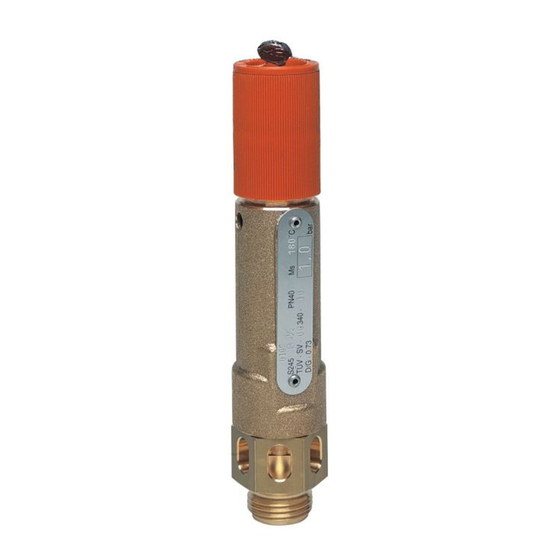
Sicherheitsventil
Safety valve
Soupape de sûreté
Veiligheidsklep
Valvola di sicurezza
D
Wird die Anlage für längere Zeit
außer Betrieb genommen, dann
sollte das Gerät in den An-
lüftzustand gebracht werden. Dazu
Stellgriff um 2 Umdrehungen gegen
den Uhrzeigersinn drehen.
2. Technische Daten
Betriebstemperatur
• max. 260 °C TÜV/CE
• max. 180 °C ASME
• min. -30 °C
Bauteilprüfzeichen
TÜV . SV . 10 . 340 . D
. D/G . 0,73 . p
o
p = Ansprechdruck
D
= Düsendurchmesser
o
ASME 30,492
Zertifiziert nach
Druckgeräterichtlinie 97/23/EG
Kennummer CE 0035
α
Ausflussziffer
TÜV
= 0,73
w
ASME
Kd = 0,863
Anschlussgrößen
G
1
/
" bis G 2"
2
Nicht geeignet für Wasserdampf.
3. Instandhaltung
Sicherstellen, dass sich kein Schmutz
um den Austrittsbereich des Sicherheits-
ventiles aufbaut.
4. Funktionsprüfungen
Die Intervalle für Funktionsprüfungen des
Sicherheitsventils sind unter Berücksich-
tigung der örtlichen Vorschriften für Druck-
behälter durch den Betreiber der Anlage
festzulegen (mindestens einmal jährlich
nach Empfehlung des Herstellers). Der
Betreiber der Anlage veranlasst, dass diese
Funktionsprüfungen regelmäßig durch
Fachpersonal vorgenommen werden.
50 mm
②
④
1. Installation
1.1.Installation requirement (fig. ①)
• Safety valves for pressurised air
should ideally be positioned vertically,
facing upwards in the pipeline or on
a pressure vessel. Other installation
positions on request.
• Install the safety valve in such a way
that during venting no harm can
occur to persons or objects adjacent
to the unit.
Under some circumstances it is
possible that high volumes can
discharge.
• Minimum clearances must be
adhered to (see figure ①)
• There must not be any shut-off devices
in the feeding pipe. The cross section
of the feeding pipe may not be smaller
than the entrance cross section of the
safety valve. The pressure drop in the
feeding pipe must not exceed 3 % of
the pressure difference between open-
ing overpressure and superimposed
back pressure during the greatest
mass flow which is to be carried off.
1.2 Assembly (fig. ② - ④)
• Visually inspect the cap, thread and
plug for damage
- a damaged valve must not be fitted.
• Seal the valve with hemp, sealing
tape or a copper gasket.
• Screw the valve in tight using a
suitable wrench and avoid damaging
the valve.
1.3 Commissioning (fig. ⑤)
• Turn the adjusting knob clockwise
until it tightens.
• The valve is now ready for service.
100 mm
③
⑤
GB
If the installation is taken out of service
for a long period, then the unit should
be turned to the venting position.
This is acheived by turning the
adjusting knob 2 turns anticlockwise.
2. Technical Data
Working temperature
• max. 260 °C TÜV/CE
• max. 180 °C ASME
• min. -30 °C
TÜV approval number
TÜV . SV . 10 . 340 . D
. D/G . 0,73 . p
o
p = set pressure
D
= nozzle diameter
0
ASME 30,492
Certified to
Pressure Equipment Directive 97/23/EC
Reference No. CE 0035
α
Discharge rate
TÜV
= 0.73
w
ASME
Kd = 0,863
Connection sizes
G
1
/
" to G 2"
2
Not suitable for steam
3. Field maintenance
Ensure dirt does not build up around the
discharge area of the safety valve.
4. Function tests
The intervals for function checks of the
safety valves must be fixed by the
operator of the installation under
consideration of the local requirements
for pressure tanks (at least once a year
according to the recommendation of the
manufacturer). The facility operator
should ensure that the function tests are
carried out regularly by an authorized
person.
①
Werbung

Verwandte Anleitungen für Honeywell S245B


Inhaltszusammenfassung für Honeywell S245B
- Seite 1 ① 50 mm S245B Einbau-Anleitung Installation Instructions • Instructions de montage Installatievoorschrift • 100 mm Istruzioni per il montaggio 0035 ② ③ Sicherheitsventil ④ ⑤ Safety valve Soupape de sûreté Veiligheidsklep Valvola di sicurezza 1. Einbau 1. Installation 1.1 Einbaubedingungen (Abb. ①) 1.1.Installation requirement (fig.
- Seite 2 Manufactured for and on behalf of the Environmental and Automation and Control Products wijzers van de klok vastdraaien Honeywell GmbH Combustion Controls Division of Honeywell Technologies Sàrl, fabrikant). • De klep is nu bedrijfsklaar Z.A. La Pièce16, 1180 Rolle, Switzerland by its Authorised...