Herunterladen Inhalt Inhalt Diese Seite drucken
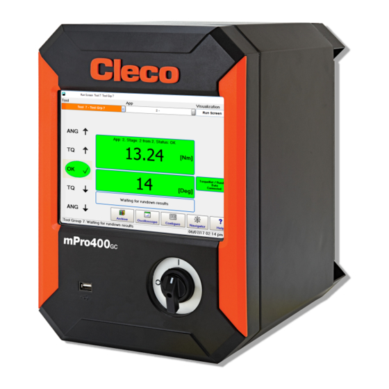
Cleco mPro400GCD-P Bedienungsanleitung
Vorschau ausblenden Andere Handbücher für mPro400GCD-P:

Werbung

Verfügbare Sprachen

Verfügbare Sprachen

Hardware Description
P2300HW-INT
2018-03
mPro400GCD-P
Global Controller Primary
For additional product information visit our website at www.ClecoTools.com

Werbung

Inhaltsverzeichnis
loading

Inhaltszusammenfassung für Cleco mPro400GCD-P

  • Seite 1 Hardware Description P2300HW-INT 2018-03 mPro400GCD-P Global Controller Primary For additional product information visit our website at www.ClecoTools.com...
  • Seite 2 Apex Tool Group. Disclaimer Apex Tool Group reserves the right to modify, supplement, or improve this document or the product without prior notice. Trademark Cleco is a registered trademark of Apex Brands, Inc. Apex Tool Group GmbH Industriestraße 1 73463 Westhausen Germany...
  • Seite 3: Inhaltsverzeichnis

    Contents Zu dieser Hardware-Beschreibung Sicherheit Produktbeschreibung Technische Daten Steckerbelegung Speicherzugänge Lieferumfang Notes on this Hardware-Description Safety Product Description Technical specifications Pin assignment Storage access Items delivered Acerca de esta descripción del hardware Seguridad Descripción del producto Datos técnicos Asignación de enchufes Acceso a memoria Volumen de suministro System...
  • Seite 5: Zu Dieser Hardware-Beschreibung

    Computer und Steuerung Anlage, an der dieses Produkt zum Einsatz kommt, zur Verfügung. Weiterführende Dokumente finden Sie Bestimmungsgemäße Verwendung Das Produkt ist Teil des Cleco Production Tools P1730E Verfahrensbeschreibung Schraubsystems und ist ausschließlich für den industriellen Schraubdiagramme Einsatz in Schraubprozessen bestimmt. Steuerung unter...
  • Seite 6: Ausbildung Des Personals

    P2300HW 2018-03 Ausbildung des Personals Dieses Zeichen bezeichnet eine möglicher- weise schädliche Situation. ACHTUNG! Das Schraubsystem darf nur von qualifizierten und ausge- Wird dieser Hinweis nicht beachtet kann bildeten Personen in Betrieb genommen, eingestellt und das Produkt oder Teile davon beschädigt geprüft werden.
  • Seite 7: Bei Der Installation

    P2300HW 2018-03 Systemrelevante Bei 115 VAC Kabel mit einem größeren Querschnitt  verwenden: Bestell-Nr. 541683-01. Sicherheitshinweise Vor der Inbetriebnahme Diese Sicherheitshinweise erheben keinen Anspruch auf Vollständigkeit. Bei der Installation sind nationale, staatli- Nur an geerdetem Netz (TN-Netz) betreiben. Der  che und örtliche Sicherheits- und Anschlussnormen obliga- Betrieb an IT-Netz ist unzulässig.
  • Seite 8: Beim Betrieb

    P2300HW 2018-03 Beim Betrieb Bei der Reparatur Steuerung bei ungewöhnlichen Geräuschen, unge- Reparaturen am Gerät sind unzulässig.   wöhnlicher Erhitzung und Vibrationen sofort abschal- ten. Netzstecker ziehen und das Schraubsystem von Bei der Entsorgung qualifiziertem Personal überprüfen und bei Bedarf Bestandteile des Schraubsystems bergen Risiken für reparieren lassen.
  • Seite 9: Produktbeschreibung

    P2300HW 2018-03 Produktbeschreibung Normative Verweise Produktrelevante EG-Richtlinien sowie eingehaltene Nor- men siehe EG-Konformitätserklärung. Steuerung für den Einsatz bei sicherheitskritischer Ver- schraubungen. Zertifikate Die Schraubersteuerung wird als Steuerungs- und Über- wachungseinheit für ein oder mehrere Werkzeuge an Ausstellende Stelle TÜV SÜD AG einem Arbeitsplatz eingesetzt.
  • Seite 10: Steckerbelegung

    P2300HW 2018-03 Steckerbelegung Alle Anschlüsse sind kurzschlussfest Integrierter Busabschluss. Kein externer Abschluss not- wendig. X5, X6 – Zusatzgeräte Pin Signal 8 pol. M12 Rundsteckverbinder • Alle Ausgänge liefern RS232 konforme Signale. A-codiert • Die Eingänge erlauben Spannungen im Bereich von - N.C.
  • Seite 11 P2300HW 2018-03 X9, X10 – Eingang/Ausgang An diesen Ein- / Ausgangssteckverbindern sind die notwendigen Signalverschaltungen aufgelegt. Die Ver- sorgungen der Signalgruppen sind nicht galvanisch verbunden, es wird getrenntes Auflegen verlangt. • 16 digitale Ein- und Ausgänge, opto-isoliert für 24V-Pegel / 0,5 A •...
  • Seite 12 P2300HW 2018-03 Signal X9 Signal X10 Bezeichnung Bezeichnung GND2 GND2 GND gemeinsam GND gemeinsam Ausgang O3 Ausgang O7 Ausgang O2 Ausgang O6 Ausgang O1 Ausgang O5 Ausgang O0 (Takten OK) z.B. Ausgang O4 Eingang I3 (Werkzeug Start) z.B. Eingang I7 Eingang I2 Eingang I6 Eingang I1...
  • Seite 13: Speicherzugänge

    Nur bei ausgeschalter Versorgungsspannung die CF-Karte ziehen oder stecken. Schwere Systemfehler  ACHTUNG! und Datenverlust sind bei Nichtbeachtung die Folge. Lieferumfang Lieferung auf Transportschäden und auf Übereinstimmung mit dem Lieferumfang überprüfen: • Globale Schraubersteuerung mPro400GCD-P • EG-Konformitätserklärung • Diese Hardware-Beschreibung • Garantie...
  • Seite 14 P2300HW 2018-03...
  • Seite 15: Notes On This Hardware-Description

    P3268C EC Declaration of Conformity Intended use Symbols in the text The product is a part of the Cleco Production Tools tighten- Italic Denotes menu options, e.g.,Diagnostics ing system and is intended exclusively for industrial use in > Denotes the selection of a menu option from fastening processes.
  • Seite 16: Operator Training

    P2300HW 2018-03 Operator training This sign warns of a possibly damaging sit- uation. ATTENTION! The tightening system may only be put into operation, Failure to observe this note may cause the adjusted and tested by qualified and trained personnel. product or parts thereof to be damaged. The personnel must be instructed by qualified employees of Apex Tool Group.
  • Seite 17: Prior To Initial Operation

    P2300HW 2018-03 System-relevant safety Prior to initial operation instructions Only operate on a grounded power supply (TN system).  Operation on the IT system is not permitted. We do not claim that these safety instructions are com- Ensure a standard-compliant PE connection. ...
  • Seite 18 P2300HW 2018-03 At the repair During remote-start operation (multiple tool setup) an inter- Send the complete nutrunner controller for repair to  ruption of TSNet bus leads to a delayed stop of the spindle/ your Sales & Service Center. tool. This delay is 2 seconds.Danger due to unexpected start of the motor or due to an expected but missing stop.
  • Seite 19: Product Description

    P2300HW 2018-03 Product Description Normative References Product-relevant EC directives and the standards complied Each controller is mainly used as a control and monitoring with, see EC Declaration of Conformity. unit for one or more tools at a workstation. Depending on the peripheral devices that are procured, the controller can Certifikates also be installed outside of the work environment.
  • Seite 20: Pin Assignment

    P2300HW 2018-03 Pin assignment X22 – ARCNET system bus All connections are short-circuit proof. The station controller has an integrated bus termination; X5, X6 – Serial port for additional devices therefore, no external termination is necessary. • All outputs provide RS232 conforming signals. Signal 8 pin M12 circular connector •...
  • Seite 21 P2300HW 2018-03 The required signal circuits are connected to these input/output connectors. The signal groups are not gal- vanically connected to the power supply; galvanic isolation is required. • 16 digital inputs/outputs, optically isolated for 24 V level/0.5 A • 8 inputs/8 outputs/2 +24 VDC/2 GND •...
  • Seite 22 P2300HW 2018-03 Signal X9 Signal X10 Name Name GND2 GND2 Common GND Common GND Output Output Output Output Output Output Output O0 (linking OK), e.g. Output Input I3 (tool start), e.g. Input Input Input Input Input Input Input Output O0-O3 common Output O4-O7 common +24 V2 +24 V2...
  • Seite 23: Storage Access

    Only pull out or plug in the CF card when the supply voltage is switched off. Otherwise, serious system  TION! errors and data loss will result. Items delivered Check delivery for transit damage and ensure that all items have been supplied: • Global Nutrunner Controller mPro400GCD-P • EC Declaration of Conformity • Hardware description • SP-1500 •...
  • Seite 24 P2300HW 2018-03...
  • Seite 25: Acerca De Esta Descripción Del Hardware

    Símbolos en el texto Este producto forma parte del sistema de apriete Cur- Identifica opciones de menú, p. ej. Diagnóstico Cleco Production Tools y está exclusivamente destinado siva para la aplicación industrial en procesos de atornillado. Uti- > Identifica la selección de una opción del menú en lice el controlador de apriete en las siguientes condiciones: un menú, p.
  • Seite 26: Formación Del Personal

    P2300HW 2018-03 Formación del personal ¡PRECAU- Un símbolo junto con la palabra PRECAU- CIÓN! CIÓN describe un peligro con un nivel de La puesta en servicio, los ajustes y la comprobación de riesgo bajo que, de no evitarse, puede este sistema de apriete deben ser realizados exclusiva- causar lesiones leves o moderadas, o mente por personas calificadas y capacitadas.
  • Seite 27: Antes De La Puesta En Servicio

    P2300HW 2018-03 Indicaciones de seguridad Utilice el cable de alimentación adjunto. En caso de  cambio, utilice un cable de alimentación normalizado. relevantes para el sistema En los cables de 115 VCA con una sección transversal  más grande, utilice: n.º de pedido 541683-01. Estas instrucciones de seguridad no pretenden ser exhaustivas.
  • Seite 28 P2300HW 2018-03 alcohol o medicamentos. Un momento de descuido Separe los distintos componentes del embalaje y elimí-  durante el trabajo con la herramienta puede provocar nelos según corresponda a cada tipo. lesiones graves. Entregue la herramienta y el controlador de apriete ...
  • Seite 29: Descripción Del Producto

    P2300HW 2018-03 Descripción del En caso de funcionamiento fuera de los límites de tensión permitidos, la fuente de alimentación integrada cambia a un modo de protección y producto se desconecta. Este modo de protección puede restablecerse reini- ciando el controlador de apriete. Referencias normativas El controlador de apriete se utiliza como unidad de control Para conocer las directivas CE relevantes, así...
  • Seite 30: Asignación De Enchufes

    P2300HW 2018-03 Asignación de enchufes Todas las conexiones son a prueba de cor- Terminación de bus integrada. No se necesita ninguna tocircuitos conexión externa. X5, X6 – Dispositivos adicionales Pin Señal Conexión de enchufe redondo de 8 pol. • Todas las salidas suministran señales conforme Codificación A RS232.
  • Seite 31 P2300HW 2018-03 X9, X10 – Entrada/salida Estas conexiones de enchufe de entrada/salida tienen asignadas las interconexiones de señal necesarias. Las alimentaciones de los grupos de señal no están conectadas galvánicamente, se requiere su colocación por separado. • 16 entradas y salidas digitales, optoaisladas para un nivel de 24 V/0.5 A •...
  • Seite 32 P2300HW 2018-03 Señal X9 Señal X10 Designación Designación Apagada Tierra2 Apagada Tierra2 CON. Junto con tierra CON. Junto con tierra Salida Salida Salida Salida Salida Salida Salida S0 (Secuenciado OK) p. ej. Salida Entrada E3 (arranque herramienta) Entrada p. ej. Entrada Entrada Entrada...
  • Seite 33: Acceso A Memoria

    Volumen de suministro Compruebe que la mercancía entregada no presente daños de transporte y que coincida con el volumen de suministro esperado: • Controlador de apriete global mPro400GCD-P • Declaración de conformidad CE • Esta descripción del hardware •...
  • Seite 34: System

    P2349HW-INT 2018-08 System CF-card mPro400GCD-P Main switch Pos. Product Possible connections Serie 30E×N…/50E×N… 1× Serie 18E×E…/48E×E… 1× Serie 17BP…/47BA… 15× Serie 18E×E…/48E×E… + mPro400GC-S 15× Serie 30E×N…/50E×N…+ mPro400GCD-S 15× Access Point ArcNet-Kabel TSNet-Kabel...
  • Seite 35: Connections

    P2349HW-INT 2018-08 Connections Abb. 9-1: Connection positions Designation Designation Ethernet RJ45 10/100 BASE-T Connector #1 I/O Connector Ethernet RJ45 10/100 BASE-T Connector #2 I/O Connector USB V2.0 Port #1 System Bus Connector TSnet USB V2.0 Port #2 System Bus Connector ArcNet Serial RS232-1 Connector #1 Power supply connection Serial RS232-2 Connector #2...
  • Seite 36: Dimensions

    P2349HW-INT 2018-08 Dimensions mPro400GCD-P 327,66 mm (12,900" ) 276,23 mm 266,7 mm (10.875" ) (10,500" ) 381,0 mm (15.000" ) 288,04 mm (11.340") 336,30 mm (13.240" )
  • Seite 38 POWER TOOLS SALES & SERVICE CENTERS Please note that all locations may not service all products. Contact the nearest Cleco ® Sales & Service Center for the appropriate facility to handle your service requirements. Sales Center Service Center NORTH AMERICA | SOUTH AMERICA...

Inhaltsverzeichnis